NetComm IFWA-661 User manual

Installation Guide
IFWA-661 - Outdoor Wireless Antenna

IFWA-661 Outdoor Wireless Antenna –Installation Guide
2 of 63
v1.0 September 20, 2019
© NetComm Wireless 2019
Important Notice
This device, like any wireless device, operates using radio signals which cannot guarantee the transmission and
reception of data in all conditions. While the delay or loss of signal is rare, you should not rely solely on any
wireless device for emergency communications or otherwise use the device in situations where the interruption of
data connectivity could lead to death, personal injury, property damage, data loss, or other loss. NetComm
Wireless accepts no responsibility for any loss or damage resulting from errors or delays in transmission or
reception, or the failure of the NetComm Wireless IFWA-661 Outdoor Wireless Antenna to transmit or receive such
data.
Safety and Hazards
Warning –Do not connect or disconnect cables or devices to or from the SIM card tray or Ethernet port in hazardous locations such as
those in which flammable gases or vapours may be present, but normally are confined within closed systems; are prevented from
accumulating by adequate ventilation; or the location is adjacent to a location from which ignitable concentrations might occasionally be
communicated.
Copyright
Copyright© 2019 NetComm Wireless Limited. All rights reserved.
NetComm Wireless Limited was acquired by Casa Systems, Inc. a Delaware company on 1 July 2019. The
information contained herein is proprietary to Casa Systems, Inc. No part of this document may be translated,
transcribed, reproduced, in any form, or by any means without prior written consent of Casa Systems, Inc.
Trademarks and registered trademarks are the property of NetComm Wireless Limited or their respective owners.
Specifications are subject to change without notice. Images shown may vary slightly from the actual product.
Note –This document is subject to change without notice.

IFWA-661 Outdoor Wireless Antenna –Installation Guide
3 of 63
v1.0 September 20, 2019
© NetComm Wireless 2019
Document history
This document covers the following product:
NetComm Wireless IFWA-661 Outdoor Wireless Antenna
V E R .
D O C U M E N T D E S C R I P T I O N
D A T E
v1.0
Initial document release
September 20, 2019
Table i. - Document revision history

IFWA-661 Outdoor Wireless Antenna –Installation Guide
4 of 63
v1.0 September 20, 2019
© NetComm Wireless 2019
Contents
Overview .............................................................................................................................................................................. 6
Introduction.............................................................................................................................................................................................................. 6
Target audience....................................................................................................................................................................................................... 6
Prerequisites............................................................................................................................................................................................................. 6
Product introduction ............................................................................................................................................................. 7
Physical dimensions and interfaces ....................................................................................................................................... 8
Physical dimensions................................................................................................................................................................................................. 8
Interfaces .................................................................................................................................................................................................................. 9
Installation considerations................................................................................................................................................... 10
Installing the Outdoor Wireless Antenna............................................................................................................................. 11
Determining the best location for the Outdoor Wireless Antenna.................................................................................................................... 11
Assemble and attach the mounting bracket........................................................................................................................................................ 12
Connect the Smart Antenna Tool to the Outdoor Wireless Antenna................................................................................................................ 14
Perform the site survey .......................................................................................................................................................................................... 15
Install mount on roof top....................................................................................................................................................................................... 16
Place the Outdoor Wireless Antenna on the pole .............................................................................................................................................. 17
Assemble the Outdoor Wireless Antenna Power supply weather seal.............................................................................................................. 18
Aligning the Outdoor Wireless Antenna ............................................................................................................................. 23
Process flow (subject to change) .......................................................................................................................................................................... 23
Installation flow –Site survey ................................................................................................................................................................................ 36
Installation flow - Post site survey ......................................................................................................................................................................... 36
Connecting the Outdoor Wireless Antenna ........................................................................................................................ 49
Grounding and power surges ............................................................................................................................................................................... 49
Powering the Outdoor Wireless Antenna............................................................................................................................................................ 50
Acronyms............................................................................................................................................................................ 51
Appendix............................................................................................................................................................................ 52
Inserting a SIM card............................................................................................................................................................................................... 52
Using the Smart Antenna Tool.............................................................................................................................................................................. 54
Quick Copy Items .................................................................................................................................................................................................. 58
Safety and product care...................................................................................................................................................... 59
RF Exposure ........................................................................................................................................................................................................... 59
FCC Statement....................................................................................................................................................................................................... 59
Electrical safety ...................................................................................................................................................................................................... 60
Connection to a car ............................................................................................................................................................................................... 60
Distraction .............................................................................................................................................................................................................. 60
Product handling ................................................................................................................................................................................................... 60
Faulty and damaged products.............................................................................................................................................................................. 61
Interference ............................................................................................................................................................................................................ 61
Explosive environments......................................................................................................................................................................................... 62

IFWA-661 Outdoor Wireless Antenna –Installation Guide
6 of 63
v1.0 September 20, 2019
© NetComm Wireless 2019
Overview
Introduction
This document provides you with an overview of the installation process for the IFWA-661 Outdoor Wireless
Antenna.
Target audience
This document is intended for system integrators or experienced hardware installers who understand
telecommunications terminology and concepts.
Prerequisites
Before continuing with the installation of your IFWA-661 router, please confirm that you have:
An electronic computing device with a working wireless network adapter and a web browser such as Internet
Explorer®, Mozilla Firefox® or Google Chrome™.
Read the entire Safety and product care section of this document and RF Exposure information.
Notation
The following symbols may be used in this document:
Note –This note contains useful information.
Important –This is important information that may require your attention.
Warning –This is a warning that may require immediate action in order to avoid damage or injury.

IFWA-661 Outdoor Wireless Antenna –Installation Guide
7 of 63
v1.0 September 20, 2019
© NetComm Wireless 2019
Product introduction
Product overview
Rural and regional homes and businesses, remote commercial sites and metropolitan fringe districts located
beyond the reach of fixed line infrastructure rely on mobile networks to access broadband Internet.
Designed to optimise signal strength in weak signal areas, the Outdoor Wireless Antenna (OWA) is positioned on
the exterior of the premises to overcome distance limitations and geographical obstructions and deliver high-
speed LTE broadband connectivity to wired and wireless clients in the property via an indoor router.
Package contents
The NetComm Wireless IFWA-661 in-box contents include:
1 x NetComm Wireless IFWA-661 Outdoor Wireless Antenna (also referred to as the IFWA, OWA and OA).
1 x Assembled mount bracket and hardware compatible with all DIRECTV 2” mounts
Accessories used in this solution (packaged separately):
1 x Antenna Power Supply (POE-03) –used to power the OWA during normal operation
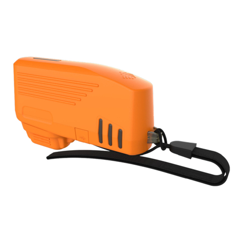
1 x Smart Antenna Tool –used to power and provide a wireless interface to the OWA during installation
If any of these items are missing or damaged, please contact NetComm Wireless Support immediately. The
NetComm Wireless Support website can be found at: http://support.netcommwireless.com.

IFWA-661 Outdoor Wireless Antenna –Installation Guide
8 of 63
v1.0 September 20, 2019
© NetComm Wireless 2019
Physical dimensions and interfaces
Physical dimensions
Below is a list of the physical dimensions of the IFWA-661.
Figure 1 –IFWA-661 Outdoor Wireless Antenna Dimensions
I F W A - 661 D I M E N S I O N S
Length
17.5” (445 mm)
Width
11.3” (287 mm)
Height
4.5” (113 mm)
Weight
~5.7lbs (~2.59 kg)
Table 1 - Device Dimensions

IFWA-661 Outdoor Wireless Antenna –Installation Guide
9 of 63
v1.0 September 20, 2019
© NetComm Wireless 2019
Interfaces
Figure 2 –Interfaces
I T E M
D E S C R I P T I O N
Antenna panel
Includes 2 x pairs Cross polarised antennas
and GPS antenna
Smart Antenna Tool port
Connect the Smart Antenna Tool here
SIM hatch
Open the hatch to insert SIM here
Antenna Power Supply port (PoE)
Provides power and data connectivity to the
Outdoor Wireless Antenna with Ethernet
cable
Table 2 –Interfaces
Antenna panel
Smart Antenna Tool
port
SIM hatch
Antenna Power
Supply port (PoE)

IFWA-661 Outdoor Wireless Antenna –Installation Guide
10 of 63
v1.0 September 20, 2019
© NetComm Wireless 2019
Installation considerations
As the Outdoor Wireless Antenna is aligned specifically for a property, please take note of the following when
installing the equipment:
After alignment, do not move, place anything in front of, or adjust the position of the Outdoor Wireless
Antenna since this will likely have a negative impact on the signal quality and performance of the wireless
service.
Keep trees and branches away from the Outdoor Wireless Antenna.
The equipment must be protected from running water, steam and excessive heat and must be installed
according to the guidelines in this document.
The Antenna Power Supply (POE-03) and Wi-Fi Gateway must be installed in a well-ventilated area and near
a dedicated power outlet which allows easy visibility of the indicator lights.
If an existing customer has carried out external construction work on the property, the antenna may need to
be re-aligned to ensure the installation is still operating at peak performance.
The Outdoor Wireless Antenna location is determined by radio frequency performance and it may not be
possible to relocate the antenna when moving to a new property. It is advised that a site survey be
conducted before initiating the installation process.

IFWA-661 Outdoor Wireless Antenna –Installation Guide
11 of 63
v1.0 September 20, 2019
© NetComm Wireless 2019
Installing the Outdoor Wireless Antenna
The image below illustrates a typical installation of the Outdoor Wireless Antenna.
Figure 3 - Typical Outdoor Wireless Antenna Installation
Determining the best location for the Outdoor Wireless
Antenna
Determining the best location for the Outdoor Wireless Antenna involves:
1Performing a survey of the site using the Smart Antenna Tool.
2Consulting the customer about mounting location, grounding and cable routing based on results of the RF
test, aesthetics and any planned renovations to the property.
When selecting a location to mount the Outdoor Wireless Antenna, ensure that:
lock of the desired cell and optimal signal level is achieved.
the mounting position is unobtrusive and aesthetically pleasing where possible.
the mount/antenna is not closer than three feet from other antenna equipment.
the customer has obtained HOA approval for installation if required. This is the sole responsibility of the
customer.
Where possible, avoid mounting the Outdoor Wireless Antenna so that it is aimed back over the roof of the
property.

IFWA-661 Outdoor Wireless Antenna –Installation Guide
12 of 63
v1.0 September 20, 2019
© NetComm Wireless 2019
Assemble and attach the mounting bracket
Notes on mounting:
Use a standard 13mm socket wrench for all bolts
Tighten bolts to the following torque settings:
Captive radome mount bolts: 35 in-lbs
Angle pivot bolt: 65 in-lbs
Pipe clamp bolt: 80 in-lbs
Do not over tighten bolts
Figure 4 - IFWA-661 mounting bracket and bolts
Radome
mount
Pipe clamp
Pipe clamp
bolt
Captive radome
mount bolt
Angle pivot
bolt

IFWA-661 Outdoor Wireless Antenna –Installation Guide
13 of 63
v1.0 September 20, 2019
© NetComm Wireless 2019
Mounting bracket assembly
1Attach the pipe clamp to the radome mount using the angle pivot bolt, nut and washer.
Figure 5 - Mounting bracket assembly
2Attach the assembled mounting bracket to the antenna as shown below. Tighten the captive radome mount
bolts to the torque settings described here.
Figure 6 - Attaching the mounting bracket to the Outdoor Wireless Antenna
Pipe clamp
Angle pivot bolt
Pipe clamp
bolt
Captive radome
mount bolt
Radome mount
Angle pivot
bolt nut
Angle pivot
bolt washer

IFWA-661 Outdoor Wireless Antenna –Installation Guide
14 of 63
v1.0 September 20, 2019
© NetComm Wireless 2019
Connect the Smart Antenna Tool to the Outdoor
Wireless Antenna
1Turn the plug on the console port hatch counter-clockwise so that it is in the unlocked (vertical) position as
shown in the image below.
Figure 7 - Unlocking the console port hatch
2Pull the plug out to reveal the console port.
Figure 8 - Console port

IFWA-661 Outdoor Wireless Antenna –Installation Guide
15 of 63
v1.0 September 20, 2019
© NetComm Wireless 2019
3Remove the cap from the head of the Smart Antenna Tool and insert it into the console port as shown in the
picture below.
Figure 9 - Attached Smart Antenna Tool
Perform the site survey
Push the power button on the Smart Antenna Tool to turn it on. After a few seconds, the LEDs illuminate. On each
start up, the Smart Antenna Tool LEDs flash both red and green twice a second, indicating that the compass
requires calibrating. To calibrate the device, first isolate it from any magnetic field or metal structures (for example,
vehicles, the antenna pole, power lines, etc) and then rotate the unit fully through all three axes. See the diagrams
below.
The LEDs stop flashing when calibration has been performed successfully.

IFWA-661 Outdoor Wireless Antenna –Installation Guide
16 of 63
v1.0 September 20, 2019
© NetComm Wireless 2019
When the Smart Antenna Tool is connected to the OWA, it enters Cell scanning mode.
During cell scanning mode, the LED indicators display as below, depending on the status.
Figure 10 - Smart Antenna Tool LED statuses in cell scanning mode
Connect your wireless device (e.g. laptop/tablet/smartphone) to the SSID of the alignment tool. In a web browser,
go to http://192.168.3.1and use the alignment tool to estimate the best position for the Outdoor Wireless Antenna
while you are on the ground. If the web user interface is not displayed, use http://192.168.3.1/data_entry.html
Install mount on roof top
When you have found the best spot to install the Outdoor Wireless Antenna, install the mount on the roof using
appropriate materials.

IFWA-661 Outdoor Wireless Antenna –Installation Guide
17 of 63
v1.0 September 20, 2019
© NetComm Wireless 2019
Place the Outdoor Wireless Antenna on the pole
1Assemble the Pipe Bracket to pole, pointing bracket in desired antenna direction. Secure the pipe clamp
bolts
Figure 11 - Assembling pipe bracket to pole
2Alternately tighten the top and bottom pipe clamp bolts to maintain even pressure on the pipe, to 80 in-lb.
Figure 12 - Tightening pipe clamp bolts

IFWA-661 Outdoor Wireless Antenna –Installation Guide
18 of 63
v1.0 September 20, 2019
© NetComm Wireless 2019
Assemble the Outdoor Wireless Antenna Power supply
weather seal
The Outdoor Wireless Antenna Power supply weather seal must be properly attached to prevent dust and water
from entering the Outdoor Wireless Antenna’s housing.
To connect Ethernet cable via the Power supply weather seal:
1Unscrew the weather cap and remove the rubber gasket.
2Separate the rubber seal and the ferrule.
Figure 13 - Rubber seal and ferrule
3Twist the neck for the seal counter-clockwise to remove it from the Outdoor Wireless Antenna. You should
now have 5 pieces of the weather seal.
Figure 14 - Weather seal in five parts
4Place the Ethernet cable through the nut first, as shown below.
Figure 15 - Nut placed over Ethernet cable

IFWA-661 Outdoor Wireless Antenna –Installation Guide
19 of 63
v1.0 September 20, 2019
© NetComm Wireless 2019
5Place the ferrule over the Ethernet cable as shown, making sure that the “teeth” are facing the nut.
Figure 16 - Ferrule placed over Ethernet cable
6Place the rubber seal over the Ethernet cable with the wide end toward the RJ45 plug. See the image below
for the correct orientation.
Figure 17 - Rubber seal placed over Ethernet cable
7Push the ferrule over the rubber seal to prevent it from coming apart.
Figure 18 - Ferrule placed over rubber seal

IFWA-661 Outdoor Wireless Antenna –Installation Guide
20 of 63
v1.0 September 20, 2019
© NetComm Wireless 2019
8Place the washer seal over the Ethernet cable as shown below. Ensure that the inside protruding lip is on the
opposite side of the Ethernet plug.
Figure 19 - Washer seal placed over Ethernet cable
9Place the neck over the Ethernet cable as shown below.
Figure 20 - Neck placed over Ethernet cable
Table of contents
Other NetComm Antenna manuals