netsys NV-520G User manual

N
N
NV
V
V-
-
-5
5
52
2
20
0
0G
G
G
I
I
In
n
nd
d
du
u
us
s
st
t
tr
r
ri
i
ia
a
al
l
l
4
4
4
G
G
Gi
i
ig
g
ga
a
a
L
L
LA
A
AN
N
N
O
O
Ov
v
ve
e
er
r
r
V
V
VD
D
DS
S
SL
L
L2
2
2
E
E
Ex
x
xt
t
te
e
en
n
nd
d
de
e
er
r
r
w
w
wi
i
it
t
th
h
h
D
D
DI
I
I
S
S
Sw
w
wi
i
it
t
tc
c
ch
h
h
U
U
US
S
SE
E
ER
R
R’
’
’S
S
S
M
M
MA
A
AN
N
NU
U
UA
A
AL
L
L

NV-520G Industrial grade LAN Extender USER’S MANUAL Rev. A.
1
Copyright
Copyright © 2023 by National Enhance Technology Corp. All rights reserved.
Trademarks
NETSYS is a trademar of National Enhance Technology Corp.
Other brand and product names are registered trademar s or trademar s of their respective holders.
Legal Disclaimer
The information given in this document shall in no event be regarded as a guarantee of conditions or characteristics. With respect
to any examples or hints given herein, any typical values stated herein and/or any information regarding the application of the
device, National Enhance Technology Corp. hereby disclaims any and all warranties and liabilities of any ind, including without
limitation warranties of non-infringement of intellectual property rights of any third party.
Statement of Conditions
In the interest of improving internal design, operational function, and/or reliability, NETSYS reserves the right to ma e changes to
the products described in this document without notice. NETSYS does not assume any liability that may occur due to the use or
application of the product(s) or circuit layout(s) described herein.
Maximum signal rate derived from IEEE Standard specifications. Actual data throughput will vary. Networ conditions and
environmental factors, including volume of networ traffic, building materials and construction, and networ overhead, lower actual
data throughput rate. Netsys does not warrant that the hardware will wor properly in all environments and applications, and ma es
no warranty and representation, either implied or expressed, with respect to the quality, performance, merchantability, or fitness for
a particular purpose. Ma e sure you follow in line with the environmental conditions to use this product.

NV-520G Industrial grade LAN Extender USER’S MANUAL Rev. A.
2
Foreword: Ethernet extender for industrial-grade solution
Attention:
Be sure to read this manual carefully before using this product. Especially Legal Disclaimer, Statement
of Conditions and Safety Warnings.
Netsys' NV-520G is a VDSL2 line port over 4 x Giga Ethernet ports that provide an economical solution for your industrial
applications. Compliant with ITU-T G.993.2 VDSL2 standard, the NV-520G supports a maximum bandwidth of up to 160Mbps
symmetric in VDSL2 Profile (35b) solution. The NV-520G also supports both CO (Master) and CPE (Slave) modes selectable
through DIP Switch.
NV-520G support DIN-Rail and Industrial-grade design compliant with quic , easy, economical, and high-performance
broadband/multimedia services to industrial environments such as IP surveillance、Factory auto control、 MRT、 Train station、
Weather station、 Military training system、Tic et vending machine、Par ing system、 Monitoring system、 Farm、Ship、Jail etc.
point to point applications.
Caution:
The NV-520G is industrial-grade applications. This product does not have waterproof protection.

NV-520G Industrial grade LAN Extender USER’S MANUAL Rev. A.
3
Safety Warnings
For your safety, be sure to read and follow all warning notices and instructions before using the device.
DO NOT open the device or unit. Opening or removing the cover may expose you to dangerous high voltage points or other
ris s. ONLY qualified service personnel can service the device. Please contact your vendor for further information.
Use ONLY the dedicated power supply for your device. Connect the power to the right supply voltage (110V AC used for
North America and 230V AC used for Europe. NV-520G supports 15 to 48 VDC dual power input (Redundant power)).
lace connecting cables carefully so that no one will step on them or stumble over them. DO NOT allow anything to rest on
the power cord and do NOT locate the product where anyone can wor on the power cord.
DO NOT install nor use your device during a thunderstorm. There may be a remote ris of electric shoc from lightning.
DO NOT expose your device to dampness, dust or corrosive liquids.
DO NOT use this product near water, for example, in a wet basement or near a swimming pool.
Connect ONLY suitable accessories to the device.
Make sure to connect the cables to the correct ports.
DO NOT obstruct the device ventilation slots, as insufficient air flow may harm your device.
DO NOT place items on the device.
DO NOT use the device for outdoor applications directly, and ma e sure all the connections are indoors or have waterproof
protection place.
Be careful when unplugging the power, because it may produce spar s.
Keep the device and all its parts and accessories out of the reach of children.
Clean the device using a soft and dry cloth rather than liquid or atomizers. Power off the equipment before cleaning it.
This product is recyclable. Dispose of it properly.

NV-520G Industrial grade LAN Extender USER’S MANUAL Rev. A.
4
TABLE OF CONTENTS
COPYRIGHT ........................................................................................................................................................ 1
FOREWORD: VDSL2 FOR INDUSTRIAL-GRADE SOLUTION ............................................................................ 2
SAFETY WARNINGS ........................................................................................................................................... 3
CHAPTER 1. UNPACKING INFORMATION ......................................................................................................... 6
1.1 Chec List ...................................................................................................................................................................................... 6
CHAPTER 2. INSTALLING NV-520G .................................................................................................................... 7
2.1 Hardware Installation ...................................................................................................................................................................... 7
2.2 Pre-installation Requirements ........................................................................................................................................................ 7
2.3 General Rules ................................................................................................................................................................................ 8
2.4 Connecting NV-520G ..................................................................................................................................................................... 9
2.5 Terminal Bloc and DIN-Rail mount installation .............................................................................................................................. 9
2.6 Connecting the RJ-11 / RJ-45 Ports ............................................................................................................................................. 11

NV-520G Industrial grade LAN Extender USER’S MANUAL Rev. A.
5
2.7 Industrial NV-520G Application ..................................................................................................................................................... 13
CHAPTER 3. HARDWARE DESCRIPTION ........................................................................................................ 15
3.1 Front Panel ................................................................................................................................................................................... 16
3.2 Front Indicators ............................................................................................................................................................................ 21
3.3 Rear Panel ................................................................................................................................................................................... 22
3.4 Side Panel .................................................................................................................................................................................... 22
APPENDIX A: CABLE REQUIREMENTS ........................................................................................................... 27
APPENDIX B: PRODUCT SPECIFICATION ....................................................................................................... 29
APPENDIX C: TROUBLESHOOTING ................................................................................................................ 32
APPENDIX D: IP-30 PROTECTION OF METAL CASE ...................................................................................... 38
APPENDIX E: COMPLIANCE INFORMATION ................................................................................................... 40
WARRANTY ....................................................................................................................................................... 43
CHINESE SJ/T 11364-2014 ................................................................................................................................ 44

NV-520G Industrial grade LAN Extender USER’S MANUAL Rev. A.
6
CHA TER 1.
UN ACKING INFORMATION
1.1 Check List
Carefully unpac the pac age and chec its contents against the chec list.
ackage Contents:
1 x NV-520G device 1 x QR code for user’s
manual hyperlin .
Accessory Kit : 1 x DIN-Rail mounting plate, 2 x screws, 4 x
Rubber Feet, Protective caps (RJ-11*1, RJ-45*3), 1 x 6pin
Terminal Bloc , 1 x 2pin Terminal Bloc
Notes:
1. Please inform your dealer immediately for any missing or damaged parts. If possible, retain the carton including the
original pac ing materials. Use them to repac the unit in case there is a need to return for repair.
2. If the product has any issue, please contact your local distributor.
3. Please use the provided protective caps for unused ports.
4. Please loo for the QR code on the bottom of the product, the user can launch the QR code scanning program to
scan and download the user’s manual electronic format file. Above QR code icon is for reference.
5. Power Input: This model supports 15~48V DC power adapters with recommended 15 Watts or above.

NV-520G Industrial grade LAN Extender USER’S MANUAL Rev. A.
7
Chapter 2. Installing NV-520G
Caution:
lease equip the anti-static devices during INSTALLATION.
2.1 Hardware Installation
This chapter describes how to install NV-520G and establish the networ connections. NV-520G may be installed on
any level surface (eg. a table or shelf). However, please ta e note of the following minimum site requirements before
you begin.
2.2 re-installation Requirements
Before you start the actual hardware installation, ma e sure you can provide the right operating environment, including
power requirements, sufficient physical space, and proximity to other networ devices that are to be connected.
Verify the following installation requirements:
Power requirements: DC 15 to 48VDC redundant power.
The NV-520G should be located in a cool dry place, with at least 10cm/4in of space at the front and bac
for ventilation.

NV-520G Industrial grade LAN Extender USER’S MANUAL Rev. A.
8
Place NV-520G away from direct sunlight, heat sources, or areas with a high amount of electromagnetic
interference.
Chec if the networ cables and connectors needed for installation are available.
Do not install phone lines strapped together with AC power lines, or telephone office line with voice signal.
Avoid installing this device with radio amplifying stations nearby or transformer stations nearby.
2.3 General Rules
Before ma ing any connections to the NV-520G, please note the following rules:
Ethernet ort (RJ-45)
All networ connections to the NV-520G Ethernet ports must be made using Category 5 UTP/STP or above
for 100/1000 Mbps, Category 3, 4 UTP for 10Mbps.
No more than 100 meters of cabling may be used between MUX or Ethernet Switch and an end node.
Line ort (RJ-11)
All networ connections to the RJ-11port must use 24~26 gauge with twisted pair phone wiring.
We do not recommend the use of the telephone line 28 gauge or above.
The RJ-11 connectors have six positions, two of which are wired. The NV-520G uses the center two pins.
The pin out assignment for these connectors is presented below.
Please note that the line port is no polarity, therefore user can reverse the two wires of the phone cable
when installed.
NV-520G Industrial grade LAN Extender USER’S MANUAL Rev. A.
9
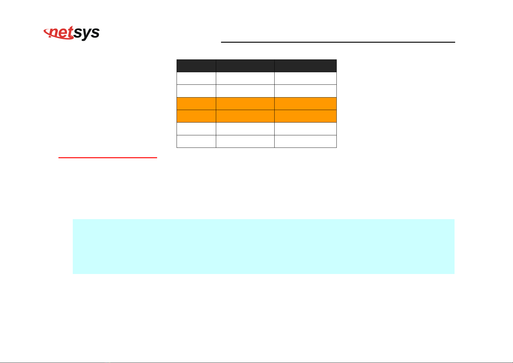
RJ-11 Pin out Assignments
in# MNEMONIC FUNCTION
1 NC Unused
2 NC Unused
3 DSL Used
4 DSL Used
5 NC Unused
6 NC Unused_
2.4 Connecting NV-520G
NV-520G has four Ethernet ports which support connection to Ethernet operation. The devices attached to these ports
must support auto-negotiation /10Base-T / 100Base-TX / 1000Base-TX unless they will always operate at half duplex.
Use any of the Ethernet ports to connect networ ing devices such as Monitor systems, Servers, Ethernet Switches.
Notes:
1. The (RJ11/Terminal Bloc ) Line port is used to connect the telephone that is connected to both NV-520G between
CO and CPE mode (Point-to-point solution).
2. Use the provided protective caps for unused ports to avoid dust intrusion.
3. The Slave device (CPE) must be connected to the Master device (CO) through the telephone wire. The Slave
cannot be connected to another Slave, and the Master cannot be connected to another Master.
Table of contents
Other netsys Extender manuals


