netsys NV-202M User manual

N
N
NV
V
V-
-
-2
2
20
0
02
2
2M
M
M/
/
/S
S
S
L
L
LA
A
AN
N
N
e
e
ex
x
xt
t
te
e
en
n
nd
d
de
e
er
r
r
w
w
wi
i
it
t
th
h
h
R
R
Re
e
em
m
mo
o
ot
t
te
e
e
P
P
Po
o
ow
w
we
e
er
r
r
U
U
Us
s
se
e
er
r
r’
’
’s
s
s
M
M
Ma
a
an
n
nu
u
ua
a
al
l
l

NV-202M/S LAN extender with Remote Power USER’S MANUAL Ver. A.2
1
Co yright
Copyright © 2017 by National Enhance Technology Corp. All rights reserved.
Trademarks
NETSYS is a trade ark of National Enhance Technology Corp.
Other brand and product na es are registered trade arks or trade arks of their respective holders.
Legal Disclaimer
The infor ation given in this docu ent shall in no event be regarded as a guarantee of conditions or characteristics. With respect
to any exa ples or hints given herein, any typical values stated herein and/or any infor ation regarding the application of the
device, National Enhance Technology Corp. hereby disclai s any and all warranties and liabilities of any kind, including without
li itation warranties of non-infringe ent of intellectual property rights of any third party.
Statement of Conditions
In the interest of i proving internal design, operational function, and/or reliability, NETSYS reserves the right to ake changes to
the products described in this docu ent without notice. NETSYS does not assu e any liability that ay occur due to the use or
application of the product(s) or circuit layout(s) described herein.
Maxi u signal rate derived for IEEE Standard specifications. Actual data throughput will vary. Network conditions and
environ ental factors, including volu e of network traffic, building aterials and construction, and network overhead lower actual
data throughput rate. Netsys does not warrant that the hardware will work properly in all environ ents and applications, and akes
no warranty and representation, either i plied or expressed, with respect to the quality, perfor ance, erchantability, or fitness for
a particular purpose. Make sure you follow in line with the environmental conditions to use this roduct.

NV-202M/S LAN extender with Remote Power USER’S MANUAL Ver. A.2
2
Foreword
NV-202M syste delivers power and IP connectivity at distances up to 2k (6,562ft) using existing or new copper twisted pair phone
cable. These innovative trans ission techniques result in power feeding and data over a single pair phone wire and are ideal
for deploying extended Ethernet where there are no or li ited electricity at one end. With auto atic fault protection and power
onitoring, these ensures reliable delivery of essential power and data / video to and fro re ote locations. Operators in diverse
enterprises will now be able to deploy PoE devices in any service location. Install network security ca eras, wireless access points,
security / RFID scanners or access control syste s in any place where you have basic wire connectivity.
The NV-202M / S provide extended-length power and Ethernet connections over one pair Cat. 5 or above twisted air phone cable.
The NV-202M / S works as Ethernet to / fro VDSL subscriber site conversion NV-202M/S.
The front-panel provides LED indicators of power syste and interface status. Full- or half-duplex ode of LAN operation is
auto atically sensed and configured. VDSL link rates are configured by NV-202M over the auto-speed . Therefore, NV-202M / S
supports auto-speed operations on the subscriber-site and power protections as OVP(Over Voltage Protection), OCP(Over Current
Protection), OTP(Over Te perature Protection), robust short-circuit protection and surge protection, as well as are part of an ideal
solution for delivering cost-effective, high-perfor ance broadband / ulti edia services to point to point application.
Attention:
Be sure to read this manual carefully before using this roduct. Es ecially Legal Disclaimer, Statement
of Conditions and Safty Warnings.
Caution:
The NV-202M/S is for indoor applications only. This product does not have waterproof protection. Do not use in harsh
environ ents (Over te perature range: 0°C ~ 50°C (32°F ~ 122°F)).

NV-202M/S LAN extender with Remote Power USER’S MANUAL Ver. A.2
3
Safety Warnings
For your safety, be sure to read and follow all warning notices and instructions before using the device.
DO NOT open the device or unit. Opening or re oving covers can expose you to dangerous high voltage points or other
risks. ONLY qualified service personnel can service the device. Please contact your vendor for further infor ation.
Use ONLY the dedicated power supply for your device. Connect the power cord or power adapter to the right supply voltage
(110V AC in North A erica or 230V AC in Europe).
DO NOT use the device if the power supply is da aged as it ight cause electrocution. If the power supply is da aged,
re ove it fro the power outlet. DO NOT atte pt to repair the power supply. Contact your local vendor to order a new
power supply.
Place connecting cables carefully so that no one will step on the or stu ble over the . DO NOT allow anything to rest on
the power cord and do not locate the product where anyone can work on the power cord.
DO NOT install nor use your device during a thunderstor . There ay be a re ote risk of electric shock fro lightning.
DO NOT expose your device to da pness, dust or corrosive liquids.
DO NOT use this product near water, for exa ple, in a wet base ent or near a swi ing pool.
Connect ONLY suitable accessories to the device. Make sure to connect the cables to the correct ports.
DO NOT obstruct the device ventilation slots, as insufficient airflow ay har your device.
DO NOT place ite s on the device.
DO NOT use the device for outdoor applications, and ake sure all the connections are indoors. There ay be a re ote
risk of electric shock fro lightning.
Be careful when unplugging the power, because the transfor er ay be very hot.
Kee the device and all its parts and accessories out of children’s reach.
Clean the device using a soft and dry cloth rather than liquid or ato izers. Power off the equip ent before cleansing it.
This product is recyclable. Dispose of it properly.

NV-202M/S LAN extender with Remote Power USER’S MANUAL Ver. A.2
4
TABLE OF CONTENTS
COPYRIGHT ........................................................................................................................................................ 1
SAFETY WARNINGS ........................................................................................................................................... 3
CHAPTER 1. UNPACKING INFORMATION ......................................................................................................... 6
1.1 Check List ......................................................................................................................................................................................6
CHAPTER 2. INSTALLING THE NV-202M/S ........................................................................................................ 7
2.1 Hardware Installation......................................................................................................................................................................7
2.2 Pre-installation Require ents ........................................................................................................................................................7
2.3 General Rules ................................................................................................................................................................................8
2.4 Connecting the NV-202M and NV-202S .........................................................................................................................................9
2.5 Connecting the Line / Ethernet Ports............................................................................................................................................10
CHAPTER 3. HARDWARE DESCRIPTION........................................................................................................ 12
3.1 NV-202M / NV-202S Detailed View ..............................................................................................................................................12

NV-202M/S LAN extender with Remote Power USER’S MANUAL Ver. A.2
5
3.2 Front Panel...................................................................................................................................................................................13
3.3 Front Indicators ............................................................................................................................................................................14
3.4 Rear Panel ...................................................................................................................................................................................16
CHAPTER 4. PERFORMANCE .......................................................................................................................... 20
4.1 Performance and ower budget Descri tions:.......................................................................................................................
20
APPENDIX A: CABLE REQUIREMENTS
...............................................................................................................................
22
APPENDIX B: POE VS. POE+ PARAMETERS .................................................................................................. 25
APPENDIX C: PRODUCT SPECIFICATION....................................................................................................... 26
APPENDIX D: DIN-RAIL MOUNT INSTALLATION.............................................................................................. 30
APPENDIX E: TROUBLESHOOTING................................................................................................................. 31
APPENDIX F: COMPLIANCE AND SAFETY INFORMATION............................................................................. 37
WARRANTY ....................................................................................................................................................... 40
CHINESE SJ/T 11364-2014................................................................................................................................ 41

NV-202M/S LAN extender with Remote Power USER’S MANUAL Ver. A.2
6
Cha ter 1. Un acking Information
1.1 Check List
Carefully unpack the package and check its contents against the checklist.
Package Contents:
1 x NV-202M
1 x NV-202S
1 x QR code for user’s
anual hyperlink.
Accessory:
1 x 48V / 1.875A Desktop Switching Power Adapter, 2 x RJ-45
Ethernet cable, 1 x Ter inal Block, 4 x Rubber Feet ,

NV-202M/S LAN extender with Remote Power USER’S MANUAL Ver. A.2
7
Notes:
1. Please infor your dealer i ediately for any issing or da aged parts. If possible, retain the carton including
the original packing aterials. Use the to repack the unit in case there is a need to return for repair.
2. Power supply included in package is co ercial-grade. Do not use in harsh environ ents.
3. Do not only use one of the Power Adapter, otherwise the perfor ance will less than half.
Cha ter 2. Installing the NV-202M/S
2.1 Hardware Installation
This chapter describes how to install the NV-202M/S and establishes network connections. You ay install the
NV-202M/S on any level surface (e.g. a table or shelf). However, please take note of the following ini u site
require ents before you begin.
2.2 Pre-installation Requirements
Before you start the actual hardware installation, ake sure you can provide the right operating environ ent including
power require ents, sufficient physical space and proxi ity to other network devices that are to be connected.
Verify the following installation require ents:

NV-202M/S LAN extender with Remote Power USER’S MANUAL Ver. A.2
8
• Power require ents: 1 x 48VDC / 1.875A or above
• NV-202M/S should be located in a cool dry place with at least 10cm / 4in of space at the front and back for
ventilation.
• Place NV-202M/S away fro direct sunlight, heat sources, or areas with a high a ount of electro agnetic
interference.
• Check if the network cables and connectors needed for installation are available.
• Do Not install phone lines strapped together with AC power lines, or telephone office line with voice signal.
• Do Not install phone lines with POTS/ISDN.
• Avoid installing this device with radio a plifying station nearby or transfor er station nearby.
• Please connecting FG of NV-202M and NV-202S on rear panel to earth ground.
2.3 General Rules
Before aking any connections to the NV-202M/S, please note the following rules:
• Ethernet Port (RJ45)
All network connections to the NV-202M/S Ethernet port ust be ade using Category 5 UTP for 100Mbps,
Category 3, 4 UTP for 10Mbps.
No ore than 100 eters of cabling ay be used between the MUX or HUB and an end node.
• Line Port (RJ-11 / Terminal block)
All Ho e network connections to the line port ust use single pair 22~26 gauge with twisted pair phone
wiring. RJ-11 and ter inal block is shared and cannot be used together at the sa e ti e.
• We do not reco end using 28 gauge or above phone line.
• Please note that the line port support reverse polarity protection, when user install the phone wire and
reverse the two wires, it could be used.

NV-202M/S LAN extender with Remote Power USER’S MANUAL Ver. A.2
9
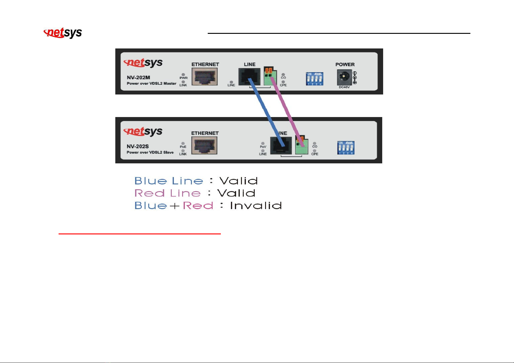
2.4 Connecting the NV-202M and NV-202S
NV-202M power adapters ust be connected first before switch can be powered on. NV-202M/S has one RJ-45 fast
Ethernet port which support connection to Ethernet operation. The devices attached to these ports ust support
auto-MDIX and auto-negotiation or 10Base-T OR 100Base-TX unless they will always operate at half-duplex. NV-202S
fast Ethernet port is used to connect to external power splitter(POE) or build in power splitter of networking devices
such as IP CAM, VOIP, wireless AP, sensor scanner or other power splitter(PD side) at least 15W.
The line port has 1 connector: RJ-45 and ter inal block. It is used to connect fro NV-202M using single pair phone
cable to NV-202S side(point to point solution). Take note that NV-202M/S line port cannot be used at the sa e ti e.
Either RJ-45 port is connected or ter inal block is connected using straight connection (Figure2.1)
Figure2.1: NV-202M/S line orts straight connection
NV-202M/S LAN extender with Remote Power USER’S MANUAL Ver. A.2
10
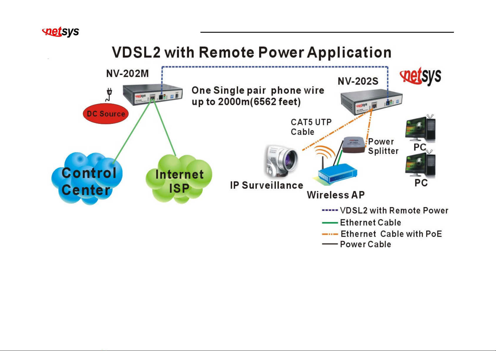
2.5 Connecting the Line / Ethernet Ports
1. The NV-202M/S’ line port supports ax distance of 2k for data service across existing phone wiring. It is
easy-to-use which do not require installation of additional wiring. Every odular phone jack in the ho e can
beco e a port on the LAN. (Figure 2.2)
NV-202M/S LAN extender with Remote Power USER’S MANUAL Ver. A.2
11
Figure 2.2: Master / Slave Ethernet extender with remote ower oint-to- oint a lication
2. Use only twisted pair cable with RJ-45 connectors that confor to Ethernet standard. When inserting a RJ-45 plug,
be sure the tab on the plug clicks into position to ensure that it is properly seated.
NV-202M/S LAN extender with Remote Power USER’S MANUAL Ver. A.2
12
Notes:
1. Be sure each twisted-pair cable (RJ-45) does not exceed 100 eters (328 feet).
2. Line port ust use 22 ~ 26 gauge phone wiring, we do not reco end 28 gauge or above.
3. We advise using Category 3, 4, 5 cables for cable NV-202M/S or router connections to avoid any confusion or
inconvenience in the future when you attached to high bandwidth devices.
4. Be sure phone wiring has been installed before NV-202M and NV-202S powered on.
Cha ter 3. Hardware Descri tion
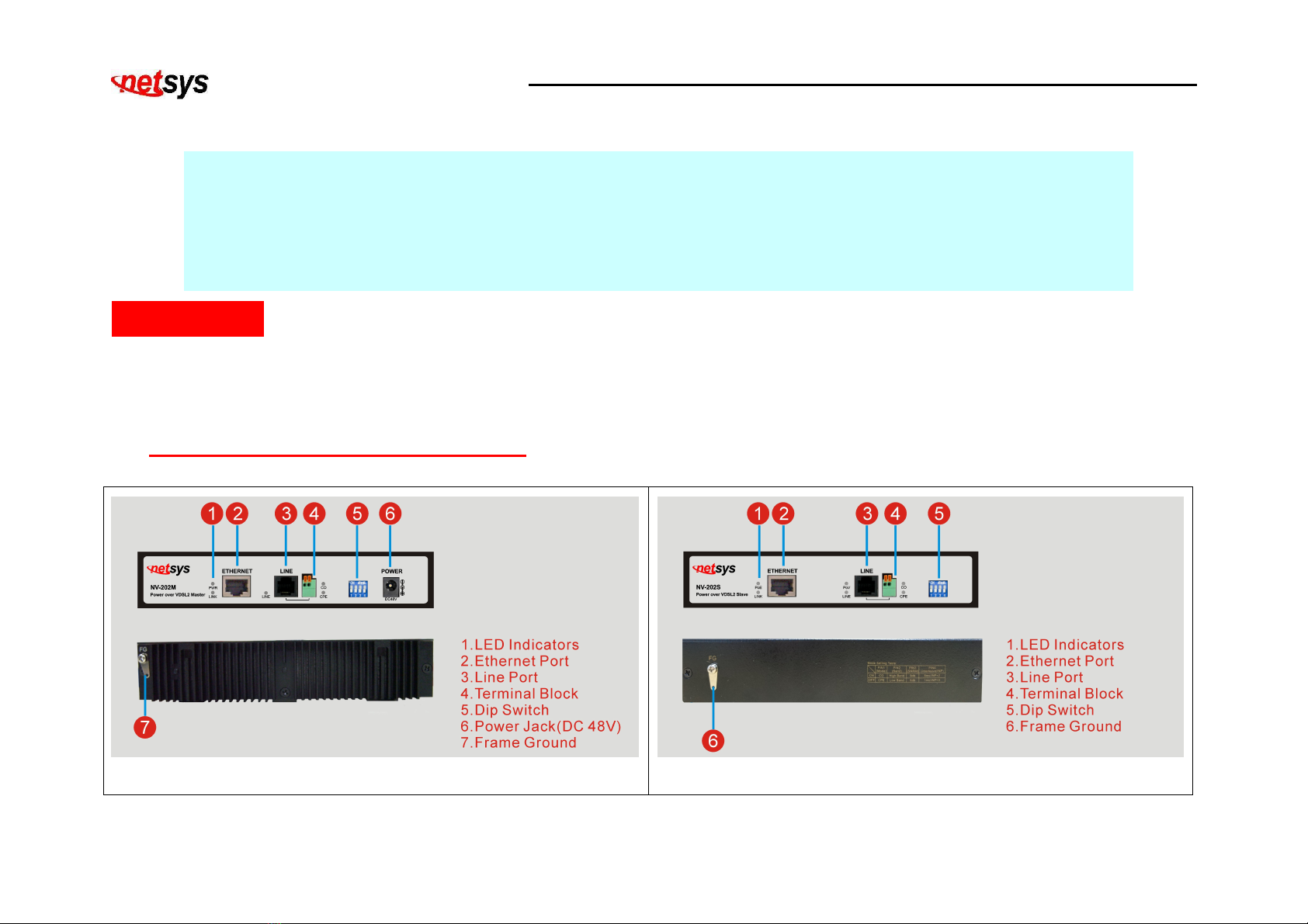
This section describes the i portant parts of the NV-202M/S. It features the front panel and rear connectors.
3.1 NV-202M / NV-202S Detailed View
Figure 3.1: NV-202M detailed view
Figure 3.2: NV-202S detailed view

NV-202M/S LAN extender with Remote Power USER’S MANUAL Ver. A.2
13
3.2 Front Panel
The figure shows the front panel of both NV-202M and NV-202S. (Figure 3.3)
Figure 3.3: Front Panel of NV-202M/S
At a quick glance of the front panel, it is easy to tell if NV-202M/S has power, if it has signal fro its Ethernet RJ-45 port,
if it is either providing or receiving power and if there is line signal on the line port. (Table 3-1)

NV-202M/S LAN extender with Remote Power USER’S MANUAL Ver. A.2
14
Table 3-1: Description of NV-202M/S front interface
Interface
Connector Ty e Descri tion
Line RJ-11 / Ter inal Block For connecting to NV-202M/S both line port over phone wire.
Ethernet RJ-45
For connecting to the networking device for NV-202M. For
connecting to the networking device with power splitter or
connecting to external power splitter for NV-202S.
3.3 Front Indicators
The NV-202M has FIVE LED indicators. The following table shows the description. (Table 3-2)
Table 3-2: LED Indicators Description and Operation
LEDs Color Status Descri tions
On The syste power is nor al and functioning properly.
PWR (Power LED) Green Off The syste power is not ready or has alfunctioned.
On The device has a good Ethernet connection.(Link)
Blinking The device is trans itting / receiving data.(Activity)
LINK Green
Off The LAN is not connected.
LINE(VDSL LINK LED) Green On The Internet or network connection is up.

NV-202M/S LAN extender with Remote Power USER’S MANUAL Ver. A.2
15
Blinking fastly
1.The CO device has detected a CPE device and ready to connect.
2.The device is sending or receiving data.
Off The syste power is not ready or has alfunctioned.
CO (Local Side)
(CO LED) Green On(Steady) Indicate the VDSL2 NV-202M is running at CO(Master) ode.
CPE (Re ote Side)
(CPE LED) Green On(Steady) Indicate the VDSL2 NV-202M is running at CPE(Slave) ode.
The NV-202S has SIX LED indicators. The following table shows the description. (Table 3-3)
Table 3-3: LED Indicators Description and Operation
LEDs Color Status Descri tions
On The power injector had detected the power splitter (IEEE802.3at).
Blinking The power injector had detected a non standard POE.
PoE
(Power over Ethernet LED) Green
Off The power injector has not detected the power splitter.
On The device has a good Ethernet connection.(Link)
Blinking The device is trans itting / receiving data.(Activity)
LINK Green
Off The LAN is not connected.
PoV Green On For NV-202S the device is re ote power link good.

NV-202M/S LAN extender with Remote Power USER’S MANUAL Ver. A.2
16
(Power over VDSL LED) Off The device is not ready or has alfunctioned.
On The Internet or network connection is up.
Blinking fastly
1.The CO device has detected a CPE device and ready to connect.
2.The device is sending or receiving data.
LINE(VDSL LINK LED) Green
Off The syste power is not ready or has alfunctioned.
CO (Local Side)
(CO LED) Green On(Steady)
Indicate the VDSL2 NV-202S is running at CO(Master) ode.
CPE (Re ote Side)
(CPE LED) Green On(Steady)
Indicate the VDSL2 NV-202S is running at CPE(Slave) ode.
3.4 Rear Panel
The following figure shows the rear connectors. (Figure 3.4)
Figure 3.4: Rear connectors of NV-202M/S res ectively

NV-202M/S LAN extender with Remote Power USER’S MANUAL Ver. A.2
17
The following figure shows the DIP switch connection. By switching the trans ission odes, you can obtain a best
trans ission ode to suit with phone line quality or distance or connectivity. (Figure 3.5).
Figure 3.5: DIP switch setting
The following is table of DIP Switch configuration. (Table 3-6)
Table 3-6 DIP Switch Configuration
Pin 1 Pin 2 Pin 3 Pin 4
On/OFF
CO/CPE Mode Band SNRM Interleave / INP
On CO Mode High Band 9db 8 s / INP=2
Off CPE Mode Low band 6db 1 s / INP=0
ON
OFF
NV-202M/S LAN extender with Remote Power USER’S MANUAL Ver. A.2
18
Note:
1. The DIP switch default values are OFF.
2. Please power off NV-202M, before aking any trans ission ode configuration.
TIP(Reference Only):
Interleave delay function is used in digital data trans ission technology to protect the trans ission against noise issue
and data error.
If during transit ore than a certain a ount of data has been lost then the data cannot be correctly decoded. Short bursts
of noise on the line can cause these data packets to beco e corrupt and the NV-202M/S has to re-request data which in turn
can slow down the overall rate at which data is trans itted.
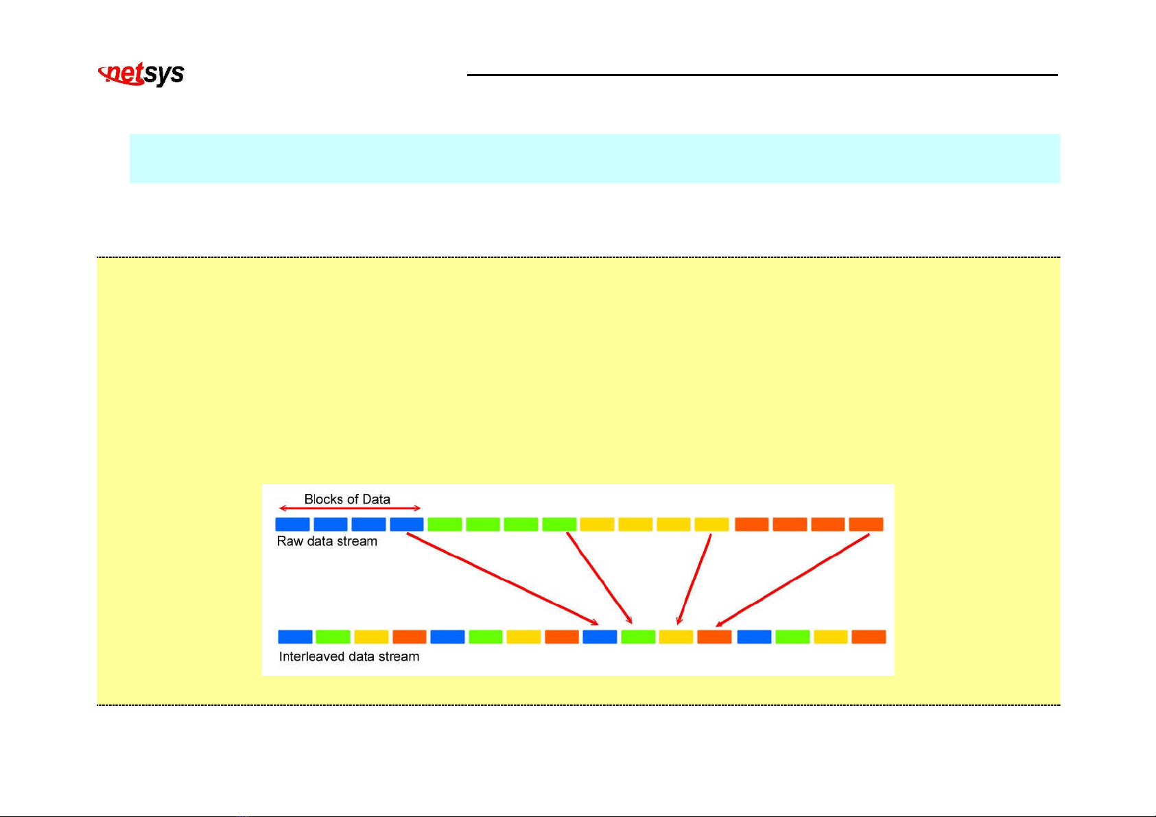
Interleaving is a ethod of taking data packets, chopping the up into s aller bits and then rearranging the so that
once contiguous data is now spaced further apart into a non continuous strea . Data packets are re-asse bled by your
NV-202M/S.
The diagra below is an exa ple of how interleaved traffic is trans itted.
If your line is particularly susceptible to bursts of noise then interleaving should i prove your VDSL2 experience si ply

NV-202M/S LAN extender with Remote Power USER’S MANUAL Ver. A.2
19
because if you lose a whole batch of data then this could cause your NV-202M/S to loose sync with the exchange.
Using Interleaving, the NV-202M/S is able to re-asse ble the data or if necessary just re-request the part of the data that it is
unable to recover. By increasing the interleave depth of each ports that are susceptible to noise, this will i prove error
perfor ance and stability of arginal lines.
INP (Im ulse Noise Protection): I pulse noise in ulticarrier co unication syste s behaves effectively as a odulating
signal that controls the first o ent of the background Gaussian noise. The co posite noise, which is the aggregate of the
Gaussian noise and i pulse noise, has a probability density function that is conditionally Gaussian with non-zero average,
hence referred to as biased-Gaussian. The BER-equivalent power of the co posite noise source is defined as the power of a
pure Gaussian noise source that yields the sa e bit-error rate (BER). The BER-equivalent noise for a biased-Gaussian noise
is si ply the a plified version of the underlying Gaussian noise source. The a plification factor is derived fro the
characteristics of the i pulse interference. Any bit-loading algorith designed for Gaussian noise sources is also applicable to
biased-Gaussian noise sources provided that the BER-equivalent SNR is used in place of the easured SNR.
SNRM (Signal to Noise Ratio Margin): It's very si ilar to a conversation at a party and it's dealt with in the sa e way; we naturally
account for both distance fro the other person and the a ount of background noise. When we do we don't just talk loud enough to
be heard, we speak a bit louder waiting for the idiot with the stupid, loud laugh to start up again. We add a bit extra on to ake sure
we're louder than the average change in background noise.
That ratio is a ajor factor in deter ining the connection speed, as the higher the ratio the higher the possible speed. The SNRM is a
argin which by which the noise level can rise before connection is lost.
This manual suits for next models
1
Table of contents
Other netsys Extender manuals


