netsys NV-700L User manual

N
N
NV
V
V-
-
-7
7
70
0
00
0
0L
L
L
V
V
VD
D
DS
S
SL
L
L2
2
2
S
S
Si
i
in
n
ng
g
gl
l
le
e
e
M
M
Ma
a
as
s
st
t
te
e
er
r
r
M
M
Mo
o
od
d
de
e
em
m
m
U
U
US
S
SE
E
ER
R
R’
’
’S
S
S
M
M
MA
A
AN
N
NU
U
UA
A
AL
L
L

NV-700L VDSL2 Single Master Modem USER’S MANUAL Ver. A.2
1
Copyrig t
Copyright © 2018 by National Enhance Technology Corp. All rights reserved.
Trademarks
NETSYS is a trade ark of National Enhance Technology Corp.
Other brand and product na es are registered trade arks or trade arks of their respective holders.
Legal Disclaimer
The infor ation given in this docu ent shall in no event be regarded as a guarantee of conditions or characteristics. With respect
to any exa ples or hints given herein, any typical values stated herein and/or any infor ation regarding the application of the
device, National Enhance Technology Corp. hereby disclai s any and all warranties and liabilities of any kind, including without
li itation warranties of non-infringe ent of intellectual property rights of any third party.
Statement of Conditions
In the interest of i proving internal design, operational function, and/or reliability, NETSYS reserves the right to ake changes to
the products described in this docu ent without notice. NETSYS does not assu e any liability that ay occur due to the use or
application of the product(s) or circuit layout(s) described herein.
Maxi u signal rate derived fro IEEE Standard specifications. Actual data throughput will vary. Network conditions and
environ ental factors, including volu e of network traffic, building aterials and construction, and network overhead, lower actual
data throughput rate. Netsys does not warrant that the hardware will work properly in all environ ents and applications, and akes
no warranty and representation, either i plied or expressed, with respect to the quality, perfor ance, erchantability, or fitness for
a particular purpose. Make sure you follow in line with the environ ental conditions to use this product.

NV-700L VDSL2 Single Master Modem USER’S MANUAL Ver. A.2
2
Safety Warnings
For your safety, be sure to read and follow all warning notices and instructions before using the device.
DO NOT open the device or unit. Opening or re oving the cover ay expose you to dangerous high voltage points or other
risks. ONLY qualified service personnel can service the device. Please contact your vendor for further infor ation.
Use ONLY the dedicated power supply for your device. Connect the power to the right supply voltage (110V AC used for
North A erica and 230V AC used for Europe. NV-700L supports 12 VDC power input).
Place connecting cables carefully so that no one will step on the or stu ble over the . DO NOT allow anything to rest on
the power cord and do NOT locate the product where anyone can work on the power cord.
DO NOT install nor use your device during a thunderstor . There ay be a re ote risk of electric shock fro lightning.
DO NOT expose your device to da pness, dust or corrosive liquids.
DO NOT use this product near water, for exa ple, in a wet base ent or near a swi ing pool.
Connect ONLY suitable accessories to the device.
Make sure to connect the cables to the correct ports.
DO NOT obstruct the device ventilation slots, as insufficient air flow ay har your device.
DO NOT place ite s on the device.
DO NOT use the device for outdoor applications directly, and ake sure all the connections are indoors or have waterproof
protection place.
Be careful when unplugging the power, because it ay produce sparks.
Keep the device and all its parts and accessories out of the reach of children.
Clean the device using a soft and dry cloth rather than liquid or ato izers. Power off the equip ent before cleaning it.
This product is recyclable. Dispose of it properly.

NV-700L VDSL2 Single Master Modem USER’S MANUAL Ver. A.2
3
Attention:
Be sure to read t is manual carefully before using t is product. Especially Legal Disclaimer, Statement
of Conditions and Safety Warnings.
NV-700L is a VDSL2 Master Mode that leverages the extraordinary bandwidth pro ise of VDSL2 ( ax. 100Mbps sy etric)
technology, the next step in the delivery of new high-speed Internet applications in co ercial environ ents. Quick, easy,
econo ical to install and aintain, the NV-700L works over existing copper wire infrastructure. NV-700L is a CO(Central Office)
device. And co pitable with the NV-720R CPE(Custo er-pre ises equip ent).
NV-700L will allow operators worldwide to co pete with cable andsatellite operators by offering services such as HDTV, VOD,
videoconferencing, high speed Internet access and advanced voice services including VoIP, over a standard copper
telephone cable. NV-700L is seen by any operators as an ideal acco pani ent to a FTTP rollout, where for instance fiber optic is
supplied direct to an apart ent block and fro there copper cable is used to supply residents with high-speed VDSL2.
Caution:
The NV-700L is for indoor applications only. This product does not have waterproof protection, please do not use in outdoor
applications.

NV-700L VDSL2 Single Master Modem USER’S MANUAL Ver. A.2
4
Table of Contents
COPYRIGHT.......................................................................................................................................................................................................................................................... 1
1.1
C
HECK
L
IST
.................................................................................................................................................................................................................................................... 7
CHAPTER 2. INSTALLING THE MODEM ........................................................................................................................................................................................................ 8
2.1
H
ARDWARE
I
NSTALLATION
............................................................................................................................................................................................................................. 8
2.2
P
RE
-
INSTALLATION
R
EQUIREMENTS
................................................................................................................................................................................................................ 8
2.3
G
ENERAL
R
ULES
............................................................................................................................................................................................................................................. 9
2.4
C
ONNECTING THE
RJ-11
/
RJ-4
P
ORTS
........................................................................................................................................................................................................ 10
2.5
VDSL2
A
PPLICATION
.................................................................................................................................................................................................................................. 11
CHAPTER 3. HARDWARE DESCRIPTION ................................................................................................................................................................................................... 13
3.1
F
RONT
P
ANEL
................................................................................................................................................................................................................................................ 14
3.2
F
RONT
I
NDICATORS
....................................................................................................................................................................................................................................... 14
3.3
R
EAR
P
ANEL
............................................................................................................................................................................................................................................... 16
CHAPTER 4. CONFIG RE THE NV-700L VIA WEB BROWSER............................................................................................................................................................... 18
4.1
BASIC
S
ETUP
............................................................................................................................................................................................................................................ 19
Login web age.......................................................................................................................................................................................................................................... 19
Dis lay status............................................................................................................................................................................................................................................ 20
4.2
S
YSTEM
S
ETUP
........................................................................................................................................................................................................................................... 21
System–> Configuration Backu ......................................................................................................................................................................................................... 21
System-> Configuration Restore.......................................................................................................................................................................................................... 22
System->U date Software ..................................................................................................................................................................................................................... 23

NV-700L VDSL2 Single Master Modem USER’S MANUAL Ver. A.2
system->Account Management ............................................................................................................................................................................................................ 24
system->Account Management - Log Level...................................................................................................................................................................................... 25
System->Service control ........................................................................................................................................................................................................................ 26
System->CWNP->TR-069 Settings ....................................................................................................................................................................................................... 27
System->Restore Default Setting......................................................................................................................................................................................................... 29
4.3
S
TATUS
S
ETUP
............................................................................................................................................................................................................................................ 30
Status ->LAN Network............................................................................................................................................................................................................................. 30
Status->LAN-> Ethernet.......................................................................................................................................................................................................................... 31
Status->WAN Statistics........................................................................................................................................................................................................................... 32
Status->LAN Statistics ............................................................................................................................................................................................................................ 33
Status->ARP .............................................................................................................................................................................................................................................. 34
4.4
X
DSL
SETUP.............................................................................................................................................................................................................................................. 3
Xdsl ->DSL STATUS ................................................................................................................................................................................................................................. 35
Xdsl-DSL Config ....................................................................................................................................................................................................................................... 36
VDSL Config Overview............................................................................................................................................................................................................................ 37
4.5
LAN
S
ETUP
................................................................................................................................................................................................................................................. 38
LAN >IPV4 Configuration ....................................................................................................................................................................................................................... 38
LAN->IPv6 Configuration: ...................................................................................................................................................................................................................... 39
4.6
Q
OS
SETUP ............................................................................................................................................................................................................................................... 40
Qos ->Qos Queue..................................................................................................................................................................................................................................... 40
4.7
A
PPLICATION
S
ETUP
................................................................................................................................................................................................................................... 41
A lication->Telnet Service Setu ...................................................................................................................................................................................................... 41
A lication-> SSH Service..................................................................................................................................................................................................................... 42
A lication->Printer Share .................................................................................................................................................................................................................... 43

NV-700L VDSL2 Single Master Modem USER’S MANUAL Ver. A.2
6
A lication->Multimedia Share ............................................................................................................................................................................................................ 44
A lication->Dynamic DNS ................................................................................................................................................................................................................... 45
A lication->UPnP................................................................................................................................................................................................................................... 46
A lication->multicast IGMP setting .................................................................................................................................................................................................. 47
A lication->Multicast MLD .................................................................................................................................................................................................................. 48
APPLICATION->SNMP ............................................................................................................................................................................................................................ 49
4.8
USB
SETUP
................................................................................................................................................................................................................................................. 2
USB-Storage Device Info........................................................................................................................................................................................................................ 52
USB->Samba Service .............................................................................................................................................................................................................................. 53
USB-> FTP Server .................................................................................................................................................................................................................................... 54
USB-> FTP Client...................................................................................................................................................................................................................................... 55
USB-> TFTP Server .................................................................................................................................................................................................................................. 57
APPENDIX A: CABLE REQ IREMENTS ...................................................................................................................................................................................................... 58
APPENDIX B: PROD CT SPECIFICATION.................................................................................................................................................................................................. 61
APPENDIX C: TRO BLESHOOTING ............................................................................................................................................................................................................ 65
APPENDIX E: COMPLIANCE INFORMATION............................................................................................................................................................................................ 73
WARRANTY......................................................................................................................................................................................................................................................... 76
CHINESE SJ/T 11364-2014............................................................................................................................................................................................................................... 77
NV-700L VDSL2 Single Master Modem USER’S MANUAL Ver. A.2
7
C apter 1. Unpacking Information
1.1 C eck List
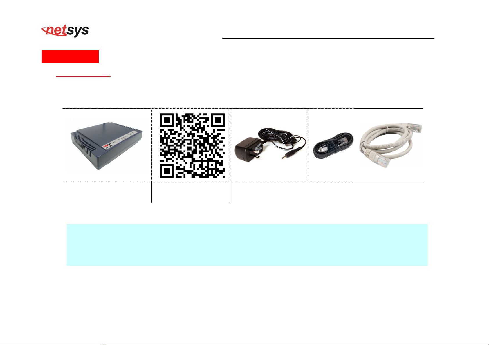
Thank you for choosing Netsys NV-700L Before installing the router, please verify the contents inside the package.
Package Contents:
1 x VDSL2 CO Mode 1 x QR code for user’s
anual hyperlink.
Accessory Kit : 1 x Ethernet Cable, 1 x Phone wire , 1 x
DC12V Power Adapter
Notes:
1. Please infor your dealer i ediately for any issing or da aged parts. If possible, retain the carton including the
original packing aterials. Use the to repack the unit in case there is a need to return for repair.
2. Do not use sub-standard power supply. Before connecting the power supply to the device, be sure to check
co pliance with the specifications. The NV-700L uses a DC12V/1A or above Switching power supply.

NV-700L VDSL2 Single Master Modem USER’S MANUAL Ver. A.2
8
C apter 2. Installing t e Modem
2.1 Hardware Installation
This chapter describes how to install the ode , and establish the network connections. The NV-700L ay be
installed on any level surface (e.g. a table or shelf). However, please take note of the following ini u site
require ents before you begin. T e NV-700L as 2 pre-installed rubber feet.
2.2 Pre-installation Requirements
Before you start the actual hardware installation, ake sure you can provide the right operating environ ent, including
power require ents, sufficient physical space, and proxi ity to other network devices that are to be connected.
Verify the following installation require ents:
• Power require ents: DC 12 V / 1A
• The ode should be located in a cool dry place, with at least 10cm/4in of space at the front and back for
ventilation.
• Place the ode away fro direct sunlight, heat sources, or areas with a high a ount of electro agnetic
interference.
• Check if the network cables and connectors needed for installation are available.
• Do not install phone lines strapped together with AC power lines, or telephone office line with voice signal.
• Avoid installing this device with radio a plifying stations nearby or transfor er stations nearby.
• Please note that the voice spectru allowed by the NV-700L internal splitter is 0 KHz ~ 120 KHz.

NV-700L VDSL2 Single Master Modem USER’S MANUAL Ver. A.2
9
2.3 General Rules
Before aking any connections to the ode , please note the following rules:
• Et ernet Port interface : RJ-45
All network connections to the ode Ethernet port ust be ade using Category 5 UTP/STP or above for
100 Mbps, Category 3, 4 UTP for 10Mbps.
No ore than 100 eters of cabling ay be use between the MUX or HUB and an end node.
• VDSL2 Port interface : RJ-11 & Terminal block combo
All network connections to the RJ-11/ ter inal block(sharing port) ust use 24~26 gauge with single
twisted pair phone wire.
We do not recommend the use of the 28 gauge phone wire or above.
The RJ-11 is an 6P2C connector, two of which are wired. The ode uses the center two pins. The pin out
assign ent for these connectors is presented below.
Please note that the line port is no polarity, therefore user can reverse the two wires of the phone cable
when installed.
RJ-11 Pin out Assign ents
Pin# MNEMONIC FUNCTION
1 NC Unused
2 NC Unused
3 DSL Used
4 DSL Used
5 NC Unused
6 NC Unused
NV-700L VDSL2 Single Master Modem USER’S MANUAL Ver. A.2
10
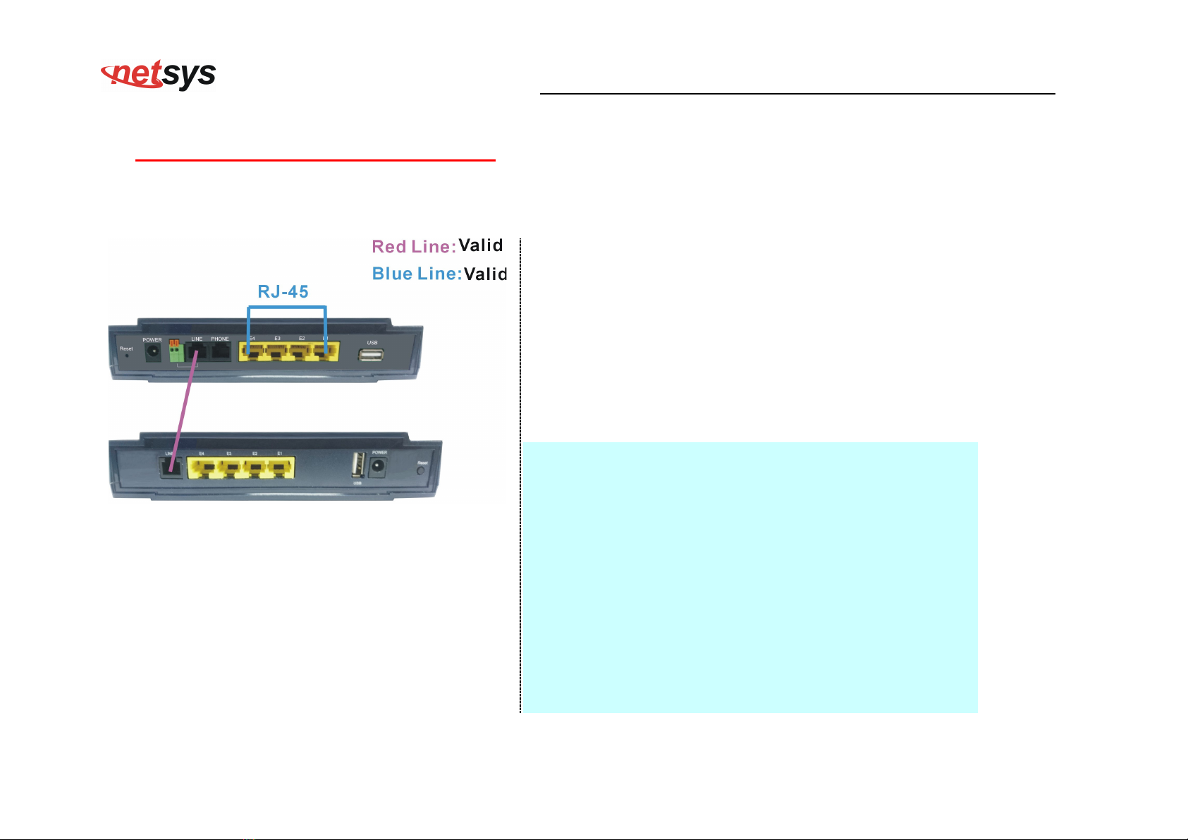
2.4 Connecting t e RJ-11 / RJ-45 Ports
The line port have 1 connector: RJ-11 . It is used to connect with NV-700L (CO) over a single pair phone wire to NV-720R
CPE(Slave) side (point to point application). (Figure 2.1)
Figure 2.1 NV-700L line ports straig t connection
When inserting a RJ-11 plug, ake sure the tab on the
plug clicks into position to ensure that it is properly
seated.
Do not plug a RJ-11 phone jack connector into the
Ethernet port (RJ-45 port). This ay da age the
ode . Instead, use only twisted-pair cables with RJ-45
connectors that confor to Ethernet standard.
Notes:
1. Be sure each twisted-pair cable (RJ-45 Ethernet cable)
does not exceed 100 eters (333 feet).
2. We advise using Category 5~7 UTP/STP cables for
aking Ethernet connections to avoid any confusion or
inconvenience in the future when you attach high
bandwidth devices.
3. Use 24 ~ 26 gauge twisted pair phone wiring, we do not
reco end 28 gauge or above.
4. Be sure phone wire has been installed before the
NV-700L boot.
5. Do not connect Line port with RJ-11 and Ter inal block
to two CPE ode .

NV-700L VDSL2 Single Master Modem USER’S MANUAL Ver. A.2
11
2.5
VDSL2 Application
First a quick overview on a co plete setup of VDSL2 CO/CPE Mode .
NV-700L/NV-720R is a ode leverages the extraordinary bandwidth pro ise of VDSL2( ax 100Mbps Sy etric) technology
(Figure 2.2)
Figure 2.2 NV-700L application

NV-700L VDSL2 Single Master Modem USER’S MANUAL Ver. A.2
12
2.5.1 Connect t e NV-700L and t e NV-720R to t e Line
The objective for VDSL2 is to pass high speed data over a twisted pair cable. In the setup, connect NV-700L to NV-720R through
phone wire(24~26 AWG) or line si ulator or any other hardware representation of a cable network, with or without noise
injection and crosstalk si ulations.
2.5.2 Connect t e NV-700L and t e NV-720R to LAN Devices
In the setup, usually an Ethernet tester serves as a representation of the LAN side as well as a representation of the WAN side.
2.5.3 Run Demos and Tests
The Ethernet tester ay send data downstrea as well as upstrea . It also receives the data in order to check the integrity of the
data trans ission. Different data rates can be tested under different line conditions
NV-700L VDSL2 Single Master Modem USER’S MANUAL Ver. A.2
13
C apter 3. Hardware Description
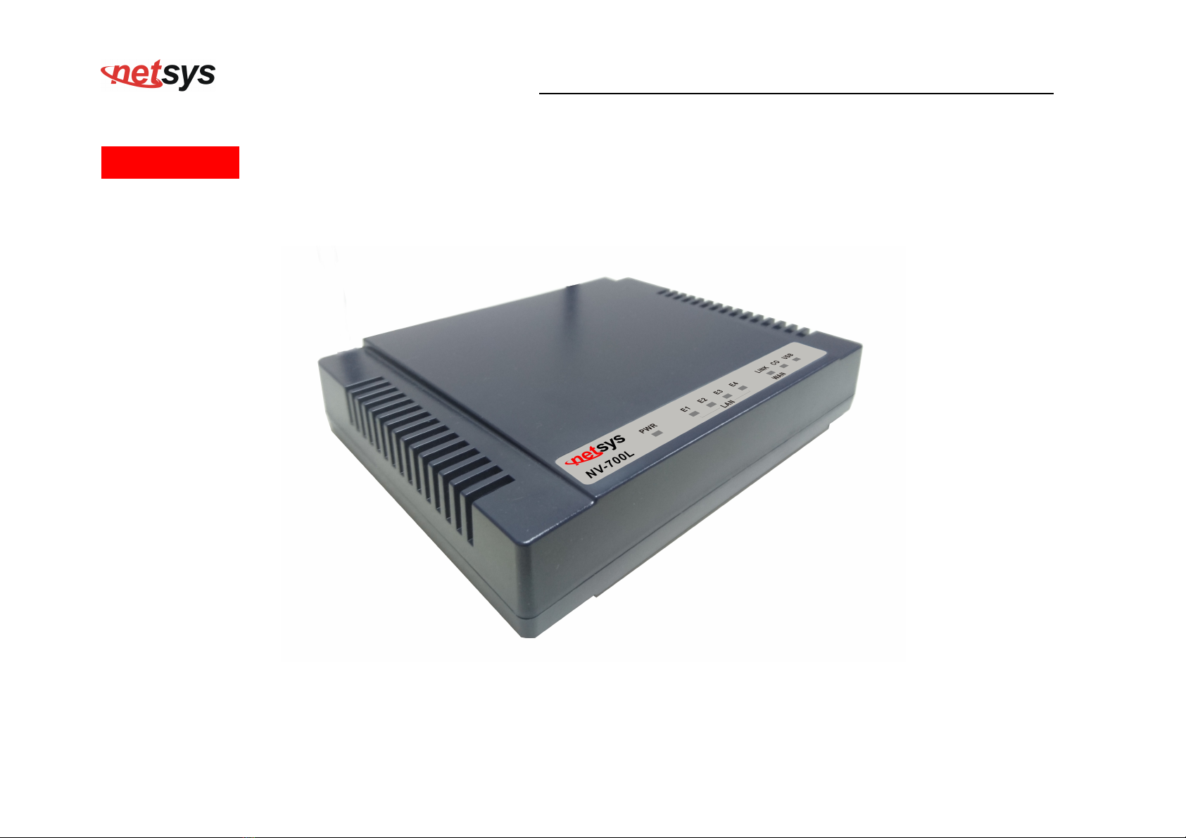
This section describes the i portant parts of the vdsl2 Mode It features the front panel and rear panel.
NV-700L Outward
NV-700L VDSL2 Single Master Modem USER’S MANUAL Ver. A.2
14
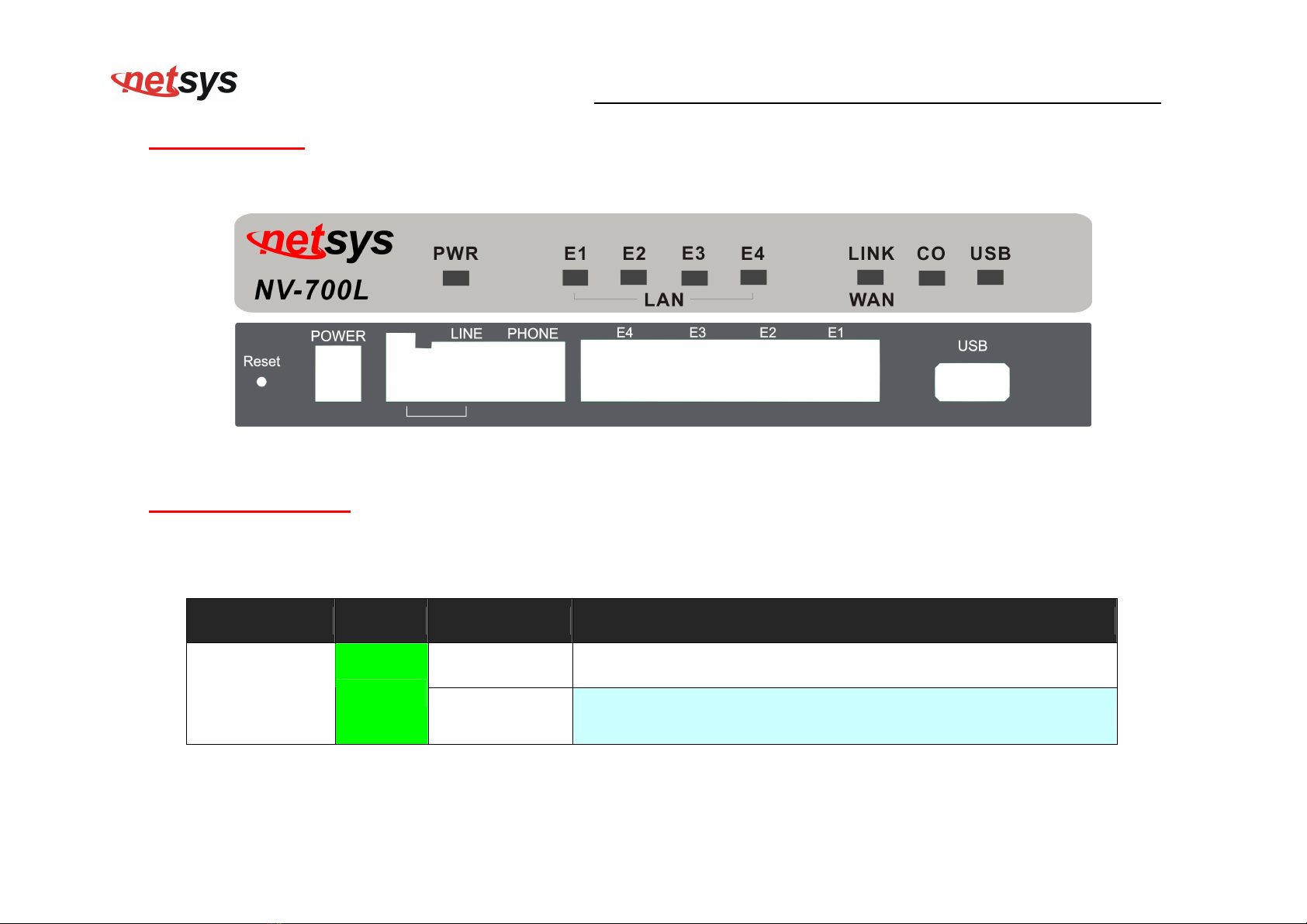
3.1 Front Panel
The figure shows the front panel. (Figure 3.1)
Figure 3.1 Front Panel(NV-700L)
3.2 Front Indicators
The Mode has Seven LED indicators. The following Table shows the description. (Table 3-1)
Table 3-1 LED Indicators Description and Operation
LED Color Status Descriptions
On(Steady) Lights to indicate that the VDSL2 ode had power
PWR
(Power LED) Green
Off The device is not ready or has alfunctioned.

NV-700L VDSL2 Single Master Modem USER’S MANUAL Ver. A.2
1
LED Color Status Descriptions
On(Steady) The device has a good Ethernet connection.
Blinking The device is sending or receiving data.
E1 ~ E4
(Ethernet LED)
Green
Off The LAN is not connected or has alfunctioned.
On(Steady) The Internet or network connection is up.
Fast Blinking 1. The CO device has detected a CPE device and ready to connect.
2. The device is sending or receiving data.
LINK
(VDSL2 LED) Green
Off The Internet or network connection is down.
On (Steady) The device has a good USB dongle connection.
USB Green
Off The device is not ready or has alfunctioned.
CO Green On (Steady) The device has a good Master connection.
Note:
It is nor al for the connection between two Mode s to take up to 3 inutes, due to NV-700L/NV-720R to establish a link echanis
in auto-negotiation, with detects and calculates CO and CPE both PBO and PSD level, noise levels and other argu ents for getting
a better connection.

NV-700L VDSL2 Single Master Modem USER’S MANUAL Ver. A.2
16
3.3 Rear Panel
The following figure shows the rear panel. (Figure 3.2)
Figure 3.3 Rear Panel
And the table shows the description. (Table 3-2)
Table 3-2 Description of the ode rear connectors
Type Connector Description
Reset Tact switch Button
The reset buttons allows users to reboot the VDSL2 or load the default
settings.
Press and old for 1-5 seconds: Reboot t e VDSL2 Modem
Press over 5 seconds: Load t e default settings
Power DC Jack External switching Power Adapter: Input: AC 85~240Volts/50~60Hz.
Output: DC 12V/1A.
Line RJ-11 For connecting to a VDSL2 device.

NV-700L VDSL2 Single Master Modem USER’S MANUAL Ver. A.2
17
Type Connector Description
phone RJ-11 For connecting to the POTS equip ent or ISDN.
Ethernet
(E1-E4) RJ-45 For connecting to an Ethernet equipped device.
USB USB2.0 Type A For connecting to the USB dongle.
Before user installed power and device, please read and follow t ese essentials:
Use separate paths to route wiring for power and devices. If power wiring and device wiring paths ust cross, ake sure the
wires are perpendicular at the intersection point.
Note:
Do not run signal or co unications wiring and power wiring through the sa e wire conduit. To avoid interference, wires with
different signal characteristics should be routed separately.
You can use the type of signal trans itted through a wire to deter ine which wires should be kept separate. The rule of thu b
is that wiring sharing si ilar electrical characteristics can be bundled together.
You should separate input wiring fro output wiring.
We reco end that you ark all equip ent in the wiring syste .

NV-700L VDSL2 Single Master Modem USER’S MANUAL Ver. A.2
18
C apter 4.
Configure t e NV-700L Via Web Browser
The NV-700L provides a built-in HTML based anage ent interface that allows configuration of the NV-700L via
Internet Browser. Best viewed using Chro e or Firefox browsers.
In order to use the web browser to configure the device, you ay need to allow:
• Web browser pop-up windows fro your device. Web pop-up blocking is enabled by default in windows XP
SP2 or above.
• Java Scripts. (Enabled by default)
• Java per issions. (Enabled by default)
Launch your web browser and input the IP address 192.168.16.249 (NV-700L) in the Web page.
Following section user can find default userna e and password.
NV-700L VDSL2 Single Master Modem USER’S MANUAL Ver. A.2
19
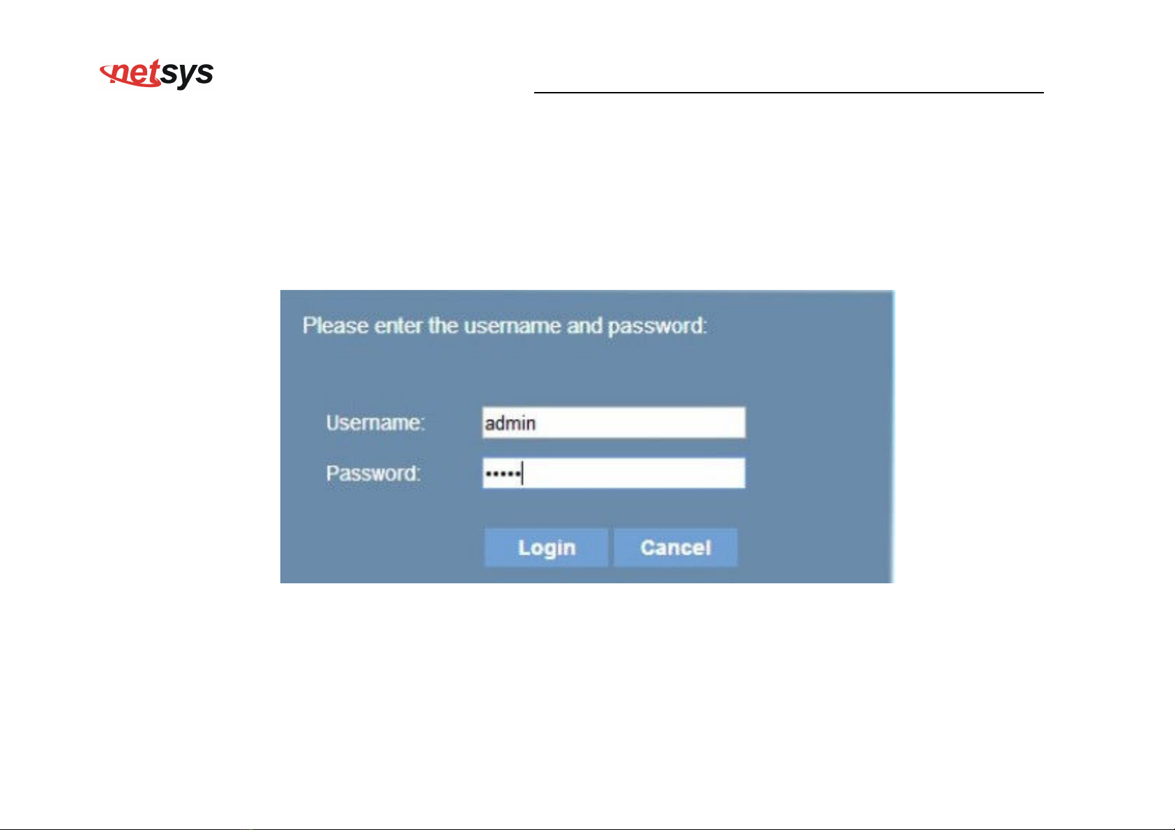
4.1 BASIC Setup
Login webpage
The IP address is 192.168.16.249 , username and password are admin.
Figure 4.1 Login Password
Table of contents
Other netsys Modem manuals


