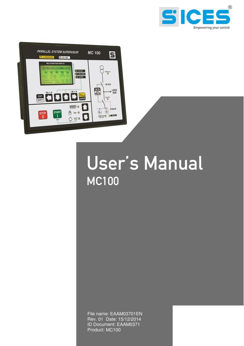
Sices DIPOT User manual

Filename: EAAM024505EN.docx
Rev. 05 Date: 07/05/2013
ID Document: EAAM0245
Product: DIPOT

ii User’s Manual
1. General Information.................................................................................................3
2. Characteristics.........................................................................................................3
2.1 Output...................................................................................................................3
2.2 Power input...........................................................................................................4
2.3 Controls and function............................................................................................4
2.4 Digital inputs.........................................................................................................6
2.5 Analog Inputs........................................................................................................6
2.6 Adjustments..........................................................................................................7
3. Voltage isolator mode .............................................................................................8
4. Connections.............................................................................................................9
4.1 RS485 interface version connections .................................................................10
4.1.1 Modbus addresses and communication protocol .........................................10
4.1.2 ModBus address list.....................................................................................11
4.2 CAN BUS version connection.............................................................................14
4.2.1 CAN BUS communication ............................................................................14
5. Dimensions ............................................................................................................16

User’s Manual 3
This document describes the technical and functional characteristics and how to use the DIPOT board.
The available models are identified by the following codes:
1. E6102094300xx : DIPOT RS485 IN 0÷5V/IN 0÷10V
2. E6102094301xx : DIPOT RS485 IN TEMP./PRESS. VDO
3. E6102094302xx : DIPOT CANBUS IN 0÷5V/IN 0÷10V
4. E6102094303xx : DIPOT CANBUS IN TEMP./PRESS. VDO
Thanks to its versatility, the "DIPOT" device lets you connect most products (Speed regulators, Voltage
regulators, Power factor controllers, etc.) that require a voltage or current input, to suit their variation and
management specifications. The output for piloting the boards is managed by a microcontroller that
controls the regulation of an output proportional current loop (which can be converted into a voltage
output using a simple resistance).
The output can be regulated and piloted with UP and DOWN digital inputs, or by modifying the Modbus
protocol registry value via RS485 connection or CANBUS J1939 connection to our generator
management boards DST4601, DST4601PX, DST4400, etc.
2.1
On all DIPOT models, the regulation of the Current Loop can be selected using three configurations of
dip-switches:
from 0 to +20 mA
from -10mA to +10mA
from -20mA to +20 mA
Using one of the current adjustable outputs we can create a voltage output by connecting a resistor to
pins 2 and 3 of connector J1.
The current loop device output is between pins +4, +3 for the positive, and pins -2, -1 of J1 for the
negative. The resistor can be connected to pin 2and pin 3of J1 .
Warning: Carefully consider the resistor and the dip-switch configuration, as the max.
voltage range is ± 11V.
Here are some examples:
Example 1:
Voltage required: min. -6V to max. +6 V.
Select ± 20mA
The resistance to use is:
300
02,06A
V
I
V
R
The dissipation power of the resistor must be at least:
WAVIVP 12,002,0*6*
The resistor to be used will be 300ohm - 1/4W

4 User’s Manual
Example 2:
Voltage required: min. 0V to max. 11 V.
Select ± 20mA
The resistance to use is:
550
02,011 A
V
I
V
R
The dissipation power of the resistor must be at least:
WAVIVP 22,002,0*11*
The resistor to be used will be 550ohm - 1/4W
2.2
Connector J5 is used for the power input; input voltage can be either 12 or 24VDC, with a self-rearming
internal fuse. The device is protected by input polarity switching.
The maximum current absorption is approximately 80 mA at a voltage of 10V. The input voltage range
is between 7.5 and 32 VDC.
Configuration:
-J5 –PIN 1: positive input
-J5 –PIN2: negative input
-J3 –PIN6: Ground (cable screens)
Wiring Diagram:
The DIPOT board has several dip switches, which let you set the specific functions of the device, the
current loop value and the properties of the serial port.
The SWE switch is an 8-way dip switch for setting the following specific functions of the product:
DIP 1-4 (Communication address: assign the modbus address to the device (in the CANBUS
version, the communication address is fixed)

User’s Manual 5
DIP 5(analog on CANBUS): enables/disables transmission via Can bus of the water temperature
and oil pressure sensors connected to the analog inputs of the DIPOT module (connector J2). In
the Can Bus version of the receiving device, the Can is always enabled, regardless of the state of
this switch, if SWE dip 7 is ON (REMOTE CONTROLS).
DIP 6 (CCW/CW): lets you switch the current loop output in relation to data control (and then
switch from CW to CCW operating mode). In CW mode, the request with a CANBUS/Modbus
message or from the UP button, for an increment in the command, will result in a drop in the value
of the output current while in CCW mode, the request with a CANBUS/Modbus message or from
the DOWN button, for a decrease in the command, will result in an increase in output current.
DIP 7 (REMOTE/LOCAL CONTROL): in "Local" mode the up/down/reset buttons are acquired
and let you change the current loop output value. In "Remote" mode, the current-loop output value
is determined by the CANBUS or Modbus command. With version RS485 in "Remote" mode, the
value of the MIN, MAX, RESET and RAMP trimmer is set in the "Holding register.
DIP 8(Rpm1500/1800 from CANBUS/DIGITAL INPUT): determines if the nominal speed of the
motor (1500 or 1800 rpm) is automatically detected by the CANBUS or digital input J3-2. (If the
input is active, the nominal speed is 1800 rpm, if the input is inactive the nominal speed is 1500
rpm).
Switch SWD is a 4-way switch and sets the properties of the available serial port on stereo jack connector
J6 and connector J4:
DIP 1 (120R ON/OFF): lets you connect/disconnect the 120R termination resistor on serial port
RS485 of J6 (only if necessary and if the port is set as RS485).
DIP 2 (Enable/disable Serial port): enables/disables the serial port on stereo jack J6.
In the versions with isolated RS485 (E6102094300xx and E6102094301xx) serial port of connector J4
is shared with connector J6. Use SWD dip 2 to select which port should be used. The serial ports on J4
and J6 cannot operate simultaneously. If the serial port is used on connector J6, disconnect the female
connector on J4.
In versions with CANBUS (E6102094020xx and E6102094303xx) the serial port on connector J6 is
always available.
DIP 3 (RS232/RS485): configures the serial port on Stereo jack J6 as RS232 or RS485 (not
isolated).
DIP 4 (9600/19200 Bd): sets the baud rate used by the serial port on Jack (J6) and also that of
isolated RS485 serial port (J4) if the product is version RS485.
The SWB switch is a 2-way switch and sets the scale of the current loop used:
from 0 to +20 mA SWB-1 OFF SWB-2 OFF
from -10mA to +10mA SWB-1 ON SWB-2 ON
from -20mA to +20 mA SWB-1 ON SWB-2 OFF
The SWC switch is a 4-way switch that lets you enable the voltage insulator function (Setting ON on
switch no. 1).

6 User’s Manual
The output value of connector J1 (current loop) can be controlled by three digital inputs (connector J3),
optically isolated. To control, connect the respective input terminal to the insulated positive after
connecting the insulated negative to the common terminal (J5-1). There are a total of 5 contacts:
Pin 1 of J5 COMMON: common negative of optoinsluated inputs
PIN 2 of J5 SPARE/SPEED: only used in CANBUS version to select the nominal speed
(1500 or 1800 rpm) of the engine (if SWE switch 8 is ON ).
PIN 3 of J5 RESET: resets the output to the set value using the RESET TRIMMER
PIN 4 of J5 DOWN:controls the decrease in the output value to the value set with the MIN
trimmer
PIN 5 of J5 UP: controls the increase in the output value to the value set with the MAX
trimmer
The reset command resets the current to the set output value with RESET TR2 trimmer. Activating the
UP and DOWN controls respectively increases or decreases the current value if in CW mode (dip 6 of
SWE OFF), inverted in CCW mode (dip 6 of SWE ON), to the maximum and minimum values adjustable
using the MAX TR3 and MIN TR4 trimmers. Every activation of an UP or DOWN control produces a step
variation in the current value; keeping the control pressed produces a continuous increase/decrease,
with the speed set by trimmer TR1 RAMP (linear resistance ramp-duration of command).
The green LED on the front of the device indicates an order of magnitude for the output value:
LED flashing slowly (50% on and 50% off): minimum output value
As the output value increases so does the frequency of the flashing (50% on and 50% off)
Led on with short intermittent flashes off (90% on 10% off): max. output value.
2.5
The DIPOT board implements two analog inputs, which can be of two types depending on the model:
Analog inputs 0..5V and 0..10V
VDO pressure transducer (0 .. 10bar) and temperature (0 .. 150 ° C) analog inputs
The analog inputs can be measured differentially as they have separate grounds, to avoid non-
equipotential problems with the input ground point of the signal and the input ground of the device.
However, the potential difference between the input ground of the signal and that of the DIPOT input
cannot be more than 1.5 V; over this level, the measurement is imprecise due to the saturation of the
device amplifiers. Considering the high impedance of the measurement inputs, a screened cable should
be used with very long connections. If the ground connections of the inputs aren't used, the ground of
reference is the device power input.
In the case of configuration for pressure and temperature transducer inputs, the two grounds of the
inputs (J2 pin 3 and pin 1) should not be connected.
Since the resistance of the transducers is relatively low, a screened cable isn't required.
notes: Since the conversion between VDO and VEGLIA Borletti transducers involves a
recalibration of the device, this must be done by SICES Ltd.
Analog values acquired by the device are available in the Modbus registers on port RS485 or with SAE
J1939 CAN BUS.

User’s Manual 7
Four settings can be adjusted on the device using the trimmers on the front:
TR1 - RAMP: adjusts the linear increment ramp for the value/duration of the command;
corresponds to the increment/decrement speed of the value with the respective controls enabled.
Turning clockwise increases the rapidity of the increment, which decreases vice versa counter-
clockwise. The total time of the range can be adjusted from 4 seconds to 120 seconds.
TR2 - RESET: adjusts the value after a RESET command; between MIN and MAX value:
normally corresponds to 50% of the output (if output is set to +/- 10 mA the reset value is 0 mA)
TR3 - MIN: adjusts the minimum value obtainable with DOWN command; turning the trimmer
clockwise increases the minimum value
TR4 - MAX: adjusts the maximum value obtainable with the UP command; the maximum value
increases as the trimmer is turned clockwise
To get the full range, MIN must be turned fully counter-clockwise and MAX fully clockwise. In the
abnormal condition in which the set MIN value exceeds the set MAX value or vice versa; after an
increment or decrement command, the current output remains stable at a fixed value.
The value range can be adjusted observing the relative position of the trimmers, the limits (minimum and
maximum) are directly proportional to the angles of rotation of the respective trimmers at the nominal
value. The RESET trimmer adjusts the default value; the adjustment is linear between the MIN and MAX
values set (ex. with trimmer in the middle of its range, there is the intermediate value halfway between
MIN and MAX).
To adjust the range, proceed as follows:
-turn RAMP (TR1) to half its value;
-set the MAX value to half the value
-set the MIN value to half the value
Proceed as follows:
-With the UP input always active, adjust the output to the desired maximum value by turning
trimmer MAX TR4 clockwise.
-With the DOWN input always active, adjust the output to the desired minimum value by turning
trimmer MIN TR3 clockwise.
-Withthe RESET input always active, adjust the output to the desired reset value by turning trimmer
RESET TR2 clockwise/counter-clockwise.
-Adjust trimmer RAMP (TR1) to obtain the desired rapidity of increment/decrement response.
To fine tune the trimmer values, use the following register:
40019
40019
Select an adjustment
source
0 = from trimmer, 1 =
from Modbus, 2 =
Modbus + trimmer for
fine tuning (+/- 12.5%)
-By setting the registry to 0 the MIN, MAX, RESET, RAMP values are only acquired by the trimmer.

8 User’s Manual
-By setting the register to 1 the MIN, MAX, RESET, RAMP values will only be read by the following
registers:
40004
40004
MAX - Max. PWM value
(0-8191) value that can be
set
Writing max. PWM value
40005
40005
MIN - Min. PWM value (0-
8191) value that can be
set
Writing min. PWM value
40006
40006
RESET - PWM Reset
value (0-8191) value that
can be set
PWM reset value writing
40007
40007
RAMP - PWM Ramp
value (0-8191) value that
can be set
PWM ramp value writing
The trimmers are no longer used.
-By setting the register to 2, the MIN, MAX, RESET, RAMP values are read by the above registers
and the trimmers can be used for fine tuning +/- 12.5% in relation to the value set in the register.
Switching switch 1 of the SWC bank ON activates the voltage insulator function. In other words an analog
input is read and its value is transferred proportionally to the Current Loop output. The LEDs on the front
panel remain lit in this mode.
In this mode, SWE dip switches 5 to 8 are no longer read and a CanBus interface will be disabled.
Using digital input UP (PIN 5 of J5) you can select which digital input will be used for the handshaking:
-With input UP inactive (open), the 0-5V digital input is acquired
-With input UP active (closed), the 0-10V digital input is acquired
In voltage isolator mode the DIPOT lets you decouple, transfer, and reduce or increase the acquired
voltage value.
The current range (± 20mA, ± 10mA, 0-20mA), between the two output terminals (+ C.L. and -C.L.), can
be selected with a switch on the Current Loop output, simply connect a suitable resistance to obtain the
desired voltage range (±11V).
With suitable settings in the following registers we can limit the acquired voltage value making it also
asymmetrical in relation to the output, if desired:
40015
40015
Min. 0-5V input percentage
limit for Voltage isolator
40016
40016
Max. 0-5V input percentage
limit for Voltage isolator
40017
40017
Min. 0-10V input percentage
limit for Voltage isolator
40018
40018
Max. 0-10V input
percentage limit for Voltage
isolator

User’s Manual 9
With suitable settings in the following registers we can also choose the source of adjustment and limit
the range of the output current loop:
40019
40019
Select an adjustment
source
0 = from trimmer, 1 = from
Modbus, 2 = Modbus +
trimmer for fine tuning (+/-
12.5%)
-By setting the register to 0 the MIN, MAX values are only acquired by the trimmers.
-By setting the register values to 1 the MIN, MAX values are only read by the following registers:
40004
40004
MAX - Max. PWM value (0-
8191) value that can be set
Writing max. PWM value
40005
40005
MIN - Min. PWM value (0-
8191) value that can be set
Writing min. PWM value
-By setting the register to 2, the MIN, MAX values are read by the above registers and the trimmers
can be used for fine tuning +/- 12.5% in relation to the value set in the register.
The buttons (except the UP button) and the RAMP and RESET trimmers are no longer read. Only the
MIN and MAX trimmers and the analog input selected with the UP button are read, this is to minimize
the response time between input and output variations as far as possible.
To change mode, move SWC switch SW1, then turn the device off and on again.
If the SWC switch isn't installed on the board, DIPOT can only function in the normal operating mode.
Depending on the DIPOT version, you may have an RS485 communication interface or CANBUS
interface isolated from the I/O and internal logic circuits; this results in high immunity to transient voltages
and eliminates problems caused by differences in the input voltages of the devices connected by bus.
This is particularly useful for long connections, in environments prone to disturbance, or where there is
no guarantee of equipotential grounding between devices (e.g. direct connection to a PC).
When initially setting up the device you can use the serial port on 3.5 mm stereo jack connector J6. This
serial port is non-isolated (unlike those on connector J4) and can be configured as RS485 or RS232
using SWD dip 3. If it is setup as interface RS485 a termination resistor can be used (as required by
standard TIA/EIA-485) to close SWD dip 1.
The line termination must not be switched in if interface RS232 is selected, or the serial port will
malfunction.
The baud rate of the port can also be set (SWD dip 4).
In the versions with isolated RS485 (E6102094300xx and E6102094301xx) serial port of connector J4
is shared with connector J6. Use SWD dip 2 to select which port should be used. The serial ports on J4
and J6 cannot operate simultaneously.
If the serial port is used on connector J6, disconnect the female connector on J4.
Use SWD dip 2 as follows, to select which port will be used:
If SWD -2 is ON, the serial will be available on connector J4 (RS485 isolated with baud rate
selected by SWD-4).

10 User’s Manual
If SWD -2 is OFF the serial will be available on connector J6 (RS232 or RS485 on the basis of
SWD -3 with the baud rate selected by SWD-4). In this case, disconnect female connector J4.
In versions with CANBUS (E6102094302xx and E6102094303xx) the serial port on J6 can always be
used.
4.1
On pins 4 and 2 of J4 connect respectively signal A (Non-inverting Receiver Input/Driver Output) and
signal B (Inverting Receiver Input/Driver Output) of bus RS485.
Connect the cable screen to pin 3 of J4.
DO NOT USE pin 1 of J4 (GND RESERVED).
A 120 ohm termination resistance should be connected directly to terminals 4 and 2 of J4.
On the DIPOT board there is a dip-switch selector that can be used to implement up to 16 DIPOT boards
on the same RS485 bus line, switch the UP inputs with the DOWN inputs and manage the writing of the
remote Modbus registers.
Modbus Address: The max. number of DIPOT boards on the same RS485 bus line is 16. The
SWE dip lets you select the physical address of the DIPOT boards from a value of 1 to a value of
16 by suitably modifying the switches from 1 to 4 as in the following table
Selecting Modbus address:
Note that address 1 is obtained with all the switches (1 to 4) OFF.

User’s Manual 11
Input Register
From
To
Description
Notes
30001
30001
PWM value (0-8191) (0-0x1FFF)
value 13-bit
Output PWM
reading value
30002
30002
switches SWA 1-4 and SWC 1-2
(start-up and current) XXYYH x =
start-up y = current
Read state of
switches SWA
and SWC ON =
1 OFF = 0 (byte
read 00cc
aaaa, where
aaaa = SWA, cc
= SWC)
30003
30003
Buttons (4 bit LSB) (bit0=RESET,
bit1=DOWN, bit2=UP, bit3=SPARE)
Read digital
inputs (0 =
active, 1 =
inactive)
30004
30004
Trimmer TR3 - TR104 (MAX) 0-
3FF
Read value set
on trimmer Max
10bit
30005
30005
Trimmer TR4 - TR105 (MIN) 0-
3FF
Read value set
on trimmer Min
10bit
30006
30006
TR2 trimmer - TR103 (RESET) 0-
3FF
Read value set
on trimmer
RESET 10bit
30007
30007
Trimmer TR1 - TR102 (RAMP) 0-
3FF
Read value set
on trimmer
Ramp 10bit
30008
30008
INPUT 0-5V (0-1023) 10-bit
Read value of
0-5V analog
input or
VDO/VEGLIA
pressure
30009
30009
INPUT 0-10V (0-1023) 10-bit
Read value of
0-10V analog
input or
VDO/VEGLIA
temperature
30010
30010
PWM (PWM value) as in register
30001
Output PWM
reading value
30011
30011
Inverted PWM (inverted PWM value
= 0x1FFF-PWM value)
Read inverted
PWM value
30012
30012
DIPOT board switch bank (start-up
and current)
30014
30014
MAX - Maximum PWM value (0-
8191)
Read steps
corresponding
to the maximum
output value set
with MAX
trimmer
30015
30015
MIN - Minimum PWM value (0-
8191)
Read step
corresponding
to minimum
output value set
with MIN
trimmer

12 User’s Manual
30016
30016
RESET - PWM reset value (0-8191)
Read steps
corresponding
to RESET value
set with RESET
trimmer
30017
30017
RAMP - ramp value (0-32) (value
removed or added every 10 ms)
Read steps
corresponding
to the ramp
value set with
RAMP trimmer
30019
30019
Test Flag (0 = normal mode, 1 =
test mode)
(to enter the
test, short-
circuit pins 1 - 2
of JP107 on
start-up)
30020
30020
Mode (0 = DIPOT normal, 1 =
voltage isolator)
30021
30021
Modbus Address
The modbus
address is
selected by
switches
30022
30022
Serial speed
The baud rate is
selected by
switches
30023
30023
E2Prom test result
When the board
is in test mode
and e2prom is
tested in this
register, the
result of the test
is: 0 = not
performed, 1 =
OK, 2 = Error)
30026
30026
Minimum value of 0-5V input in
points per voltage isolator
30027
30027
Maximum value of 0-5V input in
points per voltage isolator
30028
30028
Minimum value of 0-10V input in
points per voltage isolator
30029
30029
Maximum value of 0-10V input in
points per voltage isolator
30031
30032
0-5V INPUT - value calculated in
ohms
30033
30033
0-5V INPUT - Pressure calculated
30035
30036
0-5V INPUT - Value calculated in
Volts
With 16
fractional bits
30037
30037
Pressure in kPa
Example: value
of register 34 =
34*4 = 136 kPa
30041
30042
0-10V INPUT - value calculated in
ohms
30043
30043
0-10V INPUT - Temperature
calculated
In tenths of a
degree (e.g.
305 = 30.5 °C)
30045
30046
0-10V INPUT - Value calculated in
Volts
With 16
fractional bits
30051
30051
Current Loop Output: Current PWM
value

User’s Manual 13
30052
30052
Current Loop Output: Minimum
PWM value
30053
30053
Current Loop Output: Maximum
PWM value
30054
30054
Current Loop Output: PWM offset
value and Reset value
30055
30055
Current Loop Output: PWM Ramp
value
30201
30201
CANBUS: Presence of canbus
interface
0 = CanBus
interface not
present, 1 =
CanBus
Interface
Present.
30202
30202
CANBUS: State
0=Error Active,
1= Error
Passive,
2=BusOff
30203
30203
CANBUS: Transmission errors
30204
30204
CANBUS: Reception errors
30205
30206
CANBUS: Overrun errors
30207
30208
CANBUS: Transmitted messages
counters
30209
30210
CANBUS: Received messages
counters
30212
30212
TEST CANBUS: transmitted
message counter
30213
30213
TEST CANBUS: received
messages counter
30221
30221
RPM value received via CAN BUS
(RPM x 8. E.g.
1200 / 8 = 1500
RPM)
30222
30222
RPM GAP received via CAN BUS
If 1500 rpm:
GAP 120 x 8 =
960
30223
30223
RPM GAP Percentage received via
CAN BUS
(nominal speed
= 50%)
Holding Register
(always available in read, only available in write in REMOTE mode (4 of SWA = ON)
From
To
Description
Notes
40001
40001
PWM value (0-8191) value
that can be set
PWM output value
writing
40004
40004
MAX - Max. PWM value (0-
8191) value that can be set
Writing max. PWM
value
40005
40005
MIN - Min. PWM value (0-
8191) value that can be set
Writing min. PWM value
40006
40006
RESET - PWM Reset value
(0-8191) value that can be
set
PWM reset value writing
40007
40007
RAMP - PWM Ramp value
(0-8191) value that can be
set
PWM ramp value writing
40011
40011
Offset (in points) for 0-5 V
INPUT
40012
40012
Gain (x 1000) for 0-5V INPUT

14 User’s Manual
40015
40015
Min. 0-5V input percentage
limit for Voltage isolator
40016
40016
Max. 0-5V input percentage
limit for Voltage isolator
40017
40017
Min. 0-10V input percentage
limit for Voltage isolator
40018
40018
Max. 0-10V input percentage
limit for Voltage isolator
40019
40019
Select an adjustment source
0 = from trimmer, 1 =
from Modbus, 2 =
Modbus + trimmer for
fine tuning (+/- 12.5%)
40021
40021
Offset (in points) for 0-5 V
INPUT
40022
40022
Gain (x 1000) for 0-5V INPUT
40031
40031
Minimum value for 0-5V
INPUT
Minimum value on 0-5V
input
40032
40032
Maximum value for 0-5V
INPUT
Maximum value on 0-5V
input
40033
40033
Peak reset command
Writing a value other
than zero will reset the
values read as minimum
and maximum
40034
40034
Difference = Maximum value
- minimum value for 0-5V
INPUT
N points difference
between minimum and
maximum value
measured on 0-5V input
reading
The CANBUS version of the DIPOT device can be interfaced to the CANBUS line with our boards
DST4400, DST4601, DST4601PX, GC310, GC350 and GC500.
The CANbus interface should not be powered from an outside source as it powered by a DC/DC source
in the device.
Connect the CAN_H signal (High Level Can Voltage Input/output) and the CAN_L signal (Low Level Can
Voltage Input/output) of the CANBUS to pins 4 and 2 of J4 respectively.
Connect the cable screen to pin 3 of J4.
DO NOT USE pin 1 of J4 (GND RESERVED).
A 120 ohm termination resistance should be connected directly between terminals 4 and 2 of J4.
4.2.1
The DIPOT module can be used in applications with generators that are not equipped with CANBUS
communication and installed a great distance from the control devices (DST4601, GC310 ...).
It can indeed be difficult to send a control signal of a few volts without problems that could make the
generator malfunction.
Using the DIPOT module with CANBUS you can send the speed regulation command at a distance while
maintaining the high accuracy and safety of the command. Furthermore, again using the CANBUS line,
you can also simultaneously acquire the oil pressure and coolant temperature values via the analog
inputs.

User’s Manual 15
For this application the DIPOT will be connected to the Engine CAN line of the Sices control boards
(CANBUS line normally used to manage CanJ1939 engines).
The SWE switch must also be set correctly:
DIP 1-4 (Communication address): the communication address in the CANBUS version is fixed,
so these switches can be left OFF.
DIP 5 (analog on CANBUS): must be set ON if you have to detect and transmit the values of the
water temperature and oil pressure sensors (both VDO) connected to the analog inputs of the
DIPOT module (connector J2) on the Can bus.
DIP 6 (CCW/CW): lets you switch the current loop output in relation to data control (and then
switch from CW to CCW operating mode). With CW, the request via CANBUS message for a
command increment (such as an increase in engine speed) will result in a drop in the output
current value. With CCW, the request via CANBUS message for a command decrement will result
in an increase in output current. This switch depends on the type of speed regulator used.
DIP 7 (REMOTE/LOCAL CONTROL): it should be ON so the current loop output value is
determined by the CANBUS command.
DIP 8 (Rpm1500/1800 from CANBUS/DIGITAL INPUT): determines if the nominal speed of the
motor (1500 or 1800 rpm) is automatically detected by the CANBUS or by digital input J3-2 (input
active for speed 1800 rpm, inactive for speed 1500 rpm). If input J3-2 is not connected, leave the
switch OFF.
The resistance to connect to terminals 2 and 3 of J1 will be selected on the basis of the voltage value to
obtain (and therefore on the basis of the speed regulator used).
A engine CANBUS must be installed on the Sices control device (DST4601PX, Gc310 ....) to manage the
speed regulation command and acquire the analog pressure and temperature values.
List of engines currently compatible (list continuously updated):
VOLVO EDC4
DEUTZ
IVECO
JOHN DEER
CATERPILLAR
PERKINS
MTU ADEC
CUMMINS ADAPTER
If the CANBUS communication is connected and functioning, the 'RUNNING' Led on the front panel of
the DIPOT will remain lit.
If the Led is flashing CANBUS communication has been lost.

16 User’s Manual
DIPOT MODULE

SSSTTTTTGHTY
1
This document is owned by SICES s.r.l.. All rights reserved. SICES s.r.l. reserves the right to modify
this document without prior notice.
SICES has made any effort to ensure that the information herein provide are correct; in any case
SICES does not assume any liability for the use these information.
The disclosure by any means of this document to third parties is not allowed.
Other Sices Industrial Equipment manuals
Popular Industrial Equipment manuals by other brands

Noritz
Noritz EZ98 Instructional manual

PAW
PAW K36E Installation and operation instruction

DEWESOFT
DEWESOFT SIRIUSi-XHS Technical reference manual

Zimmer
Zimmer HRC-05 Series Installation and operating instructions

steute
steute Ex ES98 SR Mounting and wiring instructions

Phoenix Contact
Phoenix Contact MACX MCR-VDC Installation notes