netvox ZigBee Z805A User manual

ZigBeeTM- Wireless Euro Type Switch Control Unit with Power
Meter (1-Output)
User Manual
Wireless Euro Type Switch Control Unit with Power
Meter (1-Output)
Model: Z805A
Firmware:V3.0/V3.1/V3.2/V3.3
Hardware:V1.0

1
Table of Contents
1. Introduction.............................................................................................................................................................. 2
2. Product Appearance.................................................................................................................................................2
3. Specification.............................................................................................................................................................. 3
4. Setting up Z805A...................................................................................................................................................... 3
4-1. Power On.........................................................................................................................................................3
4-2. Join the ZigBee Network................................................................................................................................ 3
4-3. Permit-Join...................................................................................................................................................... 3
4-4. End Device Bind............................................................................................................................................. 4
4-5. Control.............................................................................................................................................................4
4-6. Current / Voltage / Power / Energy Detection................................................................................................4
4-7. Reset Power Consumption Summation.......................................................................................................... 4
4-8. Restore to Factory Setting...............................................................................................................................5
5. Home Automation Clusters for Z805A.................................................................................................................. 5
6. Loading property......................................................................................................................................................7
7. Related Netvox Devices............................................................................................................................................ 7
8. Related Netvox Devices............................................................................................................................................ 8
9. Important Maintenance Instructions..................................................................................................................... 8

2
1. Introduction
Z-805A (Wireless Euro Type Switch Control Unit with Power Meter (1-Output)) is a wireless switch control device
with a single 16A/250V AC on-off relay. Users can wireless control the switch through an external switch, bound
device or software such as APP.
Users could also monitor the power consumptions such as current/ voltage/ power/ energy through Netvox APP.
The Z805A is used as a router in the network, allowing other devices to be their sub-devices.
What is ZigBee?
ZigBee is a short range wireless transmission technology based on IEEE802.15.4 standard and supports multiple
network topologies such as point-to-point, point-to-multipoint, and mesh networks. It is defined for a
general-purpose, cost-effective, low-power-consumption, low-data-rate, and easy-to-install wireless solution for
industrial control, embedded sensing, medical data collection, smoke and intruder warning, building automation
and home automation, etc.
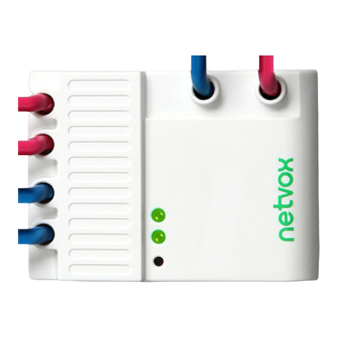
2. Product Appearance

3
3. Specification
Fully compatible with IEEE 802.15.4
Use the 2.4GHz ISM band for a total of 16 channels
100~240VAC 50/60HZ power supply
Communication distance up to 150 meters (depending on specific environmental conditions)
Simple operation and setting
Controlled circuit voltage, current, power and other parameters can be measured
4. Setting up Z805A
4-1. Power On
Connect the Z-805A to the power supply of the AC 100 to 240 V to power on the device. After the power is on, the
indicator light is flashes once. The external switch of the device can be connected to the common wall switch and
installed into 86 boxes.
Note: The internal system circuit of Z-805A product is designed in non-isolated mode. The system circuit is
connected with the equipment power supply, and the external switch wire is also connected with it. It is of strong
electrical property. Therefore, when connecting the external switch, please cut off the power supply of the device
first. Also ensure the insulation and isolation of the conductive part of the external switch.
4-2. Join the ZigBee Network
After Z805A is powered on, it will search for an existing ZigBee network and send a request to join the
network automatically. While Z805A is under the coverage from a coordinator or a router whose permit-join
feature is enabled, Z805A will be permitted to join the network. Before joining into the network, the network
indicator flashes twice every certain interval, indicating a network is detected.
A. Before Z805A is joined a ZigBee network → the network indicator will keep off.
B. After Z805A has joined a ZigBee network → the network indicator will keep green.
4-3. Permit-Join
Z805A is designed to work as a router. To allow other devices to join the ZigBee network, users could enable
the Permit-Join feature using the tips:
A. Press the Binding Key to enable the Permit-Join feature. The network indicator will flash green per
second.
B. The default Permit-Join period of time is 60 seconds.
Z805A allows up to 14 End Devices to join its network.

4
4-4. End Device Bind
Objects tio be bound: The device with On/Off cluster on the client side, such as the Z501 of NETVOX, or the
device with the meter cluster on the client side.
(B) Binding operation:
B-1. Press and hold the Binding Key for 3 seconds to send the binding request. The Network Indicator will flash
green once.
B-2 Operate the device to be bound to send binding request (refer to the user manual of the bound device)
B-3. The Network Indicator flashes green 5 times after the binding is completed; otherwise, it will flash green for
10 times.
B-4 .To unbind the device, re-execute above operations to manually unbind.
Note: It supports 16 Binding tables, 16 Group tables and 16 Scenes tables.
4-5. Control
A. Remote Control
When the device receives “on” signal to break over relay; relay magnets connects to switch, as a
result, the external circuit is turned on. When receiving “off” signal, the relay off, magnet will not
connect to switch, the switch is off, so that the external circuit is disconnected.
B. Switch Control
The switch on the external circuit can be controlled by the switch on the Z-805A, or the switch of the external
circuit can be controlled by the external switch of the Z-805A.
4-6. Current / Voltage / Power / Energy Detection.
After the load is connected to the AC output of the Z-805A, the Z-805A device can detect the voltage value
supplied to the device and the current value consumed by the load, the power of the load, and the accumulated
energy value. The Z-805A device periodically reports current, voltage, and power data to the bonded device. The
user can view the detected current and voltage value power energy value through APP.
4-7. Reset Power Consumption Summation
To reset the power consumption data, please follow the steps:
(1) Press and hold the Binding Key for 20 seconds. The Network Indicator will flash 5 times (on 3rd, 6th ,10th,
15th, and 20th second).
(2) After releasing the Binding Key, press On Key or Off Key within 3 seconds. The reset is completed.
4-8. Restore to Factory Setting
To restore it to factory setting, please follow the steps:

5
Step1. Press and hold the Binding Key for 15 seconds. The network indicator will flash green 3 times (at the 3rd,
the 10th, and the 15th second).
Step2. After releasing the Binding Key, press the Switch Key within 2 seconds. The network indicator will rapidly
flash green.
Step3. After fast flashes, Z805A will reboot, and the restore is completed.
5. Home Automation Clusters for Z805A
1.End Point(s):0x0A:
2.Device ID:Mains Power Outlet (0009)
3.The Cluster ID which EndPoin supports
Cluster ID for Z-805A
Server side Client side
EP 0X0A (Device ID: Mains Power Outlet (0009) )
Basic(0x0000) None
Group(0x0004)
Identify(0x0003)
Scene(0x0005)
On/Off(0x0006)
Commission(0x0015)
Diagnostics(0x0B05)
Meter(0x0702)
Electrical Measurement (0x0B04)
4. Related attribute definitions for each Cluster:
(1) Attributes of the Basic Device Information attribute set
Identifier Name Type Range Access Default Mandatory
/ Optional
0x0000 ZCLVersion 8-bit
Unsigned
integer
0x00 –0xff Read
only
0x03 M
0x0001 ApplicationVersion 8-bit
Unsigned
integer
0x00 –0xff Read
only
0x21 O
0x0002 StackVersion 8-bit
Unsigned
integer
0x00 –0xff Read
only
0x35 O

6
Identifier Name Type Range Access Default Mandatory
/ Optional
0x0003 HWVersion 8-bit
Unsigned
integer
0x00 –0xff Read
only
0x0A O
0x0004 ManufacturerName Character
string
0 – 32
Bytes
Read
only
netvox O
0x0005 ModelIdentifier Character
string
0 – 32bytes Read
only
Z-805AE3
R
O
0x0006 DateCode Character
string
0 – 16 bytes Read
only
20180918 O
0x0007 PowerSource 8-bit
Enumeration
0x00 –0xff Read
only
0x01 M
Attributes of the device configuration attribute set
Identifier Name Type Range Access Default Mandatory
/ Optional
0x0010 LocationDescription Character
string
0 – 16bytes Read/write Empty
string
O
0x0011 PhysicalEnvironment 8-bit
Enumeration
0x00 –0xff Read/write 0x00 O
0x0012 DeviceEnabled Boolean 0x00–0x01 Read/write 0x01 O
Product Attributes and Custom Instructions
1. The Cluster used by the Z825K233 refers to the Cluster ID (0x0702) and Electrical Measurement ClusterID
(0x0B04) used by the Simple Metering in the SE. In the Cluster ID (0x0702), Netvox customizes the current,
voltage, power, and energy attributes.
Cluster ID (0x0B04):
(1) The current attribute uses the Attribute ID: 0x0508, voltage attribute 0x0505.
(2) The power attribute uses the Attribute ID: 0x050B, and the power factor attribute 0x0510.
Cluster ID (0x0702):
(1) The custom current attribute uses the Attribute ID: 0xE000, and the custom voltage attribute 0xE001.
(2) The custom power attribute uses the Attribute ID: 0xE002, and the custom power attribute 0xE003.
(3) The attribute CurrentSummationDeliver whose attribute ID is 0x0000 corresponds to the electric energy
attribute 0xE003.
(4) 1) The power ATTRID = 0xE003 (or 0x0000), the unit is wh; the power ATTRID = 0xE002, the unit is w;
Current ATTRID = 0xE000 in mA; voltage ATTRID = 0xE001 in V

7
Custom instruction
The command to erase the current battery information is: 0xE0. The instruction format is:
Bits:8 16 8 8 8
Frame
control
Manufacturer
code
Transaction
Sequence
number
Command
identifer
Frame payload
Action
0x05 0x109F 0xe0 0x00
(clusterid:0x0702,Action:0x00)
6. Loading property
Rated Load
(AC)
**
Remark**
Max. Load
with LEDs
**Remark**
Max. Inductive
Load
(cosφ=0.4)
Max. Load
with Electric
Motors
Overload
Protection
with Auto
Power Cutoff
16A/250V 400W/8
LEDs
8A/250V 1.5HP/250V Yes
7. Related Netvox Devices
Z810B: Switch control unit with consumption display
ZB02C: Switch

8
8. Related Netvox Devices
This product does not have a waterproof function. Please place it indoors.
Note:
1. When the detected current exceeds the measurement range (16A), the device will automatically disconnect the
load within 2 seconds after the detection. At the same time, check whether the Bit1 (Current OverLoad) bit of the
attribute ACAlarmsMask is 1, and if it is 1, it will issue a broadcast Alarm, and if it is 0, it will not issue a
broadcast alarm. Alarm broadcast alarm, AlarmCluster = 0x0B04, AlarmCode = 0xF0; network indicator (red
indicator if red indicator) flashes 10 times (10, 250, 250).
2. The energy data of Z-805A is saved once every 30s if the memory chip is AT2401, once every 10s for AT2402,
and the high-capacity storage such as AT2404/08 is saved once every 1s, so the data within 30/10/1 seconds will be
lost due to power loss.
9. Important Maintenance Instructions
Your device is a product of superior design and craftsmanship and should be used with care. The
following suggestions will help you use the warranty service effectively.
• Keep the equipment dry. Rain, moisture, and various liquids or moisture may contain minerals
that can corrode electronic circuits. In case the device is wet, please dry it completely.
• Do not use or store in dusty or dirty areas. This can damage its detachable parts and electronic
components.
• Do not store in excessive heat. High temperatures can shorten the life of electronic devices,
destroy batteries, and deform or melt some plastic parts.
• Do not store in excessive cold place. Otherwise, when the temperature rises to normal
temperature,
moisture will form inside, which will destroy the board.
• Do not throw, knock or shake the device. Rough handling of equipment can destroy internal
circuit boards and delicate structures.
• Do not wash with strong chemicals, detergents or strong detergents.
• Do not apply with paint. Smudges can block debris in detachable parts and affect normal
operation.
• Do not throw the battery into a fire to prevent the battery from exploding. Damaged batteries
may also explode.
All of the above suggestions apply equally to your device, battery and accessories. If any device is
not working properly.
Please take it to the nearest authorized service facility for repair.
Table of contents
Other netvox Control Unit manuals
