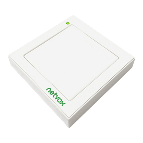
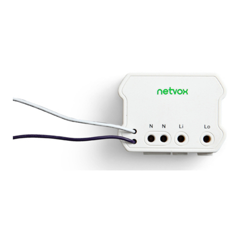
netvox Z806 User manual

Model: Z806
Wireless Switch Control Unit
Wireless Switch Control Unit
(2-Output)
User Manual
Firmware: V5.2
Hardware: V7.1

1
Content
1. Introduction...................................................................................................................................................................... 2
2. Appearance....................................................................................................................................................................... 2
3. Main Features................................................................................................................................................................... 3
4. Installation........................................................................................................................................................................ 3
4.1 Join into ZigBee network............................................................................................................................................. 4
4.2 Permit join....................................................................................................................................................................5
4.3 Binding......................................................................................................................................................................... 5
4.4 Control......................................................................................................................................................................... 5
4.5 Restore to factory setting............................................................................................................................................. 6
4.6 ZigBee description....................................................................................................................................................... 6
5. Related products:............................................................................................................................................................. 7
6. Important Maintenance Instructions............................................................................................................................. 8

2
1. Introduction
Z806 is defined as a wireless switch device based on ZigBee protocol. It has two circuits to be on or off wirelessly
controlled. It allows user using a ZigBee remote controller to wirelessly switch on or off the load attached to it.
Z806 is a router device in the network which permits other devices to join the network.
Z806 utilizes 2.4 GHz ISM band for ZigBee HA or SE profile and communicates with routers, coordinator, and end
devices in a network.
2. Appearance
External output 2
External output 1
220V AC Input
Status indicator
Network indicator
Binding key

3
3. Main Features
Device type: On/Off Output (HA Profile) / Load Control Device (SE Profile)
ZigBee high power output switch
Protocol based on ZigBee
Equipped with router device
Two dry-contact output relay controlling individual device
Compact size that can be installed in power junction box
4. Installation
Main PCB board
Relay
Relay
3
4
5
6
1
2
status led
net led
Bind key
Wireless Module
(MCU&RF
Transceiver)
Channel 1
Channel 2
ACIN
Fig 1. Z806 structure diagram

4
Fig 2. Z806 Wiring Diagram
Input power port:
Refer to Fig. 1, mark 1 and 2 are input power ports which can support input power range from AC
100V-240V
50/60HZ
Output power port:
Main PCB Board carries 2 relays that the control terminal and the controlled terminal is electrically
isolated.
Reference numeral 3,4,5,6 four terminals are output port interface of relays. Numeral 3,4 port to
connect one relay output switches at both ends. Two terminals are turned on and off by controlling
the relay inside the machine. And they are galvanically isolated from other parts of the lines on the
board (ie, here are dry contact outputs).
Numeral 5,6 port interfaces to connect one relay output switches at both ends. Two terminals are
turned on and off by controlling the relay inside the machine. And they are galvanically isolated
from other parts of the lines on the board (ie, here are dry contact outputs).
4.1 Join into ZigBee network
In order to communicate in ZigBee network, join Z806 into the network as below steps:
①Power on Z806, it will search network automatically.
②If there are coordinator or router sharing same channel in the network and allowing other
devices to join. Z806 will join the network automatically.
③After joining into ZigBee network successfully, the network indicator will stay on. Otherwise,
the network will stay off.

5
4.2 Permit join
Z806 acts as a router and allows other devices to join the network. Turn on permit join function:
press shortly binding key, status indicator flashes to show permitting join. Other devices are allowed
to join network through Z806, permitting interval 60 seconds; the network indicator will flash 60
times. Z806 will shut down permitting function after 60 seconds and the status indicator stops
flashing.
4.3 Binding
Z806 can bind with devices of client side carrying On/Off (0x0006) Cluster ID. Z806 can
receive on/off command and perform the corresponding on/off switching
Binding operation are as below:
Objects can be bound : switching devices as Z501, Z503, ZB02C, etc.
Binding operations: press and hold binding key for 3 seconds, after the status indicator flashes once,
release the key bindings, within 5 seconds press binding key N times to choose Nth channel to be
bound. Each time you press the key; the status light flashes once to show prompted key is valid. For
example , channel 2 to bind with other devices, press and hold binding key for 3 seconds, then the
status indicator blinks once, release binding key. Within 5 seconds continuously press the binding
key 2 times, the status light flashes twice individually to show each prompted key is valid . 5
seconds later, Z806 will send a binding request. Operate devices to be bound to also send a binding
request. After binding is successful, Z806 status indicator blinks 5 times. Status indicator will flash
10 times to show that binding is not successful.
NOTE: The device supports 32 groups , 32 scenes.
4.4 Control
Devices which are bound with Z806 can send on/off command to Z06.
When Z806 receives the ON command, relay magnet of the corresponding channel will connect;
thereby the external circuit of that channel is turned on. When Z806 receives OFF command, relay
magnet will disconnect, so the external circuit cut off.

6
4.5 Restore to factory setting
Z806 carries functions of saving data such as saving the distributed network addresses. If users
would like Z802 to join a new network, Z802 has to be restored to factory setting first.
To restore to factory setting, press and hold binding key for 15 seconds till status indicator flashes three time
individually at 3rd, 10th, 15th second, and then press shortly within 2 seconds; the status indicator will keep flash to
that show restoring is completed.Two indicator will then shut off; status indicator will start to search network and
Z806 will re-join the network.
4.6 ZigBee description
1.End Point(s):0x01、0x02
2.Device ID:On/Off Output (0002)
3.Cluster ID which EndPoint supports
Cluster ID for Z806
Server side Client side
EP 0X01、0x02(Device ID: On/Off Output (0002))
Basic(0x0000) None
Identify(0x0003)
Group(0x0004)
Scene(0x0005)
On/Off(0x0006)
Commissiong (0x0015)
Diagnostics(0x0B05)
(1)Attributes of the Basic Information
Identifier Name Type Range Access Default Mandatory
/ Optional
0x0000 ZCLVersion Unsigned
8-bit integer
0x00 –
0xff
Read only 0X03 M
0x0001 ApplicationVersion Unsigned
8-bit integer
0x00 –
0xff
Read only 0X34 O
0x0002 StackVersion Unsigned
8-bit integer
0x00 –
0xff
Read only 0X35 O
0x0003 HWVersion Unsigned 0x00 – Read only 0X47 O

7
8-bit integer 0xff
0x0004 ManufacturerName Character
string
0 – 32
bytes
Read only netvox O
0x0005 ModelIdentifier Character
string
0 – 32
bytes
Read only Z806E3R O
0x0006 DateCode Character
string
0 – 16
bytes
Read only 20150508 O
0x0007 PowerSource 8-bit
Enumeration
0x00 –
0xff
Read only 0X01 M
0x0010 LocationDescription Character
string
0 – 16
bytes
Read/write - O
0x0011 PhysicalEnvironment 8-bit
Enumeration
0x00 –
0xff
Read/write 0x00 O
0x0012 DeviceEnabled Boolean 0x00 –
0x01
Read/write 0x01 M
5. Related products:
Switch(model:ZB02A/B/C)
Remotes(model:Z503/Z501B)
Motion Detector(model:ZB01B)

8
6. Important Maintenance Instructions
Please keep the device in a dry place. Precipitation, humidity, and all types of liquids or moisture can contain
minerals that corrode electronic circuits. In cases of accidental liquid spills to a device, please leave the device
dry properly before storing or using.
Do not use or store the device in dusty or dirty areas.
Do not use or store the device in extremely hot temperatures. High temperatures may damage the device or
battery.
Do not use or store the device in extremely cold temperatures. When the device warms to its normal
temperature, moisture can form inside the device and damage the device or battery.
Do not drop, knock, or shake the device. Rough handling would break it.
Do not use strong chemicals or washing to clean the device.
Do not paint the device. Paint would cause improper operation.
Handle your device, battery, and accessories with care. The suggestions above help you keep your device
operational. For damaged device, please contact the authorized service center in your area.
Table of contents
Other netvox Control Unit manuals
Popular Control Unit manuals by other brands
Velocity
Velocity VL-SLC installation instructions

Bosch
Bosch GCY 30-4 Professional Original instructions
Bray
Bray TRI LOK Series Installation, operation and maintenance manual
Lenze
Lenze E94AZHY0025 Mounting instructions
Pepperl+Fuchs
Pepperl+Fuchs WCS-EIG410 manual
rako
rako RLED Series Installation, Programming and Operating Instructions
