Neutronics 4100 User manual

High Purity Instruments
MODEL 4100
OXYGEN ANALYZER
INSTALLATION MANUAL
MEASUREMENT
RANGE MODE
RUN FAULT ALM 1 ALM 2
20.9
OXYGEN
MODEL 4100 O2Analyzer
NTRON
PERCENT
PPM
PPB
File Name: MN-A-0075
Manual Part Number: C5-06-4900-05-0
Revision Level: B Date: 5/13/08
ECO: 8451
Engineered Solutions for Gas Detection and Analysi
s


Page 3
Table of Contents
TABLE OF CONTENTS 3
FORYOURSAFETY 4
CHAPTER1-INTRODUCTION 6
CHAPTER 2 – INSTALLATION INSTRUCTIONS 8
STEP 1 – ANALYZER AND RSM INSTALLATION 8
STEP 2 – ELECTRICAL CONNECTIONS 11
CHAPTER 3 – OPERATING INSTRUCTIONS 16
A.FIRSTTIMEPOWERUP 16
B. NORMAL POWER UP AND POWER DOWN 20
C. OXYGEN ALARM LEVEL SETTINGS 20
D.FEATURES 20
CHAPTER 4 – MAINTENANCE AND TROUBLESHOOTING 28
CHAPTER 5 – SPECIFICATIONS 30
WARRANTY STATEMENT AND STATEMENT OF INTENDED USE 32
APPENDIX A – AMBIENT AIR CALIBRATION 33
APPENDIXB–SYSTEMFAULTS 35
APPENDIX C – OXYGEN ALARM LEVEL SETTINGS 38
APPENDIXD–RS-232PORT 39
APPENDIXE-SYSTEMSETUP 40
APPENDIX F – SPARE PARTS LIST 43
APPENDIX G – MATERIAL SAFETY DATA SHEET 44

Page 4
For Your Safety:
PLEASE READ THIS MANUAL IN ITS ENTIRETY BEFORE ATTEMPTING
INSTALLATION OR OPERATION! Attempting to operate the Model 4100 without
fully understanding its features and functions may result in unsafe conditions.
•Never expose the Model 4100 analyzer chassis to water, high humidity or moisture. The analyzer
chassis is not watertight.
•Never expose the Model 4100 to flame or high temperatures.
•Never expose the Model 4100 analyzer to flammable gases or vapors. The unit is not rated Explosion
Proof or Intrinsically Safe.
•Ensure the analyzer unit is mounted in an area of free airflow to prevent the chassis from exceeding
the operating temperature specifications. Do not mount the analyzer against hot surfaces. Do not
block the ventilation louver on the analyzer chassis.

Page 5
Thank you for purchasing the Model 4100 Analyzer for your
PPB/PPM/% range Oxygen measurement.
The Model 4100 Compact Analyzer is a user friendly, microprocessor controlled analyzer designed to be used
with either the 4-LP-N1-SS or the 4-SPM-N1-SS remote sensor module for oxygen measurements in inert gas
backgrounds. It has many features to offer the user, which will be described in this manual. We require that
all personnel who use the instrument read this manual to become more familiar with its proper operation.
For further detail regarding the maintenance and in-field service of the Model 4100 analyzer, please contact
the Neutronics Inc. Customer Service Department. If you have questions or comments, we would like to hear
from you.
Neutronics Inc. Customer Service Department
456 Creamery Way
Exton, PA 19341
Tel: (610) 524-8800
Toll Free: (800) 378-2287 (US only)
Fax: (610) 524-8807
Visit us at www.neutronicsinc.com
Equipment Serial Number: ________________
(For faster service, please have this number ready if for any reason you need to contact us about your instrument)
Copyright ©2008 Neutronics Inc.
This work is protected under Title 17 of the US Code and is the sole property of Neutronics Inc. No part of this document may be
copied or otherwise reproduced, or stored in any electronic information retrieval system, except as specifically permitted under
US copyright law, without the prior written consent of Neutronics Inc.
1CHAPTER 1–INTRODUCTION

Page 6
The Model 4100 is a microprocessor-based instrument that indicates the measured oxygen
concentration in either parts-per-billion, parts-per-million, or percent by volume when used with a
Neutronics remote sensor module.
The Model 4100 analyzer is designed to be flush mounted to a panel or console. Because of its small size,
the analyzer can be integrated into a variety of equipment or control panels. Some of the analyzer
features include:
•Large 4-Digit 7-Segment LED display for oxygen readout and system configuration.
•Front panel keypads for user setup access and calibration.
•Two oxygen alarms relays with configurable outputs for process control use.
•One System Fault relay output.
•4-20 mA Analog Current Output, range configurable.
•0-1/5/10 VDC Analog Voltage Output, range configurable.
•0-10V Range Identification Voltage to be used with the Analog Outputs.
•RS-232 Serial Interface Port.
Page 7
Introduction (continued)
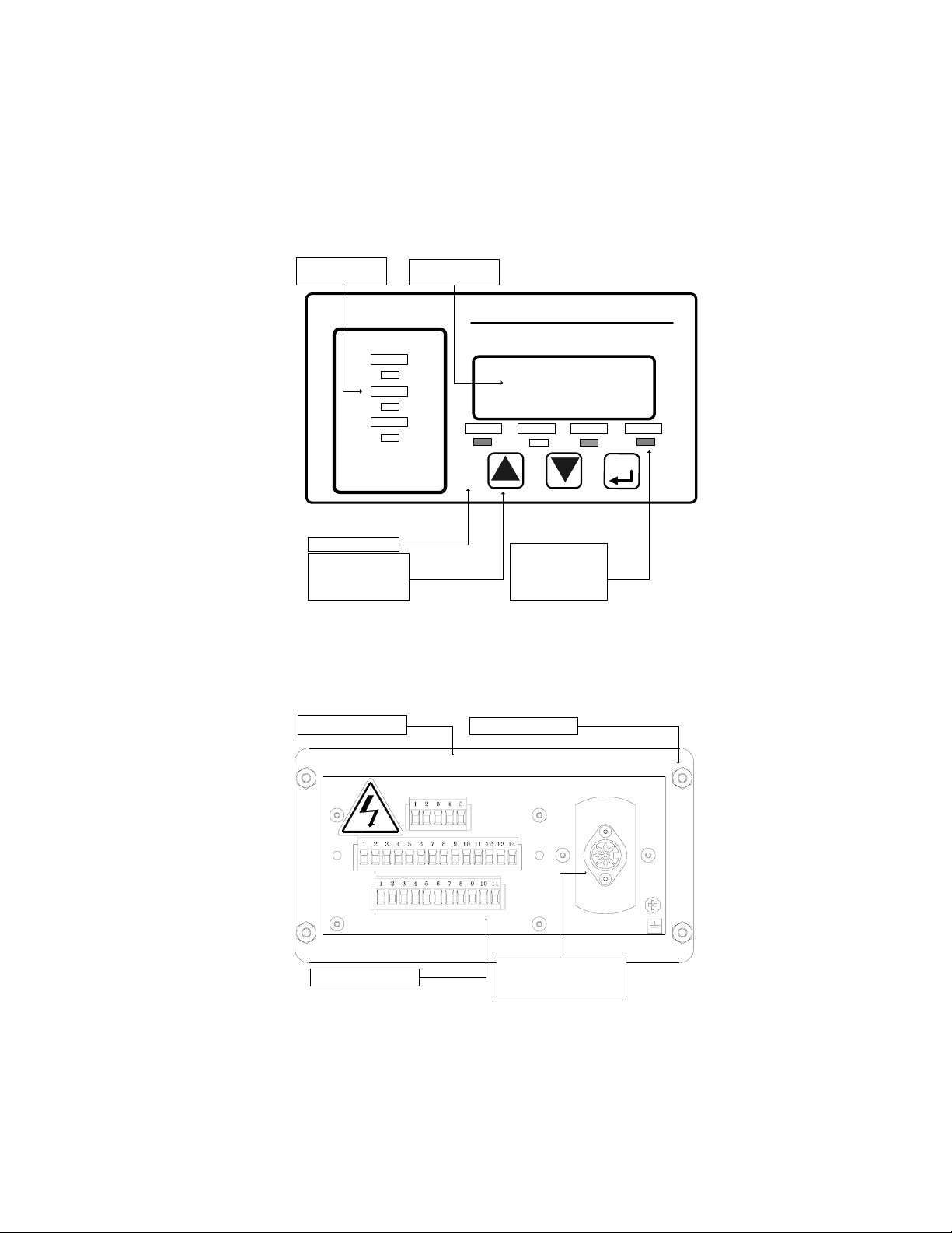
Front View
NEMA 4 Panel Mounting
Gasket Mounting Studs
Removable Terminal Blocks
Interface Port for the Sensor
Interface Cable to the Remote
Sensor
Module
Rear View
Figure 1 – Model 4100 Analyzer Front And Rear View
M
EASUREMENT
R
ANGE
MODE
RUN FAULT ALM 1 ALM 2
20.9
O
XYGEN
MODEL 4100 O
2
Analyzer
N
TRON
PERCENT
PPM
PPB
Measurement Range
Indicator
LED Bank
NEMA 4 Front Panel
Large, Menu-Driven Push-
Button Operators For:
Increment
Decrement
Mode Select
Color Coded Status
Indicators:
RUN = Green
FAULT = Yellow
ALARM 1 = Red
ALARM 2 = Red
Oversized LED Displays
Page 8
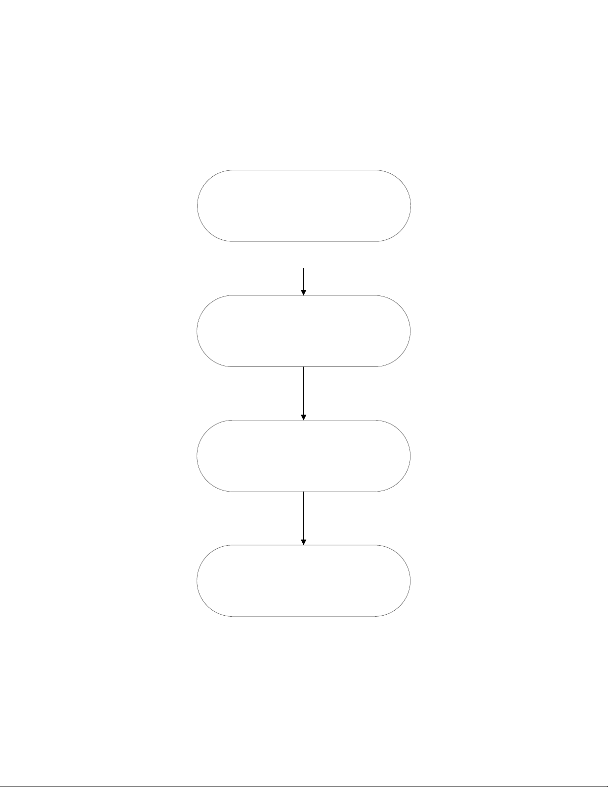
2CHAPTER 2–INSTALLATION INSTRUCTIONS
STEP 1:
ANALYZER/RSM
INSTALLATION
STEP 2:
ELECTRICAL CONNECTIONS
STEP 3:
POWER UP
STEP 4:
AIR VERIFICATION/CALIBRATION
Fi
g
ure 2
–
Power U
p
Se
q
uence

Page 9
Step 1 Analyzer and RSM Installation
Install either the 4-LP-N1-SS or the 4-SPM-N1-SS remote sensor module as detailed by its installation
manual.
WARNING: The internal components of the Model 4100 analyzer are fragile. Do not drop
the analyzer during installation. Do not expose the unit to shock or vibration during
installation. Failure to comply may damage the fragile components inside the analyzer and
may result in loss of warranty.
CAUTION: The Model 4100 analyzer and its remote sensor module are shipped as a matched set. If
installing more than one system, verify that the serial numbers on the analyzer and the remote sensor
module match. Failure to comply may result in reduced measurement accuracy.
Observe the following guidelines when installing the Model 4100 Analyzer.
•Locate the analyzer so that the range and status LEDs, and 7-segment LED readout can be easily
read.
•Locate the analyzer so that the interface buttons on the display panel can be easily accessed.
•Allow ample space at the rear of the analyzer for easy access to all electrical connections.
•Be sure that the analyzer will not be exposed to water, adverse temperature, or shock.
•Be sure that the analyzer has free air flow around the vent slots on the chassis to prevent
overheating.
Cut/drill the mounting panel. Cut panel as shown in Figure 3. Drill four clearance holes for the #8-32
threaded mounting studs. Trim all burrs or sharp edges in the cutout or mounting-holes. Hex nuts and
lock washers are included for securing the unit to a panel.

Page 10
Step 1 Analyzer and RSM Installation (continued)
Slide the analyzer unit into the cutout. Slide the rear-chassis first. Seat the control panel gasket on
the mounting surface. The gasket on the analyzer control panel ensures a watertight seal around the
control panel cutout. Secure the threaded mounting studs with the supplied hex-nuts, and internal-
tooth lock-washers. The front of analyzer is suitable for NEMA Type 4, IP20 environments when
properly installed. The rear electronics chassis is suitable for NEMA Type 1, IP 20 environments.
PANEL CUTOUT & DRILL PATTERN
4 PLACES
6.62" 16.81cm
6.20" 15.50cm
2.75"
6.99cm
2.91"
7.39cm
.189 DIA. HOLE (.429cm)
Fi
g
ure 3 – Anal
y
zer Panel Cutout Dia
g
ram
Page 11
Step 2 – Electrical Connections
CAUTION: Be sure all mains power supply is off before attempting the electrical
connections to the analyzer and remote sensor module. DO NOT WORK WITH LIVE WIRES!
Do not leave any exposed wire at the connectors or cables.
DANGER: Electrical connections on the rear of the analyzer may have hazardous voltages present
once power has been applied to the unit. High voltages may remain present for a short time even after
power has been disconnected. All standard electrical safety precautions must be undertaken when
making electrical connections to the remote sensor module.
DANGER: The Model 4100 analyzer is not rated intrinsically safe or explosion proof. Be certain that
no flammable gases are present in the area.
CAUTION: The Model 4100 rear housing is not rated waterproof. Do not mount the analyzer or the
sensor in an area where it may contact water or other liquid elements.
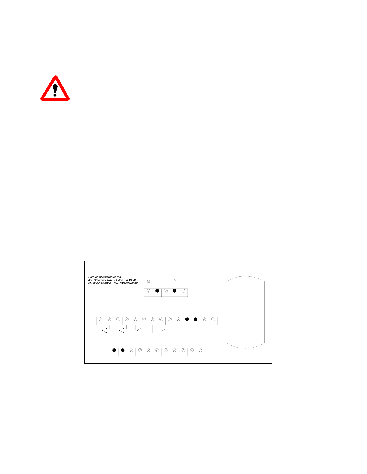
All electrical connections to the Model 4100 Analyzer is to be made to the three terminal blocks and the
sensor interface socket located at the back of the analyzer chassis. A label depicting the terminal block
arrangement is affixed to the top of the chassis as reference. The terminal blocks may be removed for
wiring.
*
12
SERVICE PORT
RS-232
ALARM 1ALARM 2FAULTTEMP
TB3 1
*
321
TB2
CNOC
ANALOG
4
12V DC
3256
-
BAT. BU
+
*
V-OUT
+-
78910
I-OUT
+-TXRX
7654
NO C NC NO
111098
NONCC*
PROCESS ANALYZER DIVISION
TRON
N
90-264 VAC, 47-63 Hz, 20 VA
TB1 12
GND *
34
AC-N *
5
AC-L
AC POWER INPUT
V-OUT
NO CONNECTION
11
*
RTN
1413
+- CONNECTIONS
SENSOR
SEE MANUAL FOR
RANGE
Fi
g
ure 4
–
Electrical Connections Label

Page 12
Step 2 – Electrical Connections (continued)
Figure 5 – Analyzer chassis electrical connections (continued).
123
TB2 4 5 6 7 8 9 10 11 12 13 14
Failsafe
Fault
CNO CNCNO
Oxygen
Alarm 2
CNC
NO +-
1 2 3
TB3 45678910 11
Bat.
BU
+-
V
Out
+-
mA
Out
+-
RS-232
TX RX RTN
12
VDC
no
connection
no
connection
Service
Port
NO = Normally Open
NC = Normally Closed
C = Common
VAC POWER INPUT,
90-264 VAC, 47-63 Hz
13
TB1 5
24
GND AC-N AC-L
CNO
Temp
OK Oxygen
Alarm 1 Range ID
Voltage

Page 13
Step 2 – Electrical Connections (continued)
The following is a list of all possible electrical connections to the Model 4100 analyzer
Oxygen Alarm-1 Relay Output
Relay Type: Form 1 C, SPDT, 5A @ 250 VAC, 5A @ 30VDC
Connections: Common: Terminal Block TB2 Pin 8
Normally Closed Output: Terminal Block TB2 Pin 9
Normally Open Output: Terminal Block TB2 Pin 10
Oxygen Alarm-2 Relay Output
Relay Type: Form 1 C, SPDT, 5A @ 250 VAC, 5A @ 30VDC
Connections: Common: Terminal Block TB2 Pin 5
Normally Closed Output: Terminal Block TB2 Pin 6
Normally Open Output: Terminal Block TB2 Pin 7
System Fault Relay Output
Relay Type: Form 1 B, SPST, 5A @ 250 VAC, 5A @ 30VDC
Connections: Common: Terminal Block TB2 Pin 3
Normally Open Output: Terminal Block TB2 Pin 4
Temperature OK Relay Output
Relay Type: Form 1 B, SPST, 5A @ 250 VAC, 5A @ 30VDC
Connections: Common: Terminal Block TB2 Pin 1
Normally Open Output: Terminal Block TB2 Pin 2
Range ID Output
Use the Range ID voltage with either the analog voltage or the analog current output to identify
the full span oxygen concentration measurement. Use 20-AWG, 2-conductor, stranded-wire,
twisted pairs for the connections.
Output Voltage: 0 - 10 Volts DC
Connections: Voltage + Output: Terminal Block TB2 Pin 13
Voltage - Output: Terminal Block TB2 Pin 14
Analog Voltage Output
The analog voltage output is factory pre-set to be either 0-1, 0-5, or 0-10 volts. Use 20-AWG, 2-
conductor, stranded-wire, twisted pairs for the connections.
Output Voltage: 0 – 1, 0 – 5, or 0 - 10 Volts DC
Connections: Voltage + Output: Terminal Block TB3 Pin 5
Voltage - Output: Terminal Block TB3 Pin 6

Page 14
Step 2 – Electrical Connections (continued)
Analog Current Output
The analog current output is a negative ground, non-isolated 4-20 mA current loop. Use 20-
AWG, 2-conductor, stranded-wire, twisted pairs for the connections.
Output Voltage: 4 – 20 mA
Maximum Loading: 250 ohms
Connections: Current + Output: Terminal Block TB3 Pin 7
Current - Output: Terminal Block TB3 Pin 8
Battery Backup (Optional)
These terminals may be used to connect the Model 4100 analyzer to a 12V battery backup system
such as a lead acid battery. Battery backup function is not required for normal operations.
Input Voltage: 12 volts nominal
Connections: Battery + Terminal: Terminal Block TB3 Pin 3
Battery - Terminal: Terminal Block TB3 Pin 4
RS-232 Service Port
For interfacing with any standard PC computer via serial port, use 20-AWG, 3-conductor,
shielded, stranded-wire, jacketed cable, terminated on one end with a female DB9 connector. The
shielding should be drained to DC ground at the computer. Use ferrite core is to minimize RFI
interference if necessary. Install the ferrite core within 6 inches of the analyzer service port. Loop
the serial cable around the ferrite core once (the serial cable will pass through the ferrite core
twice). (See Figure 6).
SIGNAL
DESIGNATION AT
ANALYZER
ANALYZER TB2
CONNECTION
SIGNAL
DESIGNATION AT
COMPUTER
COMPUTER DB9
SERIAL PORT
CONNECTION
TX Pin 9 RX Pin 2
RX Pin 10 TX Pin 3
RTN Pin 11 RTN Pin 5

Page 15
Step 2 – Electrical Connections (continued)
Mains Power
Use minimum 16-AWG, 3-conductor, stranded-wire for mains power connections.
Mains Power Voltage: 90-264 Volts AC, 47 – 63 Hz, Single Phase
Connections: AC-Line: Terminal Block TB3 Pin 3
AC-Return: Terminal Block TB3 Pin 3
AC-Ground:Terminal Block TB3 Pin 3
WARNING: Do not apply mains power to the analyzer or the remote sensor module
until all the electrical connections to the analyzer and the remote sensor module, and all the
pneumatic connections to the remote sensor module have been properly installed.
Remote Sensor Module Interface Cable
Use the remote sensor module interface cable as supplied. Connect to the socket located to the rear
of the Model 4100 analyzer. See figure 1 for the location of the socket
Serial Cable
Ferrite Core
Cable Tie
Cable Tie
Figure 6
–
RS-232 Ferrite Core

Page 16
3CHAPTER 3–OPERATING INSTRUCTIONS
A. First Time Power Up
The Model 4100 is shipped ready to use, right from the carton. Its default configuration has been set to
your application. Review the default configuration settings, as shown in the analyzer software setup log
sheet, shipped with your Model 4100 analyzer. Before commissioning your system, ensure that the
default settings match your application. Contact the factory if your default settings do not match your
application.
WARNING: Verify that the Model 4100 analyzer remote sensor module heater voltage
has been properly configured to your mains power voltage: 115 or 230 VAC. Although the
analyzer can operate at any voltage between 90 and 264 VAC, it requires that the heater
voltage be correctly set to properly regulate the sensor heater temperature inside the
remote sensor module. If the heater voltage setting does not match the mains power voltage, the
remote sensor module may be permanently damaged. Failure to comply may result in loss of warranty.
WARNING: Do not apply mains power to the analyzer or the remote sensor module
until all the electrical connections to the analyzer and the remote sensor module, and all
the pneumatic connections to the remote sensor module have been properly installed.

Page 17
First Time Power Up (continued)
FIRST TIME POWER UP CHECK LIST
Have you:
Verified that all the electrical and pneumatic connections to the remote sensor module have been
properly installed?
Verified that all the electrical connections to the analyzer have been properly installed?
Verified that the analyzer is properly connected to the remote sensor module via the sensor
interface cable?
Ensured that none of the mains power wiring to both the analyzer and the remote sensor module
are exposed?
Verified that the 4100 heater voltage setting matches the mains power voltage?
Mounted the analyzer in areas where there are no flammable vapors?
Mounted the analyzer away from exposure to rain, dripping water, or hose down?
Read this manual in its entirety?
Read the remote sensor module manual in its entirety?
First Time Power Up Instructions
1.Apply Ambient Air to the Remote Sensor Module: Apply clean, dry oil-free ambient air to the
remote sensor module. See the remote sensor module installation manual for more detail.
2.Apply Mains Power: Apply mains power to both the analyzer and the remote sensor module. The
Model 4100 analyzer will perform the following power up sequence:
a. Lamp Test (Verify): Verify that all the 7-Segment display and discrete LEDs light up and
flash. If any of the display segments or LEDs do not light up, remove all mains power and
return both the analyzer and remote sensor module to either the factory or a certified
service center for servicing.
b. Software ID (No Action): After completing the lamp test, the 7-Segment display will
show a 4-digit number signifying the software build number.

Page 18
First Time Power Up (continued)
First Time Power Up Instructions (continued)
c. Heater Voltage Setting (Verify): After indicating the software build number, the analyzer
will display either “110” or “220”. If the display shows “110” the analyzer is set up to
operate the sensor heater mains power voltage at 115 +/- 15 VAC. If the analyzer
display shows “220” the analyzer is set-up to operate at mains power voltage of 230 +/-
30 VAC. Verify that the heater voltage setting matches your mains power supply
voltage.
CAUTION: If the Model 4100 analyzer heater voltage setting does not match the mains power
voltage, power down both the analyzer and the remote sensor module immediately.
Contact the factory or an approved service center to correct the heater voltage setting.
Failure to comply may damage the remote sensor module permanently and result in loss
of warranty.
3.Wait 15 Minutes for Sensor to Warm Up to Operating Temperature: Upon completing the power
up sequence, the Model 4100 will bring up the sensor heater temperature to the operating
temperature. This process will take about 15 minutes. During this period the display will
alternate between “nr” for not ready and the sensor temperature in degrees Centigrade.
NOTE: If the Model 4100 fails to increase sensor heater to operating temperature, the display will
flash “HF” for heater failure. Power down both the analyzer and the remote sensor module. Check
the sensor interface cable connection to ensure integrity. Repeat the power up procedure. If
problem persists, return both the analyzer and the remote sensor module to the factory or a certified
service center for servicing.
4.Temperature Stabilization: After completion of the warm-up sequence, the analyzer and the
remote sensor module is ready for calibration and oxygen measurement. However, it is
recommended that the user wait for an additional 1 hour for the system to reach temperature
stabilization for the most accurate calibration and measurements.
5.Measure Air Sample (Verify): After temperature stabilization, if the Model 4100 analyzer displays
between 20.7% and 21.1% at ambient air, calibration is not necessary. Otherwise, verify that
clean, dry, oil-free ambient air is supplied to remote sensor module at the pressure and flow rate
required by the remote sensor module manual. If the sample air supply requirements to the
remote sensor module is met and the reading is not within the stated tolerance, perform air
calibration per Appendix A.
First Time Power Up (continued)
6.Verify Outputs: If the Model 4100 analyzer displays between 20.7% and 21.1% after warm-up,
and all the first time power-up verifications have been completed, Check the fault, temperature
OK, and oxygen alarm relay contacts to ensure that they are wired properly and functioning
normally. Also, check the analog current, analog voltage, and range ID voltage outputs to
ensure that they are functioning normally.

Page 19
7.Apply The Gas To Be Analyzed: Apply the gas that is to be analyzed to the remote sensor module.
Verify that the oxygen concentration display, the status LEDs, relay contact outputs, the analog
outputs and the Range ID outputs are wired properly and functioning normally.

Page 20
B. Normal Power Up and Power Down Instructions
After the instructions for the first time power up has been completed, the Model 4100 analyzer and its
remote sensor module can be run continuously. For periods when the analyzer and remote sensor
module are not in use, power both units down. Wait at least 15 minutes after power down to ensure that
the sensor is cool before reapplying power to both the analyzer and the remote sensor module again.
C. Oxygen Alarm Level Settings
If the user's process requires adjustments to either oxygen alarm level, follow adjustment procedure in
Appendix C.
D. Features
The Model 4100 is intended to be used with the remote sensor module to measure oxygen concentrations
in inert background. The Model 4100 Analyzer comes equipped with several operational features. Each
feature will be discussed in detail separately:
•Three Pushbutton Control Panel Interface.
•4-Digit 7-Segment Oxygen Concentration Display with Measurement Range LEDS.
•Four Status LEDs: RUN, FAULT, ALARM 1 and ALARM 2.
•Four relay outputs: TEMPERATURE OK, FAULT, ALARM 1 and ALARM 2.
•Three outputs: Analog Current, Analog Voltage & Range ID voltage.
•RS-232 output.
D. Features (continued)
Control Panel User Interface
The Model 4100 Analyzer has three pushbuttons labeled as “UP” “DOWN” and “MODE” on the
front panel. These pushbuttons are used for special functions like calibration and accessing the
user setup mode. See the appendices for more details on the usage of the pushbuttons. When
instructions specify pressing the "MODE" key more than once, press and release the "MODE" key
approximately once every half-second.
Table of contents
Other Neutronics Analytical Instrument manuals


