Neutronics NTRON PERCENT 5124BE-N1-WO User manual

Engineered Solutions for Gas Detection and
A
nalysis
High Purity Instruments
MODEL 5124BE-N1-WO
OXYGEN ANALYZER – PERCENT RANGE
WITH REMOTE SENSOR MODULE
INSTALLATION MANUAL
File Name: MN-A-0177
Manual Part Number: 5-06-4900-65-0
Revision Level: A Revision Date: 8/19/08
ECO: 8541
A DIVISION OF
456 Creamery Way, Exton, PA 19341
www.neutronicsinc.com


Table of Contents
TABLE OF CONTENTS...................................................................................................................3
FOR YOUR SAFETY:.......................................................................................................................4
THANK YOU FOR PURCHASING THE MODEL 5124BE-N1-WO ANALYZER FOR ZERO TO
25 % RANGE OXYGEN MEASUREMENT.........................................................................................5
1CHAPTER 1 – INTRODUCTION AND OVERVIEW .................................................6
2CHAPTER 2 – SYSTEM INSTALLATION AND START-UP ....................................8
STEP 1 – ANALYZER INSTALLATION ..................................................................................................9
STEP 2 – SENSOR INSTALLATION .....................................................................................................10
STEP 3 – ELECTRICAL INSTALLATION ..............................................................................................12
3CHAPTER 3 – OPERATING INSTRUCTION ...........................................................21
A. FIRST TIME POWER UP................................................................................................................21
B. NORMAL POWER UP AND POWER DOWN INSTRUCTIONS.............................................................23
C. OXYGEN ALARM LEVEL SETTINGS..............................................................................................23
D. FEATURES ...................................................................................................................................24
Temperature OK Relay................................................................................................................24
Fault Relay ..................................................................................................................................24
Oxygen Alarm 1 & Alarm 2 Relays .............................................................................................25
Analog Voltage & Analog Current Output..................................................................................26
Range ID Voltage ........................................................................................................................26
RS-232 Port .................................................................................................................................27
4CHAPTER 4 – MAINTENANCE AND TROUBLESHOOTING ..............................29
5CHAPTER 5 – SPECIFICATIONS ****......................................................................31
WARRANTY .....................................................................................................................................33
INTENDED USE FOR THE MODEL 5124BE-N1-WO .........................................................................34
APPENDIX A: AMBIENT AIR CALIBRATION ......................................................................................35
APPENDIX B: SYSTEM FAULTS.........................................................................................................38
APPENDIX C: OXYGEN ALARM LEVEL SETTINGS ............................................................................40
APPENDIX D: RS-232 PORT.............................................................................................................42
APPENDIX E: SYSTEM SETUP ...........................................................................................................44
APPENDIX F – SPARE PARTS LIST ....................................................................................................46
APPENDIX G – MSDS MATERIAL SAFETY DATA SHEET .................................................................47
APPENDIX H – DECLARATION OF CONFORMITY ..............................................................................48
APPENDIX I – DECOMMISSIONING THE MODEL 5124BE-N1-WO ANALYZER .................................49
Manual Part Number:
5-06-4900-65-0
Revision Level: A
ECO 8541
File Name: MN-A-0177 Page 3

For Your Safety:
PLEASE READ THIS MANUAL IN ITS ENTIRETY BEFORE ATTEMPTING
INSTALLATION OR OPERATION! Attempting to operate the
Model 5124BE-N1-WO without fully understanding its
features and functions may result in unsafe conditions.
• Always use protective eye wear and observe proper safety procedures
when working with pressurized gases.
• Always assure the pressure of gas entering the Model 5124BE-N1-WO
sensor is 1-10 psig.
• Always calibrate the Model 5124BE-N1-WO at an equivalent pressure and
flow rate to the measured gas. Maximum pressure should not exceed 10
psig.
• Always allow the Model 5124BE-N1-WO to cool down before attempting to
access the sensor.
• Never expose the Model 5124BE-N1-WO analyzer or the remote sensor
chassis to water, high humidity or moisture. The analyzer chassis is
not watertight.
• Never expose the Model 5124BE-N1-WO analyzer or the remote sensor to
flame or high temperatures.
• Never expose the Model 5124BE-N1-WO analyzer or the remote sensor to
flammable gases or vapors. The unit is not rated Explosion Proof, or
Intrinsically Safe.
• Never expose the Model 5124BE-N1-WO sensor module directly to
unregulated gas lines, cylinder gas. High gas pressures may cause the
sensor components to rupture.
• Ensure the analyzer and the remote sensor unit is mounted in an area
of free airflow to prevent the chassis from exceeding the operating
temperature specifications. Do not mount the analyzer against hot
surfaces. Do not block the ventilation louver on the analyzer
chassis.
Manual Part Number:
5-06-4900-65-0
Revision Level: A
ECO 8541
File Name: MN-A-0177 Page 4

Thank you for purchasing the Model 5124BE-N1-
WO Analyzer for zero to 25 % range Oxygen
measurement.
The Model 5124BE-N1-WO Compact Analyzer is a user friendly, microprocessor
controlled Oxygen measuring instrument. It has many features to offer the
user, which will be described in this manual. We require that all
personnel who use the instrument read this manual to become more familiar
with its proper operation.
For further detail regarding the maintenance and in-field service of the
Model 5124BE-N1-WO analyzer, please contact the Neutronics Inc. Customer
Service Department. If you have questions or comments, we would like to
hear from you.
Neutronics Inc. Customer Service Department
456 Creamery Way
Exton, PA 19341
Tel: (610) 524-8800
Toll Free: (800) 378-2287 (US only)
Fax: (610) 524-8807
Visit us at www.neutronicsinc.com
Equipment Serial Number: ________________
(For faster service, please have this number ready if for any reason you need to contact
us about your instrument)
Copyright 2008 Neutronics Inc.
This work is protected under Title 17 of the US Code and is the sole property of
Neutronics Inc. No part of this document may be copied or otherwise reproduced, or
stored in any electronic information retrieval system, except as specifically permitted
under US copyright law, without the prior written consent of Neutronics Inc.
Manual Part Number:
5-06-4900-65-0
Revision Level: A
ECO 8541
File Name: MN-A-0177 Page 5

Installation and Operations Manual
1 CHAPTER 1 – INTRODUCTION AND OVERVIEW
The Model 5124BE-N1-WO analyzer is a microprocessor-based instrument for
measuring percent level oxygen in an inert gas background.
The analyzer is based on an amperiometric zirconium oxide remote sensor.
This sensor assures reliability and fast response for oxygen
concentration measurements, in inert gas backgrounds, in the percent
range. The solid-state sensor offers long life with little maintenance.
The sensor is not affected by dry atmospheres or by extremely cold
storage temperatures. It also has a very long storage life.
The sample gas is flowed through a self-contained external sensor
housing. The pneumatic connections are made to the 3/4"-16 male
threaded port for ease of use.
The Model 5124BE-N1-WO analyzer is designed to be flush-mounted to a
panel or console. Because of its small size, the analyzer can be
integrated into a variety of equipment or control panels. Some of the
analyzer features include:
• Compact, rapid-response external Zirconia oxygen sensor module
• Two User-adjustable oxygen Alarms with configurable relay outputs for
process control use.
• One System Fault relay output.
• One Temperature OK relay output.
• 4-20 mA Analog Current Output, range configurable.
• 0-1/5/10 VDC Analog Voltage Output, range configurable.
• 0-10V Range Identification Voltage to be used with the Analog Outputs
• RS-232 Serial Interface Port.
Manual Part Number:
5-06-4900-53-0
Revision Level: A
ECO 8541
File Name: MN-A-0177 Page 6

NEMA 4 PANEL
MOUNTING GASKET MOUNTING STUDS
ELECTRICAL
CONNECTION PORT
TO REMOTE
SENSOR
REMOVABLE
TERMINAL BLOCKS
EARTH GROUND
TERMINAL
Figure 1 – Model 5124BE-N1-WO Rear View
Manual Part Number:
5-06-4900-65-0
Revision Level: A
ECO 8541
File Name: MN-A-0177 Page 7

Installation and Operations Manual
2 CHAPTER 2 – SYSTEM INSTALLATION AND START-UP
STEP 1:
ANALYZER INSTALLATION
STEP 2:
SENSOR INSTALLATION
STEP 3:
ELECTRICAL CONNECTIONS
STEP 4:
POWER UP
STEP 5:
AIR VERIFICATION/CALIBRATION
Figure 2 – Power Up Sequence
Manual Part Number:
5-06-4900-53-0
Revision Level: A
ECO 8541
File Name: MN-A-0177 Page 8
Step 1 – Analyzer Installation
WARNING: The internal components of the Model 5124BE-N1-WO
analyzer and the remote sensor are fragile. Do not drop the
analyzer or the remote sensor during installation. Do not
expose the unit to shock or vibration during installation.
Failure to comply may damage the fragile components inside the analyzer
and remote sensor may result in loss of warranty.
The Model 5124BE-N1-WO analyzer is designed to be mounted flush to the
surface of an equipment control panel. Observe the following guidelines
when installing the analyzer:
• Allow ample space at the rear of the analyzer for easy access to
all electrical and pneumatic connections.
• Be sure that the analyzer will not be exposed to water, adverse
temperature, or shock.
• Be sure that the analyzer has free air flow around the vent slots
on the chassis to prevent overheating.
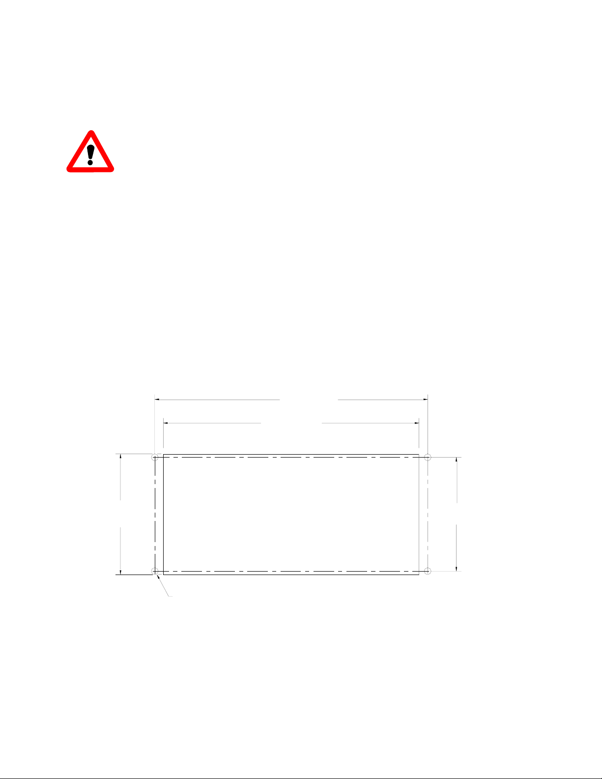
PANEL CUTOUT & DRILL PATTERN
4 PLACES
6.62" 16.81cm
6.20" 15.50cm
2.75"
6.99cm
2.91"
7.39cm
.189 DIA. HOLE (.429cm)
Figure 3 – Analyzer Panel Cutout Diagram
Manual Part Number:
5-06-4900-65-0
Revision Level: A
ECO 8541
File Name: MN-A-0177 Page 9

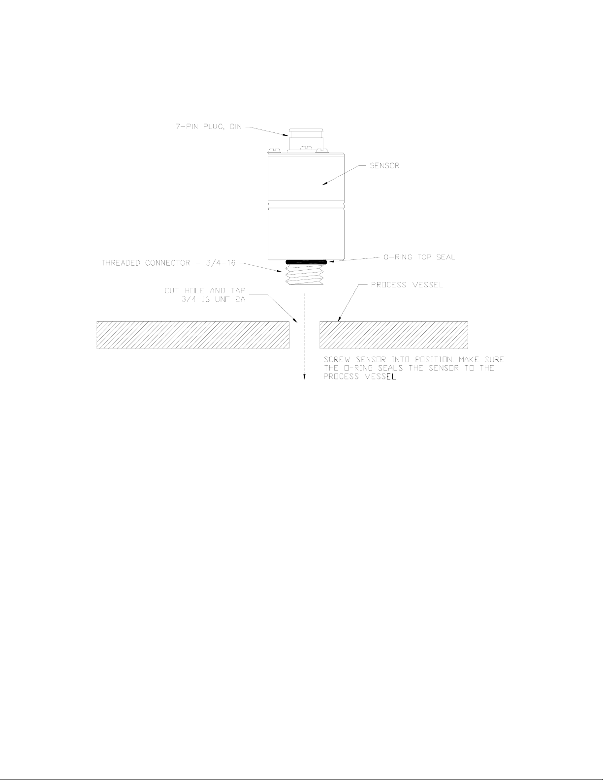
Step 2 – Sensor Installation
All pneumatic connections are to be made to the Model 5124BE-N1-WO
remote sensor. The remote sensor is designed to be screwed-on in-situ
to the process vessel at which the oxygen concentration measurements are
to be made.
Drill the Sample Port. Locate the sample point on the process vessel
at which the oxygen concentration measurements are to be taken. Drill a
hole at the location. The size of the initial drill hole should be
between 0.68” to 0.70” diameter depending on the wall thickness of the
sample process vessel.
Tap Engagement Threads to the Sample Port. Using a 3/4-16 UNF-2A
tap tool, tap the engagement threads to the sample port. If the process
vessel wall is very thick, tap to a minimum depth of 0.5” to ensure
proper engagement of the external sensor to the process vessel.
Thoroughly clean both the sample port and process vessel of any burrs,
slivers, or tap oils before installing the sensor.
Screw the Sensor to the Sample Port. Once the sample port has been
properly threaded and cleaned, screw the sensor to the sensor port.
Make sure that the O-ring at the base of the external sensor port neck
is properly compressed between the sensor body and the process chamber
ball. Failure to comply will cause the process gas to leak into the
atmosphere.
WARNING: The external sensor is designed to measure oxygen
concentrations in gas form in an inert gas background. If
there are fluids in the process vessel, select a sample
location at which the sensor will not be directly exposed to
the fluid.
WARNING: The acceptable background gases for oxygen measurements are
nitrogen and argon. Some gases will affect the accuracy of the sensor
while others may damage the sensor permanently. Contact Neutronics if
you are not sure about the affect of your process gases on the external
sensor.
WARNING: Do not over pressurize the sample inlet port as this may
permanently damage the internal components of the analyzer. Failure to
comply may void the warranty.
Manual Part Number:
5-06-4900-65-0
Revision Level: A
ECO 8541
File Name: MN-A-0177 Page 10
.
Figure 4 – Sensor mounting detail
Manual Part Number:
5-06-4900-65-0
Revision Level: A
ECO 8541
File Name: MN-A-0177 Page 11

Step 3 – Electrical Installation
CAUTION: Be sure all mains power supply is off before
attempting the electrical connections to the analyzer and
remote sensor. DO NOT WORK WITH LIVE WIRES! Do not leave any
exposed wire at the connectors or cables. Before applying
power, ensure terminal blocks are fully inserted into the mating
connector at the analyzer.
DANGER: The Model 5124BE-N1-WO analyzer and its external sensor are
not rated intrinsically safe or explosion proof. Be certain that no
flammable gases are present in the areas where the analyzer and the
external sensor will be installed.
CAUTION: The Model 5124BE-N1-WO analyzer and external housings are
not rated waterproof. Do not mount the analyzer or the sensor in an area
where it may contact water or other liquid elements.
WARNING: The Model 5124BE-N1-WO is not equipped with a circuit
breaker. A disconnecting switch or a circuit breaker must be installed
in series with the mains power to the analyzer.
All electrical connections to the Model 5124BE-N1-WO analyzer is to be
made to the three terminal blocks and sensor interface socket located at
the back of the analyzer chassis. A label depicting the terminal block
arrangement and the location of the bayonet connector is affixed to the
top of the chassis as reference. The terminal blocks may be removed for
wiring.
The electrical connection to the Model 5124BE-N1-WO external sensor is
to be made to the analyzer interface socket. Use the sensor interface
cable provided by Neutronics.
Manual Part Number:
5-06-4900-65-0
Revision Level: A
ECO 8541
File Name: MN-A-0177 Page 12

CAUTION: In order to comply with CE EN61326-1:2006
standards, all electrical connections to the three terminal
blocks on the back of the analyzer are to be made using
shielded cable conductors. Each electrical connection to the
terminal blocks must be looped through the ferrite clamp
provided. If more than one shielded cable conductor is used, the
individual wires from the different cables may share the same ferrite
clamp. Strip the cable jacket back about 8 inches to ensure all the
individual wires fit through the ferrite clamp. Additional ferrite
clamps may be purchased from Neutronics if necessary (See Appendix F:
Spare Parts).
CAUTION: Also, in order to comply with CE EN61326-1:2006 standards,
all shielded cable conductors must be earth grounded at both ends of the
cable. The shield drain wire from the cable conductors must be connected
to the earth ground screw terminal located at the back of the analyzer.
It is also recommended that the exposed drain wire be covered with shrink
tubing and the end be terminated with a #6 ring terminal before
connecting it to the earth ground screw terminal. The recommended shrink
tubing size is 1/8” expanded to 1/16” reduced. See Figure 5.
Manual Part Number:
5-06-4900-65-0
Revision Level: A
ECO 8541
File Name: MN-A-0177 Page 13
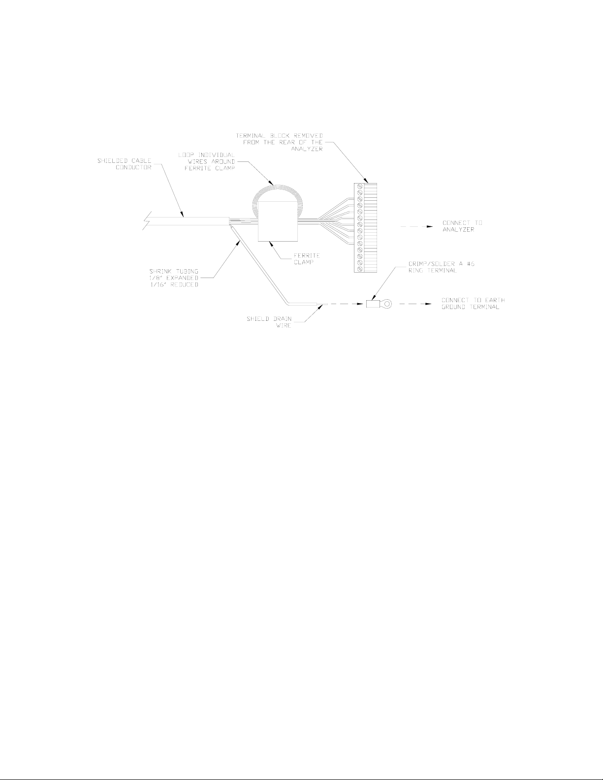
Figure 5 – Recommended electrical connection to the analyzer
terminal blocks
Manual Part Number:
5-06-4900-65-0
Revision Level: A
ECO 8541
File Name: MN-A-0177 Page 14

A label depicting the terminal block arrangement is affixed to the top
of the chassis for easy reference during installation and maintenance.
The terminal blocks feature screwed terminals. The terminal blocks are
also removable for ease of wiring or removal of the analyzer module.
CONNECTIONS
SEE MANUAL FOR
NO CONNECTION
TB1
ALARM 2
-
BAT. BU
12V DC
TB3
**
1 2
+
3
NO
TEMP
2
TB2 1
C
FAULT
3
C
54
NO C
PROCESS ANALYZER DIVISION
TRON
N
*
12
RS-232
SERVICE PORT
I-OUT
ANALOG
V-OUT
+
45
+-
67
TX-
8
RX
910
ALARM 1
20-30 VDC, 20 W
3
NO
76
NC
8
C
12
NO
109
NC
11
*
45
RTN
11
*
V-OUT
13
+
14
-
RANGE
SENSOR
DC POWER INPUT
*
GND COM VDC+ *
Figure 6 – Model 5124BE-N1-WO Electrical Connections Label
CUS
MET
SENSOR
ANALYZER
Figure 7 – Sensor Interface Cable Connection
Manual Part Number:
5-06-4900-65-0
Revision Level: A
ECO 8541
File Name: MN-A-0177 Page 15

123
TEMP
TB2 45678910 11 12 13 14
FAULT
CNO
Alarm 1
CNC NO
Alarm 2
CNC NO
Range
V-Out
+-
123
TB3 45678910 11
Bat.
BU
+-
V
Out
+-
mA
Out
+-
RS-232
TX RX RTN
12
VDC
no
connection
no
connection
Service
Port
NO = Normally
Open
NC = Normally
Closed
C = Common
VDC POWER INPUT,
18-30 VDC
13
TB1
GND
5
VDC+
24
COM
CNO
FAILSAFE
Figure 8 – Analyzer chassis electrical connections
The following is a list of all possible electrical connections to the
Model 5124BE-N1-WO analyzer:
External Sensor Interface
The Model 5124BE-N1-WO analyzer is electrically connected to the
external sensor via the sensor interface cable. Each end of the
sensor interface cable is labeled. The “ANALYZER” labeled end is to
be connected to the sensor interface socket on the analyzer. The
“SENSOR” labeled end is to be connected to the analyzer interface
socket on the external sensor.
Manual Part Number:
5-06-4900-65-0
Revision Level: A
ECO 8541
File Name: MN-A-0177 Page 16

Oxygen Alarm-1 Relay Output
Use 18-22 AWG, shielded cable for the connections. The shielded
cable must be grounded at both ends to comply with EN61326-1:2006
specifications. Loop individual connectors around the ferrite clamp
provided.
Relay Type: Form 1 C, SPDT, 5A @ 250 VAC, 5A @ 30VDC
Connections: Common: n 8Terminal Block TB2 Pi
Normally Closed Output: Terminal Block TB2 Pin 9
Normally Open Output: Terminal Block TB2 Pin 10
Oxygen Alarm-2 Relay Output
Use 18-22 AWG, shielded cable for the connections. The shielded
cable must be grounded at both ends to comply with EN61326-1:2006
specifications. Loop individual connectors around the ferrite clamp
provided.
Relay Type: Form 1 C, SPDT, 5A @ 250 VAC, 5A @ 30VDC
Connections: Common: Terminal Block TB2 Pin 5
Normally Closed Output: minal Block TB2 Pin 6Ter
Normally Open Output: Terminal Block TB2 Pin 7
System Fault Relay Output
Use 18-22 AWG, shielded cable for the connections. The shielded
cable must be grounded at both ends to comply with EN61326-1:2006
specifications. Loop individual connectors around the ferrite clamp
provided.
Relay Type: Form 1 B, SPST, 5A @ 250 VAC, 5A @ 30VDC
Connections: Common: Terminal Block TB2 Pin 3
Normally Open Output: Terminal Block TB2 Pin 4
Temperature OK Relay Output
Use 18-22 AWG, shielded cable for the connections. The shielded
cable must be grounded at both ends to comply with EN61326-1:2006
specifications. Loop individual connectors around the ferrite clamp
provided.
Relay Type: Form 1 B, SPST, 5A @ 250 VAC, 5A @ 30VDC
Connections: Common: Terminal Block TB2 Pin 1
Normally Open Output: Terminal Block TB2 Pin 2
Manual Part Number:
5-06-4900-65-0
Revision Level: A
ECO 8541
File Name: MN-A-0177 Page 17

Range ID Output
Use the Range ID voltage with either the analog voltage or the
analog current output to identify the full span oxygen concentration
measurement. Use 20-26 AWG, shielded cable for the connections.
The shielded cable must be grounded at both ends to comply with
EN61326-1:2006 specifications. Loop individual connectors around
the ferrite clamp provided.
Output Voltage: 0 - 10 Volts DC
Connections: Voltage + Output: Terminal Block TB2 Pin 13
Voltage - Output: Terminal Block TB2 Pin 14
Analog Voltage Output
The analog voltage output is factory pre-set to be either 0-1, 0-5,
or 0-10 volts. Use 20-26 AWG, shielded cable for the connections.
The shielded cable must be grounded at both ends to comply with
EN61326-1:2006 specifications. Loop individual connectors around
the ferrite clamp provided.
Output Voltage: - 10 Volts DC0 – 1, 0 – 5, or 0
Connections: Voltage + Output: Terminal Block TB3 Pin 5
Voltage - Output: Terminal Block TB3 Pin 6
Analog Current Output
The analog current output is a negative ground, non-isolated 4-20 mA
current loop. Use 20-26 AWG, shielded cable for the connections.
The shielded cable must be grounded at both ends to comply with
EN61326-1:2006 specifications. Loop individual connectors around
the ferrite clamp provided.
Output Voltage: 4 – 20 mA
Maximum Loading: 250 ohms
Connections: Current + Output: Terminal Block TB3 Pin 7
Current - Output: Terminal Block TB3 Pin 8
Battery Backup (Optional)
These terminals may be used to connect the Model 5124BE-N1-WO
analyzer to a 12V battery backup system such as a lead acid battery.
Battery backup function is not required for normal operations.
Input Voltage: 12 volts nominal
Connections: Battery + Terminal: Terminal Block TB3 Pin 3
Battery - Terminal: Terminal Block TB3 Pin 4
Manual Part Number:
5-06-4900-65-0
Revision Level: A
ECO 8541
File Name: MN-A-0177 Page 18

RS-232 Service Port
The RS-232 Service Port is used for interfacing with any standard PC
computer via the communications serial port. Use 20-26 AWG,
shielded cable for the connections. The shielded cable must be
grounded at both ends to comply with EN61326-1:2006 specifications.
Loop individual connectors around the ferrite clamp provided.
SIGNAL
DESIGNATION
AT ANALYZER
ANALYZER TB2
CONNECTION
SIGNAL
DESIGNATION
AT COMPUTER
COMPUTER DB9
SERIAL PORT
CONNECTION
TX Pin 9 RX Pin 2
RX Pin 10 TX Pin 3
RTN Pin 11 RTN Pin 5
Mains Power
Use 18-22 AWG, shielded cable for the connections. The shielded
cable must be grounded at both ends to comply with EN61326-1:2006
specifications. The ground shielding at the analyzer end is to be
connected to terminal block TB1 pin 1. Loop individual connectors
around the ferrite clamp provided.
Mains Power Voltage: ts DC18 – 30 Vol
Connections: DC +: Terminal Block TB1 Pin 4
DC -: Terminal Block TB1 Pin 2
Earth/Shield Ground: Terminal Block TB1 Pin 1
WARNING: Do not apply mains power to the analyzer or the
analyzer until all the electrical and pneumatic connections to
the analyzer and the remote sensor have been properly installed.
Manual Part Number:
5-06-4900-65-0
Revision Level: A
ECO 8541
File Name: MN-A-0177 Page 19

This manual suits for next models
1
Table of contents
Other Neutronics Analytical Instrument manuals


