New Cosmos Electric XA-4400II User manual

Model Target Gas
XA-4400II Combustible gas, H2S, CO, O2
XA-4300IIKHS Combustible gas, H2S, O2
XA-4300IIKCS Combustible gas, CO, O2
XA-4200IIKS Combustible gas, O2
XA-4200IIKH Combustible gas, H2S
XA-4200IIKC Combustible gas, CO
XA-4300IIHS O2, H2S
XA-4300IICS O2, CO
This instruction manual explains the use of eight models listed in the left.
•Keep this instruction manual available for quick reference when needed.
•Read this instruction manual and understand the information before using
the product.
Document No.: XA-4400IIT
■
XA-4400II
■
XA-4300IIKHS
■
XA-4300IIKCS
■
XA-4200IIKS
■
XA-4200IIKH
■
XA-4200IIKC
■
XA-4300IIHS
■
XA-4300IICS

3 - 4. User Mode ........................................................................................ 16
3-4-1. Switch to the User Mode.............................................................. 16
3-4-2. Changing Modes.......................................................................... 16
3-4-3. Quit the User Mode...................................................................... 17
3-4-4. Operating Procedure in Each Mode............................................. 18
(A) Alarm Test ..................................................................................... 18
(B) Each Setting.................................................................................. 20
(B-1) Buzzer ON/OFF ..................................................................... 20
(B-2) Buzzer Volume ....................................................................... 21
(B-3) Clock Adjustment ................................................................... 22
(B-4) Long Life Mode ...................................................................... 23
(C) Logging......................................................................................... 24
(C-1) Start Logging.......................................................................... 24
(C-2) Stop Logging .......................................................................... 25
(C-3) Delete Logging Data .............................................................. 25
(C-4) Logging Cycle ........................................................................ 26
4. Error Messages ........................................................................................... 27
5. Replacement of Consumables................................................................... 28
Battery Replacement ................................................................................. 28
Replacement of Filter Element................................................................... 29
Replacement of Filter for Each Sensor ...................................................... 31
6. Maintenance Check..................................................................................... 33
Daily Check................................................................................................ 33
Periodic Inspection..................................................................................... 34
Maintenance .............................................................................................. 34
Replacement Parts .................................................................................... 34
7. Troubleshooting.......................................................................................... 35
8. Warranty....................................................................................................... 36
9. Specifications.............................................................................................. 37
Multi-gas Detector...................................................................................... 37
Intrinsically Safe......................................................................................... 38
10. Disposal ..................................................................................................... 39
11. Glossary..................................................................................................... 40
Table of Contents
Included in this Package .................................................................................. 1
Options (sold separately) ................................................................................. 1
1. Introduction ................................................................................................... 2
Intrinsically Safe Requirements (Japan) ...................................................... 3
Explanation of Symbols ............................................................................... 3
Safe Operation............................................................................................. 4
2. Product Layout and Functions .................................................................... 6
Multi-gas Detector........................................................................................ 6
LCD Indication ............................................................................................. 7
3. Operating Procedure .................................................................................... 8
3 - 1. Before Using....................................................................................... 8
3-1-1. Installation of Battery ..................................................................... 8
3-1-2. How to Attach the Safety Pin Band ................................................ 8
3 - 2. Operating Procedure .......................................................................... 9
1. Turn ON the Power............................................................................... 9
2. Detection ............................................................................................ 10
3. Turn OFF the Power........................................................................... 11
Gas Concentration Display..................................................................... 11
Gas Alarm Activation .............................................................................. 12
• TWA Alarm ...................................................................................... 13
• STEL Alarm..................................................................................... 13
3 - 3. Functions in Normal Operation ......................................................... 14
3-3-1. AIR Adjustment (ZERO Adjustment) ............................................ 14
3-3-2. Peak Hold Function...................................................................... 14
3-3-3. Backlight ...................................................................................... 15
3-3-4. Buzzer Stop.................................................................................. 15
3-3-5. Alarm Set Value Indication ........................................................... 15
3-3-6. Time/Temperature Display ........................................................... 15

- 2 -
1. Introduction
Thank you for purchasing the Multi-gas Detector XA-4000II series. Be sure to read this
instruction manual and use the product properly to prevent gas accidents and for
inspection and maintenance.
This Multi-gas Detector measures up to 2 to 4 gases of oxygen (O2), combustible gas
(COMB), hydrogen sulfide (H2S) and carbon monoxide (CO), and it displays all gas
concentration values at the same time. This Multi-gas Detector gives a notification with
an alarm to help to prevent gas accidents, such as lack of oxygen, gas explosion or gas
poisoning, when the gas concentration exceeds the alarm set value.
Read and understand thoroughly this manual regardless of your experience with using
gas detector. Do not use this Multi-gas Detector for improper purposes. Do not use the
Multi-gas Detector in undocumented way in this manual.
Waterproof
Be sure to keep the gas sampling port dry.
This Multi-gas Detector employs a water proof structure which meets
our tests* complying with JIS C 0902-2003 Ingress Protection code
IPX7 at brand-new condition to prevent malfunctions due to water
from unavoidable circumstances in use. However, if the filter element
is wet, the gas cannot be detected properly. Since the age-related
deterioration of packing or label, or adhesion of foreign materials
degrade the performance of water proof structure, exposure to water
should be avoided as much as possible.
* Immerse the new Multi-gas Detector gently from the bottom into
the depth of 1m from the surface of standing tap water at room
temperature and verify that there is no damage from ingress of
water after 30 minutes.
WARNING
- 1 -
Included in this Package
The following items are enclosed in the package. Carefully check all items listed below
before use. Contact your New Cosmos representative if any items are broken or missing.
Options (sold separately)
Name (Model) Part Number Remarks
C-23 Soft Case 59540000 To protect from dirt and scratches.
Use with a Safety Pin Band.
XA-4000IIL
Datalogger Kit 59519309 Software to collect logged data to PC
Multi-gas Detector 1
BP-4000IIAL Battery Unit (attached to the Multi-gas Detector) 1
Battery Cover
(See “Battery Replacement” on page 28) 1
C-25 Safety Pin Band (with 4 screws)
(See “How to Attach the Safety Pin Band” on page 8) 1
FE-128 Filter Element (for replacement)
(See “Replacement of Filter Element” on page 29) 8
FE-129 Filter for Combustible Gas Sensor
(See “Replacement of Filter for Each Sensor” on page 31) 1
FE-130 Filter for Carbon Monoxide Sensor
(See “Replacement of Filter for Each Sensor” on page 31) 1
Panasonic Alkaline Battery (LR03/AAA) 1
Inspection Report 1
Instruction Manual 1

- 4 -
Safe Operation
Be sure to observe the following to use the product safely and properly.
DANGER When the gas alarm is sounded, take all necessary precautions
immediately to avoid explosion.
•Be sure to turn ON the Multi-gas Detector in normal condition
(clean air). Since the AIR adjustment starts automatically, the
erroneous gas concentration will be displayed in gas atmosphere.
•This Multi-gas Detector is a safety product. Perform daily check
before use (see “Daily Check” on page 33).
•Do not close the sampling port or exhaust port. The gas cannot be
detected properly.
•Do not block the buzzer port or the alarm will be hard to hear.
•Use clean filter elements. If the filter element is dirty or wet, the
gas cannot be detected properly.
•The sensor unit is guaranteed for two years from the date of
purchase. It is highly recommended to replace a sensor after two
years for proper gas detection.
•Be sure to use the specified battery. The product will not meet the
intrinsically safe requirements without the specified battery (see
“Battery Replacement” on page 28).
WARNING
- 3 -
Intrinsically Safe Requirements (Japan)
Confirm the following Intrinsically Safe Requirements.
Explanation of Symbols
The following symbols are used for safety purposes:
Indicates a hazardous situation that may result in serious injury
or death, if not avoided.
Indicates a potentially hazardous situation that may result in
serious injury or death, if not avoided.
Indicates a potentially hazardous situation that may result in
minor injury or physical damage, if not avoided.
Indicates an operational advice.
WARNING
NOTE
DANGER
WARNING
CAUTION
Intrinsically Safe Structure: Ex ia IICT3X (Japan)
Standard: Recommended Practices for Explosion-Protected Electrical Installations
in General Industries
Part 1: General Requirements, Chapter 6: Intrinsically Safe
Rating: Refer to “Intrinsically Safe Specification” on page 38
Ambient temperature: -20 to 50 degrees C
Use conditions:
・ Replace a battery and battery unit in a safe place.
・ For comprehensive measures to prevent accidents due to electrostatic charges,
the user should desirably wear anti-static working clothes and conductive
footwear (antistatic working shoes), and the floor should desirably be a
conductive work floor (leak current: 10M ohm or less).
・ In the measurement of oxygen concentration, make sure to use mix-gas of
oxygen and combustible gas, or vapor and toxic gas only.
・ The Battery Unit to connect with XA-4400II (Certificate No. TC21068) must be
BP-4000IIAL (Battery Unit, Certificate No. TC21069).
・ Use a Panasonic LR03 battery.

- 6 -
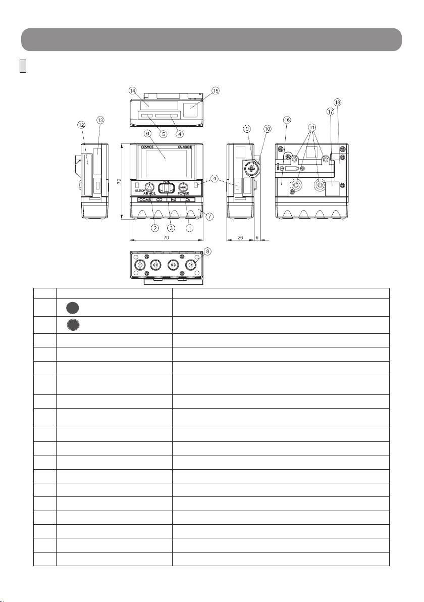
2. Product Layout and Functions
Multi-gas Detector
No. Name Functions
1 POWER Button Turn ON/OFF the power and for each setting
2 AIR ADJ. Button Automatic air adjustment, buzzer stop, each setting
3 Buzzer Hole Sounds buzzer
4 Alarm Lamp Flashing red light with alarm
5 Infrared Port Use for datalogger
6 LCD Display gas concentration and each setting
(See “LCD Indication” on page 7)
7 Sensor Cover Fix the sensor and filter element
8 Gas Detection Port
(with filter element)
Gas inlet to the sensor
(prevent the entrance of dust or water from the inlet)
9 Battery Cover For replacing a battery
10 Battery Unit The battery and associated circuit
11 Fixing Screws To attach the safety pin band
12 Serial No. of BP-4000II Model, serial number, manufactured date
13 Intrinsically Safe of XA-4400II Intrinsically safe structure, temperature, specification No.
14 Serial No. of XA-4400II Model, serial number, manufactured date
15 Certificate Label of XA-4400II
16 Intrinsically Safe of BP-4000II Intrinsically safe structure, temperature, specification No.
17 Certificate Label of BP-4000II
18 Warning Label
(Top)
(Front)
(Bottom)
(Back)
MENU
▲
- 5 -
CAUTION •Remove the battery for long term storage to avoid any possible
damage to the Multi-gas Detector due to the battery leakage.
•XA-4400II is an intrinsically safe Multi-gas Detector. Do not
attempt to disassemble, remodel, modify of structure or circuit,
etc., as it may affect the performance.
•Keep the Multi-gas Detector away from heat and moisture as it
may affect the performance.
•Do not use in the condition out of the operating temperature,
humidity or pressure range and avoid sudden change of
temperature or humidity, as it may affect the performance.
•Avoid rapid changes in pressure, as it may affect the sensor
performance or it may cause damage to the product.
•Do not drop or hit the Multi-gas detector to avoid mechanical
impact and strong vibration, as it may affect the performance.
•If the Multi-gas Detector is dropped or hit and the reading
fluctuates, allow enough time to stabilize the reading before use.
•In case of condensation, dry the Multi-gas Detector completely
and check the performance before use.
•Use the Multi-gas Detector in suitable environment to avoid
detection of other interference gas or solvent vapor.
•Do not use the Multi-gas Detector in an atmosphere containing
silicone gas or silicone products, as it may affect the performance.
•Detecting high concentration of sulfur dioxide or chlorine may
decrease sensor life or increase errors.
•Detecting hydrogen sulfide for a long period of time may decrease
sensor life or the sensor sensitivity.
•Make the pressure correction when detecting gas at places where
the atmospheric pressure is different from the standard, such as
high altitude places, due to the pressure dependence of oxygen
sensor.
•The gas sensor contains toxic substances. When disposing of the
sensor, return to New Cosmos Electric or treat it as industrial
waste.
•Low temperature may shorten the battery life due to the battery
property.
•Keep wireless devices away from the Multi-gas Detector while in
use, as it may cause fluctuation in the reading or may cause
alarm errors due to radio waves.
•The vibration alarm may be difficult to notice depending on the
wearing position.
- 6 -
2. Product Layout and Functions
Multi-gas Detector
No. Name Functions
1 POWER Button Turn ON/OFF the power and for each setting
2 AIR ADJ. Button Automatic air adjustment, buzzer stop, each setting
3 Buzzer Hole Sounds buzzer
4 Alarm Lamp Flashing red light with alarm
5 Infrared Port Use for datalogger
6 LCD Display gas concentration and each setting
(See “LCD Indication” on page 7)
7 Sensor Cover Fix the sensor and filter element
8 Gas Detection Port
(with filter element)
Gas inlet to the sensor
(prevent the entrance of dust or water from the inlet)
9 Battery Cover For replacing a battery
10 Battery Unit The battery and associated circuit
11 Fixing Screws To attach the safety pin band
12 Serial No. of BP-4000II Model, serial number, manufactured date
13 Intrinsically Safe of XA-4400II Intrinsically safe structure, temperature, specification No.
14 Serial No. of XA-4400II Model, serial number, manufactured date
15 Certificate Label of XA-4400II
16 Intrinsically Safe of BP-4000II Intrinsically safe structure, temperature, specification No.
17 Certificate Label of BP-4000II
18 Warning Label
(Top)
(Front)
(Bottom)
(Back)
MENU
▲
- 5 -
CAUTION •Remove the battery for long term storage to avoid any possible
damage to the Multi-gas Detector due to the battery leakage.
•XA-4400II is an intrinsically safe Multi-gas Detector. Do not
attempt to disassemble, remodel, modify of structure or circuit,
etc., as it may affect the performance.
•Keep the Multi-gas Detector away from heat and moisture as it
may affect the performance.
•Do not use in the condition out of the operating temperature,
humidity or pressure range and avoid sudden change of
temperature or humidity, as it may affect the performance.
•Avoid rapid changes in pressure, as it may affect the sensor
performance or it may cause damage to the product.
•Do not drop or hit the Multi-gas detector to avoid mechanical
impact and strong vibration, as it may affect the performance.
•If the Multi-gas Detector is dropped or hit and the reading
fluctuates, allow enough time to stabilize the reading before use.
•In case of condensation, dry the Multi-gas Detector completely
and check the performance before use.
•Use the Multi-gas Detector in suitable environment to avoid
detection of other interference gas or solvent vapor.
•Do not use the Multi-gas Detector in an atmosphere containing
silicone gas or silicone products, as it may affect the performance.
•Detecting high concentration of sulfur dioxide or chlorine may
decrease sensor life or increase errors.
•Detecting hydrogen sulfide for a long period of time may decrease
sensor life or the sensor sensitivity.
•Make the pressure correction when detecting gas at places where
the atmospheric pressure is different from the standard, such as
high altitude places, due to the pressure dependence of oxygen
sensor.
•The gas sensor contains toxic substances. When disposing of the
sensor, return to New Cosmos Electric or treat it as industrial
waste.
•Low temperature may shorten the battery life due to the battery
property.
•Keep wireless devices away from the Multi-gas Detector while in
use, as it may cause fluctuation in the reading or may cause
alarm errors due to radio waves.
•The vibration alarm may be difficult to notice depending on the
wearing position.

- 8 -
3. Operating Procedure
3 - 1. Before Using
3-1-1. Installation of Battery
Install the supplied Panasonic alkaline battery (LR03/AAA). (See “Battery Replacement”
on page 28)
The battery cover is not fixed to the Multi-gas Detector but included in the packing box
from the shipment.
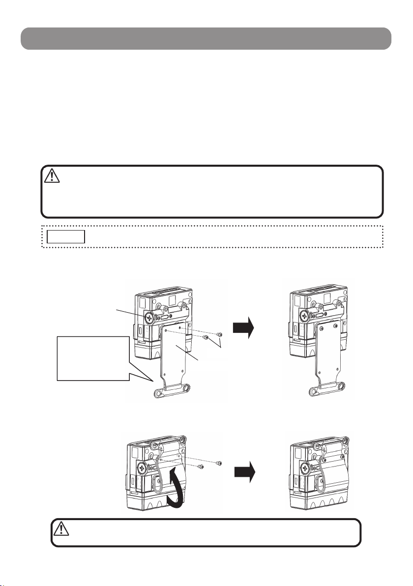
3-1-2. How to Attach the Safety Pin Band
1) Screw the Safety Pin Band to the bottom of battery compartment with supplied two
fixing screws. (Pay attention to the direction of safety pin)
2) Bend the Safety Pin Band upward and screw to the top of battery compartment with
supplied two fixing screws.
WARNING
Fixing Screws
Safety Pin Band
Let the direction
of safety pin
needle be the
battery cover side
Battery Cover
Please note that the safety pin may leave a tiny hole in clothes.
NOTE
Be careful not to block or cover the detection port, as it cannot
detect properly.
•Use only the supplied screws (M2.6 x 4, truss head).
•Use a screwdriver with point size 1 (see on page 32 for the
shapes).
•Careful not to prick your finger with the safety pin.
CAUTION
- 7 -
LCD Indication
No.
Functions Ref.
1 Displays concentration and setting -
2 Gas type Page 11
3 2nd alarm
4 1st alarm Page 12
5 Displays the unit of concentration -
6 Battery level indication Page 28
7 Alarm level indication Page 21
8 Buzzer silent mode indication Page 20
9 Peak hold value Page 14
10 Long-life mode indication Page 23
11 Displays each setting -
12 Temperature scale Page 15
13 Operating combustible gas sensor
indication -
2
3
4
5
1
6 7 8 9 10 12 13 11
- 8 -
3. Operating Procedure
3 - 1. Before Using
3-1-1. Installation of Battery
Install the supplied Panasonic alkaline battery (LR03/AAA). (See “Battery Replacement”
on page 28)
The battery cover is not fixed to the Multi-gas Detector but included in the packing box
from the shipment.
3-1-2. How to Attach the Safety Pin Band
1) Screw the Safety Pin Band to the bottom of battery compartment with supplied two
fixing screws. (Pay attention to the direction of safety pin)
2) Bend the Safety Pin Band upward and screw to the top of battery compartment with
supplied two fixing screws.
WARNING
Fixing Screws
Safety Pin Band
Let the direction
of safety pin
needle be the
battery cover side
Battery Cover
Please note that the safety pin may leave a tiny hole in clothes.
NOTE
Be careful not to block or cover the detection port, as it cannot
detect properly.
•Use only the supplied screws (M2.6 x 4, truss head).
•Use a screwdriver with point size 1 (see on page 32 for the
shapes).
•Careful not to prick your finger with the safety pin.
CAUTION
- 7 -
LCD Indication
No. Functions Ref.
1 Displays concentration and setting -
2 Gas type Page 11
3 2nd alarm
4 1st alarm Page 12
5 Displays the unit of concentration -
6 Battery level indication Page 28
7 Alarm level indication Page 21
8 Buzzer silent mode indication Page 20
9 Peak hold value Page 14
10 Long-life mode indication Page 23
11 Displays each setting -
12 Temperature scale Page 15
13 Operating combustible gas sensor
indication -
2
3
4
5
1
6 7 8 9 10 12 13 11
- 10 -
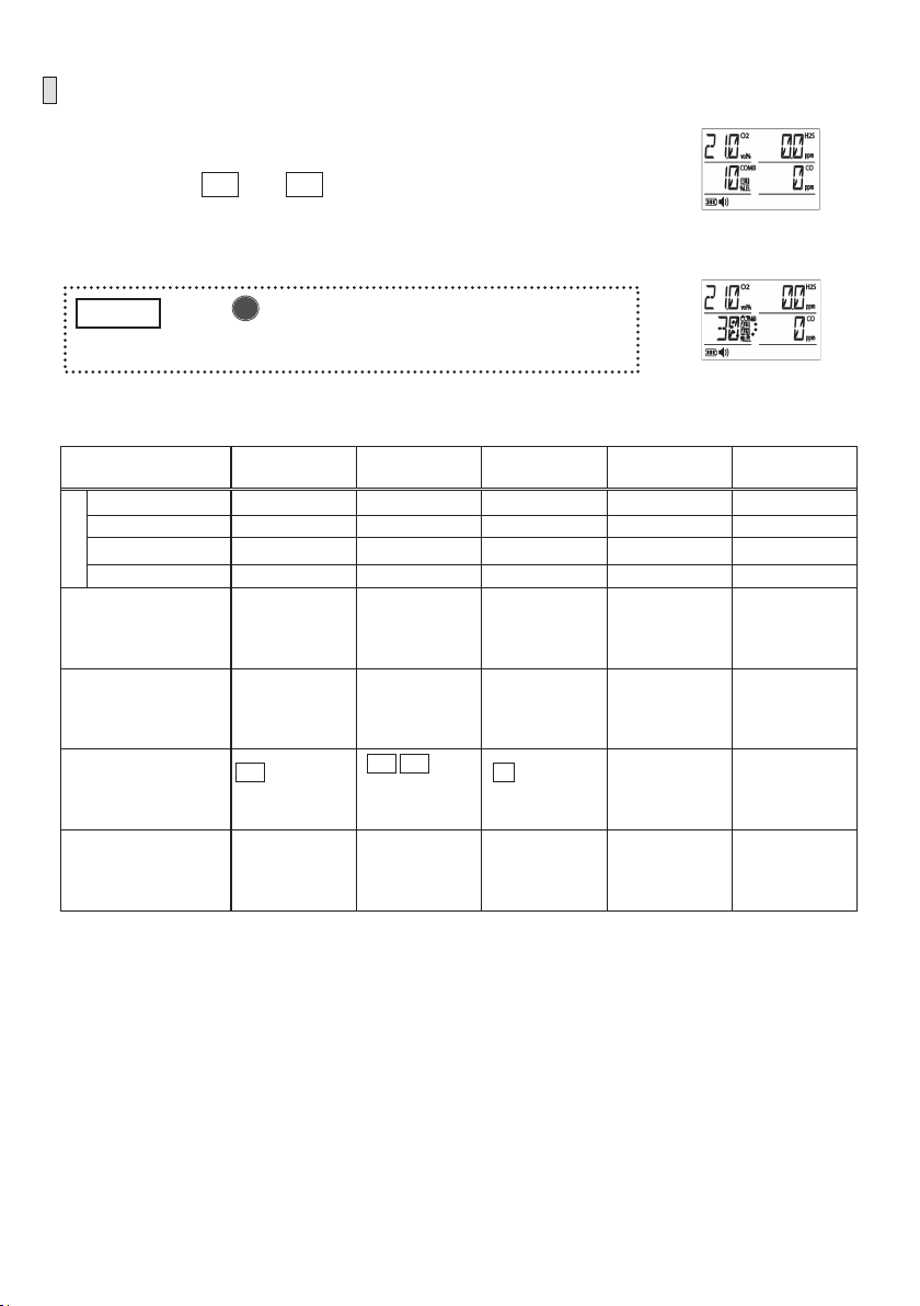
2. Detection
When <Gas Concentration Display> is displayed, the
Multi-gas Detector is ready for use.
--> See “LCD Indication” on page 7
--> See “Gas Concentration Display” on page 11
--> See “Gas Alarm Activation” on page 12
<Gas Concentration Display>
WARNING •Do not block the detection port as it cannot detect gases.
•Keep the filter element dry and clean. If the filter element
becomes dirty or wet, it may affect the detection performance.
•Keep the gas detection port dry from rain or water when
wearing the Multi-gas Detector.
•When the reading exceeds full scale, move the Multi-gas
Detector to the clean air immediately, as it may become slow to
return to the base or it may affect the detection performance.
•Careful not to block the buzzer port as the alarm volume may
be too small to notice.
For button operation, a “press” is less than one second, and “press and hold”
is about three seconds.
NOTE
CAUTION •A significant change in temperature or humidity at work
environment may affect the concentration values of 21.0vol%,
0%LEL and 0ppm. In this case, press and hold the [ AIR
ADJ.] button to start “AIR Adjustment (Zero Adjustment)” (page
14) in the clean air.
•Blinking “0” or “0.0” of gas concentration
indicates negative value. In this case, high
concentration gas may have been detected,
or AIR Adjustment may have been performed
in gas atmosphere.
Perform “AIR Adjustment (Zero Adjustment)” (page 14) in the
clean air. If [E-S] is displayed (page 27), turn OFF and ON the
power in the clean air.
•The vibration alarm may be difficult to notice depending on the
wearing position.
Blinking
▲
- 9 -
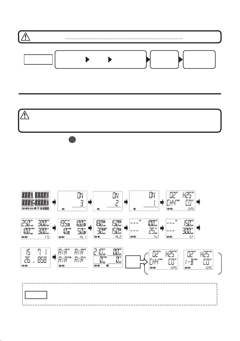
3 - 2. Operating Procedure
* In this instruction manual describes for the target gases of oxygen, combustible gas
(methane), hydrogen sulfide, and carbon monoxide.
1. Turn ON the Power -> Warm-up -> Displays <Gas Concentration Display>
Press and hold the [ POWER] button to switch into <Gas Type Display>.
After a beep, all segments are displayed on the LCD, “ON” appears, and the countdown
starts: 3, 2, 1. Release the button after a bleep.
Then <Gas Type Display>, <Full Scale>, <AL1 Alarm Set Value>, <AL2 Alarm Set
Value>, <TWA Alarm Set Value>, <STEL Alarm Set Value> and <Time/Temperature>
will be displayed automatically. After <Air Adjustment> and the warm-up operation is
completed, it switches into <Gas Concentration Display> after three beep sounds.
•The warm-up operation will take about a maximum of 2 minutes.
•Only the power OFF button is available while the warm-up operation.
•In case of an error occurs, see “Error Messages” on page 27.
Make sure to turn ON the power in the clean air. Since the air
adjustment starts automatically, the erroneous gas concentration
will be displayed in gas atmosphere.
NOTE
Alwa
y
s perform Maintenance Check
(
pa
g
e 33
)
before use.
MENU
Warm-
up
Displays <Gas
Concentration
Display>
1. Turn ON 2. Detection 3. Turn OFF
STEPS
<All Segments> <Gas Type Display>
<Full Scale> <AL1 Alarm Set> <AL2 Alarm Set> <TWA Alarm Set> <STEL Alarm Set>
<Time/Temperature> <Air Adjustment> <Gas Concentration> <For methane> <For isobutane>
Gas
Type
Display
WARNING
WARNING

- 10 -
2. Detection
When <Gas Concentration Display> is displayed, the
Multi-gas Detector is ready for use.
--> See “LCD Indication” on page 7
--> See “Gas Concentration Display” on page 11
--> See “Gas Alarm Activation” on page 12
<Gas Concentration Display>
WARNING •Do not block the detection port as it cannot detect gases.
•Keep the filter element dry and clean. If the filter element
becomes dirty or wet, it may affect the detection performance.
•Keep the gas detection port dry from rain or water when
wearing the Multi-gas Detector.
•When the reading exceeds full scale, move the Multi-gas
Detector to the clean air immediately, as it may become slow to
return to the base or it may affect the detection performance.
•Careful not to block the buzzer port as the alarm volume may
be too small to notice.
For button operation, a “press” is less than one second, and “press and hold”
is about three seconds.
NOTE
CAUTION •A significant change in temperature or humidity at work
environment may affect the concentration values of 21.0vol%,
0%LEL and 0ppm. In this case, press and hold the [ AIR
ADJ.] button to start “AIR Adjustment (Zero Adjustment)” (page
14) in the clean air.
•Blinking “0” or “0.0” of gas concentration
indicates negative value. In this case, high
concentration gas may have been detected,
or AIR Adjustment may have been performed
in gas atmosphere.
Perform “AIR Adjustment (Zero Adjustment)” (page 14) in the
clean air. If [E-S] is displayed (page 27), turn OFF and ON the
power in the clean air.
•The vibration alarm may be difficult to notice depending on the
wearing position.
Blinking
▲
- 9 -
3 - 2. Operating Procedure
* In this instruction manual describes for the target gases of oxygen, combustible gas
(methane), hydrogen sulfide, and carbon monoxide.
1. Turn ON the Power -> Warm-up -> Displays <Gas Concentration Display>
Press and hold the [ POWER] button to switch into <Gas Type Display>.
After a beep, all segments are displayed on the LCD, “ON” appears, and the countdown
starts: 3, 2, 1. Release the button after a bleep.
Then <Gas Type Display>, <Full Scale>, <AL1 Alarm Set Value>, <AL2 Alarm Set
Value>, <TWA Alarm Set Value>, <STEL Alarm Set Value> and <Time/Temperature>
will be displayed automatically. After <Air Adjustment> and the warm-up operation is
completed, it switches into <Gas Concentration Display> after three beep sounds.
•The warm-up operation will take about a maximum of 2 minutes.
•Only the power OFF button is available while the warm-up operation.
•In case of an error occurs, see “Error Messages” on page 27.
Make sure to turn ON the power in the clean air. Since the air
adjustment starts automatically, the erroneous gas concentration
will be displayed in gas atmosphere.
NOTE
Alwa
y
s perform Maintenance Check
(
pa
g
e 33
)
before use.
MENU
Warm-
up
Displays <Gas
Concentration
Display>
1. Turn ON 2. Detection 3. Turn OFF
STEPS
<All Segments> <Gas Type Display>
<Full Scale> <AL1 Alarm Set> <AL2 Alarm Set> <TWA Alarm Set> <STEL Alarm Set>
<Time/Temperature> <Air Adjustment> <Gas Concentration> <For methane> <For isobutane>
Gas
Type
Display
WARNING
WARNING
- 12 -
Gas Alarm Activation
When the gas concentration exceeds the alarm level, corresponding
gas concentration will blink, buzzer will sound intermittently, alarm
lamp will blink, AL1 and AL2 will appear on the LCD, backlight will
be on, and intermittent vibration will activate.
When the gas concentration falls below the alarm level, the gas
alarm will deactivate automatically (automatic reset).
Alarm Output 1st Alarm 2nd Alarm OL Alarm TWA Alarm STEL Alarm
Combustible Gas 10%LEL 30%LEL 111%LEL --
Oxygen 19.5vol% 18.0vol% 50.1vol% --
Hydrogen Sulfide 10.0ppm 15.0ppm 150.1ppm 10.0ppm 15.0ppm
Gas Type
Carbon Monoxide 50ppm 150ppm 2001ppm 25ppm 300ppm
Buzzer Sound
Slow
intermittent
sound
Fast
intermittent
sound
Same as 2nd
alarm
Same as 1st
alarm
Same as 1st
alarm
Alarm Lamp (3-point)
3 lamps blink
sequentially in
5sec period
3 lamps blink
sequentially in
0.8sec period
Same as 2nd
alarm
Same as 1st
alarm
Same as 1st
alarm
LCD
AL1 appears on
corresponding
gas part
AL1 AL2
appear on
corresponding
gas part
OL appears on
corresponding
gas part
[TOO] blinks in
the lower right
corner (see the
next page)
[SOO] blinks in
the lower right
corner (see the
next page)
Vibration
Intermittent
vibration in
2.5sec period
Intermittent
vibration in
2.5sec period
Same as 2nd
alarm
Same as 1st
alarm
Same as 1st
alarm
1s
t
alarm:
Combustible gas
2n
d
alarm:
Combustible gas
Tap [ AIR ADJ.] button to stop buzzer sound during
alarm. However if a new alarm arises, buzzer will
sound intermittently.
NOTE ▲
- 11 -
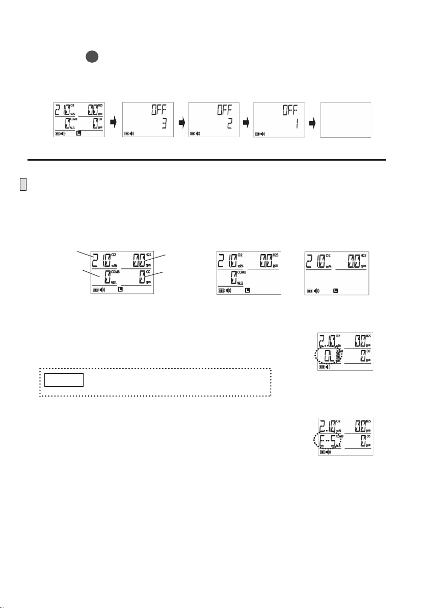
3. Turn OFF the Power
Press the [ POWER] button to turn OFF the screen.
--> After a beep, “OFF” appears, the countdown starts 3, 2, 1, and then the LCD and the
power will be turned OFF with three beep sounds.
Gas Concentration Display
Up to four types of gas concentration will be displayed on the LCD at the same time. For
2-gas or 3-gas type model, only the target gas names and concentrations will be displayed.
(The following diagrams describe for 4-gas type models.)
•When the gas concentration exceeds the service range
(see "Specifications" on page 37), "OL" will be blinking
on the concentration display.
•If the detection failure is caused by sensor error, the
error message “E-S” will appear on the corresponding
sensor display. (See “Error Messages” on page 27)
MENU
<OFF>
<Gas Concentration Display>
See the chart on page 12 for the details on
concentration indicating “OL”.
NOTE
3-gas Type 2-gas Type
4-gas Type
Combustible
Gas
Oxygen
Carbon
Monoxide
Hydrogen
Sulfide
Exceeding the range of
combustible gas sensor
Blinking
Sensor error of
combustible gas
Blinking
- 12 -
Gas Alarm Activation
When the gas concentration exceeds the alarm level, corresponding
gas concentration will blink, buzzer will sound intermittently, alarm
lamp will blink, AL1 and AL2 will appear on the LCD, backlight will
be on, and intermittent vibration will activate.
When the gas concentration falls below the alarm level, the gas
alarm will deactivate automatically (automatic reset).
Alarm Output 1st Alarm 2nd Alarm OL Alarm TWA Alarm STEL Alarm
Combustible Gas 10%LEL 30%LEL 111%LEL --
Oxygen 19.5vol% 18.0vol% 50.1vol% --
Hydrogen Sulfide 10.0ppm 15.0ppm 150.1ppm 10.0ppm 15.0ppm
Gas Type
Carbon Monoxide 50ppm 150ppm 2001ppm 25ppm 300ppm
Buzzer Sound
Slow
intermittent
sound
Fast
intermittent
sound
Same as 2nd
alarm
Same as 1st
alarm
Same as 1st
alarm
Alarm Lamp (3-point)
3 lamps blink
sequentially in
5sec period
3 lamps blink
sequentially in
0.8sec period
Same as 2nd
alarm
Same as 1st
alarm
Same as 1st
alarm
LCD
AL1 appears on
corresponding
gas part
AL1 AL2
appear on
corresponding
gas part
OL appears on
corresponding
gas part
[TOO] blinks in
the lower right
corner (see the
next page)
[SOO] blinks in
the lower right
corner (see the
next page)
Vibration
Intermittent
vibration in
2.5sec period
Intermittent
vibration in
2.5sec period
Same as 2nd
alarm
Same as 1st
alarm
Same as 1st
alarm
1s
t
alarm:
Combustible gas
2n
d
alarm:
Combustible gas
Tap [ AIR ADJ.] button to stop buzzer sound during
alarm. However if a new alarm arises, buzzer will
sound intermittently.
NOTE ▲
- 11 -
3. Turn OFF the Power
Press the [ POWER] button to turn OFF the screen.
--> After a beep, “OFF” appears, the countdown starts 3, 2, 1, and then the LCD and the
power will be turned OFF with three beep sounds.
Gas Concentration Display
Up to four types of gas concentration will be displayed on the LCD at the same time. For
2-gas or 3-gas type model, only the target gas names and concentrations will be displayed.
(The following diagrams describe for 4-gas type models.)
•When the gas concentration exceeds the service range
(see "Specifications" on page 37), "OL" will be blinking
on the concentration display.
•If the detection failure is caused by sensor error, the
error message “E-S” will appear on the corresponding
sensor display. (See “Error Messages” on page 27)
MENU
<OFF>
<Gas Concentration Display>
See the chart on page 12 for the details on
concentration indicating “OL”.
NOTE
3-gas Type 2-gas Type
4-gas Type
Combustible
Gas
Oxygen
Carbon
Monoxide
Hydrogen
Sulfide
Exceeding the range of
combustible gas sensor
Blinking
Sensor error of
combustible gas
Blinking

- 14 -
3 - 3. Functions in Normal Operation
The detailed function descriptions in the normal operation are as below.
“Normal Operation” is the enable condition after the power in ON and the display is
<Gas Concentration Display>.
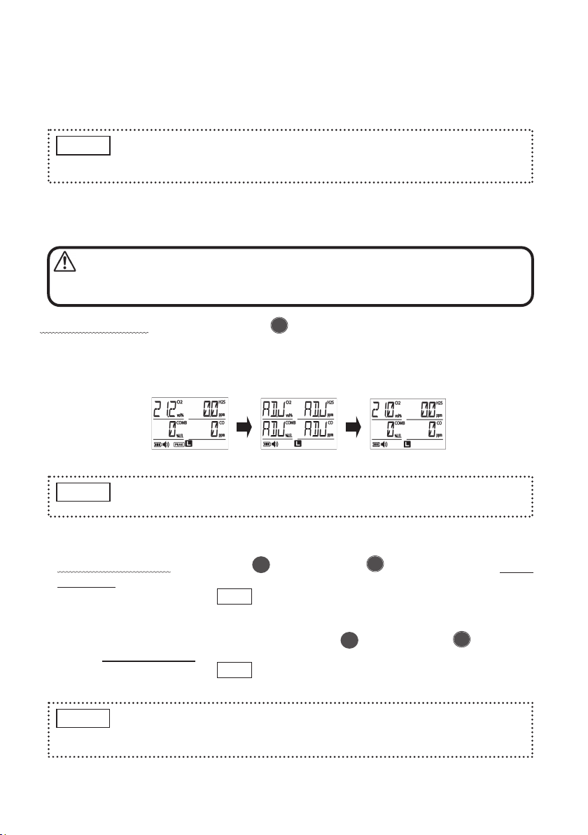
3-3-1. AIR Adjustment (ZERO Adjustment)
In normal operation, press and hold the [ AIR ADJ.] button for 3 seconds.
--> A beep will sound three times and [ADJ] will be displayed on the detectable gas
concentration display for 3 seconds. When the AIR Adjustment (ZERO adjustment) is
completed, [21.0vol%], [0%LEL] and [0ppm] will be displayed.
3-3-2. Peak Hold Function
1) In normal operation, press both [ POWER] and [ AIR ADJ.] buttons at the
same time.
--> A beep will sound once, PEAK will be displayed in the bottom of the LCD, and it
starts updating the current peak value (maximum value; minimum value for
oxygen).
2) To cancel the Peak Hold Function, press both [ POWER] and [ AIR ADJ.]
buttons at the same time again.
--> A beep will sound once, PEAK will be off, the peak value will be reset, and it will
revert to the normal <Gas Concentration Display> (instantaneous value).
Make sure to perform AIR Adjustment (ZERO Adjustment) in the
clean air. The erroneous gas concentration will be displayed in
gas atmosphere.
(Completed)(Oxygen is 21.2%) (AIR Adjustment)
For the gas, which the AIR Adjustment cannot be performed, the concentration
will be displayed instead of [ADJ].
NOTE
In "Functions in Normal Operation", the Multi-Gas Detector detects even if the
gas concentration is not displayed, and the gas alarm will be activated when it
exceeds the alarm set value.
NOTE
MENU
MENU
•The peak hold function will be canceled if the power is turned OFF.
•When the peak hold function is on, it will keep updating the current peak
value even if the concentration is decreased.
NOTE
WARNING
▲
▲
▲
- 13 -
•TWA Alarm
Hydrogen sulfide (H2S) and carbon monoxide (CO) concentrations will be integrated
every minute while the power is ON. The alarm will be activated when the integrated
value exceeds the alarm set value (see “Specifications” on page 37), and the indication
will be blinking in the bottom right corner of the LCD as below.
[(Integrated) Value]
Hydrogen Sulfide: 10 ppm x 8 hours x 60 times (60 times/hour) = 4,800 ppm
Carbon Monoxide: 25 ppm x 8 hours x 60 times (60 times/hour) = 12,000ppm
•STEL Alarm
When a 15-minute TWA exposure for hydrogen sulfide (H2S) and carbon monoxide
(CO) exceeds the alarm set value, the alarm will be activated and the indication will be
blinking in the bottom right corner of the LCD as below.
DANGER
Blinking
(for CO) Blinking
(for CO and H2S)
Blinking
(for H2S)
Blinking (for H2S)
(for CO) (for CO and H2S)
Blinking
Blinking
TWA alarm will not be reset until the power is turned OFF.
NOTE
STEL alarm will not be reset until it falls below the average or
the power is turned OFF.
NOTE
When the gas alarm is sounded, take all necessary precautions
immediately to avoid explosion.
- 14 -
3 - 3. Functions in Normal Operation
The detailed function descriptions in the normal operation are as below.
“Normal Operation” is the enable condition after the power in ON and the display is
<Gas Concentration Display>.
3-3-1. AIR Adjustment (ZERO Adjustment)
In normal operation, press and hold the [ AIR ADJ.] button for 3 seconds.
--> A beep will sound three times and [ADJ] will be displayed on the detectable gas
concentration display for 3 seconds. When the AIR Adjustment (ZERO adjustment) is
completed, [21.0vol%], [0%LEL] and [0ppm] will be displayed.
3-3-2. Peak Hold Function
1) In normal operation, press both [ POWER] and [ AIR ADJ.] buttons at the
same time.
--> A beep will sound once, PEAK will be displayed in the bottom of the LCD, and it
starts updating the current peak value (maximum value; minimum value for
oxygen).
2) To cancel the Peak Hold Function, press both [ POWER] and [ AIR ADJ.]
buttons at the same time again.
--> A beep will sound once, PEAK will be off, the peak value will be reset, and it will
revert to the normal <Gas Concentration Display> (instantaneous value).
Make sure to perform AIR Adjustment (ZERO Adjustment) in the
clean air. The erroneous gas concentration will be displayed in
gas atmosphere.
(Completed)(Oxygen is 21.2%) (AIR Adjustment)
For the gas, which the AIR Adjustment cannot be performed, the concentration
will be displayed instead of [ADJ].
NOTE
In "Functions in Normal Operation", the Multi-Gas Detector detects even if the
gas concentration is not displayed, and the gas alarm will be activated when it
exceeds the alarm set value.
NOTE
MENU
MENU
•The peak hold function will be canceled if the power is turned OFF.
•When the peak hold function is on, it will keep updating the current peak
value even if the concentration is decreased.
NOTE
WARNING
▲
▲
▲
- 13 -
•TWA Alarm
Hydrogen sulfide (H2S) and carbon monoxide (CO) concentrations will be integrated
every minute while the power is ON. The alarm will be activated when the integrated
value exceeds the alarm set value (see “Specifications” on page 37), and the indication
will be blinking in the bottom right corner of the LCD as below.
[(Integrated) Value]
Hydrogen Sulfide: 10 ppm x 8 hours x 60 times (60 times/hour) = 4,800 ppm
Carbon Monoxide: 25 ppm x 8 hours x 60 times (60 times/hour) = 12,000ppm
•STEL Alarm
When a 15-minute TWA exposure for hydrogen sulfide (H2S) and carbon monoxide
(CO) exceeds the alarm set value, the alarm will be activated and the indication will be
blinking in the bottom right corner of the LCD as below.
DANGER
Blinking
(for CO) Blinking
(for CO and H2S)
Blinking
(for H2S)
Blinking (for H2S)
(for CO) (for CO and H2S)
Blinking
Blinking
TWA alarm will not be reset until the power is turned OFF.
NOTE
STEL alarm will not be reset until it falls below the average or
the power is turned OFF.
NOTE
When the gas alarm is sounded, take all necessary precautions
immediately to avoid explosion.
- 16 -
3 - 4. User Mode
In the User Mode, change the setting of “alarm test”, “various setting (of buzzer ON/OFF,
buzzer volume, clock adjustment, and long-life mode)” and “datalogger”.
3-4-1. Switch to the User Mode
In normal operation, press the [ POWER] button for 1 second and release.
--> A beep will sound once, and it will switch into the user mode displaying “AL TEST”
(alarm test).
3-4-2. Changing Modes
Press the [ AIR ADJ.] button to <<Select>>.
--> Each time pressing the button, [AL TEST] (alarm test), [SET UP] (each setting),
and [LOG] (logging) will be displayed sequentially.
Select the mode to change and press both [ POWER] and [ AIR ADJ.] buttons
at the same time.
--> The mode switches with a beep sound.
(See the next page for the functions and setting of each mode)
If it is not operated for 1 minute in the user mode, it will revert to the <Gas
Concentration Display> automatically.
NOTE
MENU
<Gas Concentration Display>
MENU
•It is unable to detect gas in the user mode.
•The setting in the user mode will be kept, even if the power is
turned OFF or the battery is removed.
WARNING
▲
▲
▲ ▲ ▲
<Alarm Test> <Each Setting>
・Buzzer ON/OFF
・Buzzer Volume
・Clock Adjustment
・Long-life Mode
<Logging>
- 15 -
3-3-3. Backlight
LCD backlight will be on automatically when the gas alarm is activated, and it will be
off when the gas alarm is released. Pressing the [ POWER] or [ AIR ADJ.]
button will turn the backlight on, and the light will be off automatically 5 seconds after
the operation.
3-3-4. Buzzer Stop
Press the [ AIR ADJ.] button to stop the buzzer sound while a gas alarm is
activated, an error is occurred, or when a battery is dead.
3-3-5. Alarm Set Value Indication
In normal operation, press the [ AIR ADJ.] button.
--> Full scale, 1st alarm set value, 2nd alarm set value, TWA alarm set value, and STEL
alarm set value of each gas will be displayed on the LCD for 2 second, and then
will revert to <Gas Concentration Display> automatically.
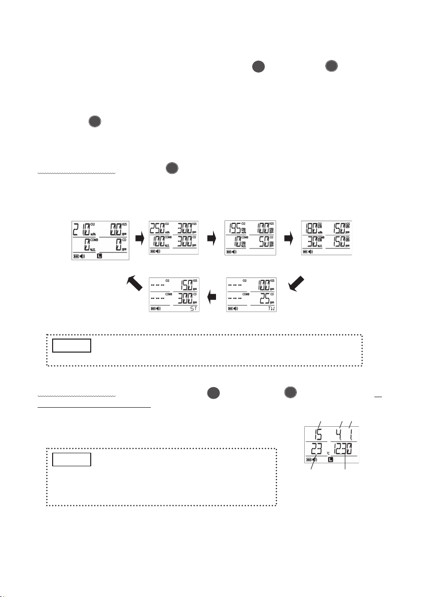
3-3-6. Time/Temperature Display
In normal operation, press and hold both [ POWER] and [ AIR ADJ.] buttons at
the same time for 3 seconds.
--> Date, time and temperature will be displayed on the LCD
for 5 seconds, and then will revert to <Gas
Concentration Display> automatically.
MENU
<Gas Concentration Display>
(Normal Operation)
<1s
t
Stage Alarm Set Value><Full Scale>
<TWA Alarm Set Value>
<STEL Alarm Set Value>
Please contact New Cosmos Electric for changing the alarm set value.
NOTE
MENU
<Time/Temperature Display>
Year Month Day
Temperature Time
•Year is the last two digits of the year on
the LCD.
•Since a temperature sensor is built inside
the Multi-gas Detector, use the indicated
temperature as a guide.
NOTE
▲
▲
▲
▲
<2n
d
Stage Alarm Set Value>

- 16 -
3 - 4. User Mode
In the User Mode, change the setting of “alarm test”, “various setting (of buzzer ON/OFF,
buzzer volume, clock adjustment, and long-life mode)” and “datalogger”.
3-4-1. Switch to the User Mode
In normal operation, press the [ POWER] button for 1 second and release.
--> A beep will sound once, and it will switch into the user mode displaying “AL TEST”
(alarm test).
3-4-2. Changing Modes
Press the [ AIR ADJ.] button to <<Select>>.
--> Each time pressing the button, [AL TEST] (alarm test), [SET UP] (each setting),
and [LOG] (logging) will be displayed sequentially.
Select the mode to change and press both [ POWER] and [ AIR ADJ.] buttons
at the same time.
--> The mode switches with a beep sound.
(See the next page for the functions and setting of each mode)
If it is not operated for 1 minute in the user mode, it will revert to the <Gas
Concentration Display> automatically.
NOTE
MENU
<Gas Concentration Display>
MENU
•It is unable to detect gas in the user mode.
•The setting in the user mode will be kept, even if the power is
turned OFF or the battery is removed.
WARNING
▲
▲
▲ ▲ ▲
<Alarm Test> <Each Setting>
・Buzzer ON/OFF
・Buzzer Volume
・Clock Adjustment
・Long-life Mode
<Logging>
- 15 -
3-3-3. Backlight
LCD backlight will be on automatically when the gas alarm is activated, and it will be
off when the gas alarm is released. Pressing the [ POWER] or [ AIR ADJ.]
button will turn the backlight on, and the light will be off automatically 5 seconds after
the operation.
3-3-4. Buzzer Stop
Press the [ AIR ADJ.] button to stop the buzzer sound while a gas alarm is
activated, an error is occurred, or when a battery is dead.
3-3-5. Alarm Set Value Indication
In normal operation, press the [ AIR ADJ.] button.
--> Full scale, 1st alarm set value, 2nd alarm set value, TWA alarm set value, and STEL
alarm set value of each gas will be displayed on the LCD for 2 second, and then
will revert to <Gas Concentration Display> automatically.
3-3-6. Time/Temperature Display
In normal operation, press and hold both [ POWER] and [ AIR ADJ.] buttons at
the same time for 3 seconds.
--> Date, time and temperature will be displayed on the LCD
for 5 seconds, and then will revert to <Gas
Concentration Display> automatically.
MENU
<Gas Concentration Display>
(Normal Operation)
<1s
t
Stage Alarm Set Value><Full Scale>
<TWA Alarm Set Value>
<STEL Alarm Set Value>
Please contact New Cosmos Electric for changing the alarm set value.
NOTE
MENU
<Time/Temperature Display>
Year Month Day
Temperature Time
•Year is the last two digits of the year on
the LCD.
•Since a temperature sensor is built inside
the Multi-gas Detector, use the indicated
temperature as a guide.
NOTE
▲
▲
▲
▲
<2n
d
Stage Alarm Set Value>

- 18 -
▲MENU
3-4-4. Operating Procedure in Each Mode
Functions of each button are listed below.
•Select: Press the [ AIR ADJ.] button for 1 second.
(The item will switch sequentially each time
pressing the button)
•Choose: Press both [ AIR ADJ.] and [ POWER]
buttons at the same time.
•Return: Press the [ POWER] button.
(Each time pressing the button, it will go back
to the previous section.)
•Reverse the Selection List: Press and hold both [ AIR ADJ.] and [ POWER]
buttons at the same time for 3 seconds.
(A) Alarm Test
Shift to the user mode (page 16), and follow the following steps.
1) When [AL TEST] is displayed, press both [ AIR
ADJ.] and [ POWER] buttons at the same time.
--> [AL1] (1st alarm) will be indicated (selected).
2) To select [AL2] (2nd alarm), press the [ AIR ADJ.]
button.
--> [AL2] (2nd alarm) will be displayed (selected).
3) Press both [ AIR ADJ.] and [ POWER]
buttons at the same time.
--> Selected alarm test will be performed and
current alarm volume level will be indicated.
MENU
MENU
MENU
<1s
t
stage alarm>
MENU
<2n
d
stage alarm>
MENU
(2n
d
stage alarm)
(1s
t
stage alarm)
▲
▲
▲
How to reverse the display order of selection list
Press and hold both [ AIR ADJ.] and [ POWER]
buttons at the same time to reverse the display order of
selection list. After a beep sound, an arrow sign in the bottom
right corner of the LCD will flip vertical.
The same operation can reverse the display order again.
The display order will return to the default ( up arrow) when
the power is turned OFF.
NOTE
MENU
(Flipped
down arrow)
▲
▲
▲
▲
- 17 -
* Long-life mode is configured “ON” from the shipping. When the long-life mode is switched to
“OFF”, the detection cycle of combustible gas sensor will be short, response time will be fast,
and battery life will be half of the long-life mode.
* XA-4000IIL Datalogger Kit is necessary to read logging data. Read the instruction manual of
XA-4000IIL Datalogger Kit on how to read the logging data.
3-4-3. Quit the User Mode
In the user mode, whenever pressing the [ POWER] button will go back to the
previous section.
To quit user mode, keep pressing the [ POWER] button until it returns to the <Gas
Concentration Display>.
Mode Functions and Setting Reference
Alarm Test
[AL TEST]
Operation test of alarm lamps on 1st sand 2nd alarms,
buzzer, and vibration.
Also, the buzzer volume can be changed on gas alarm.
Page 18
Buzzer ON/OFF Buzzer ON/OFF during the alarm and
button operation Page 20
Buzzer Volume Buzzer volume setting during the alarm
and button operation Page 21
Clock Adjustment Setting of time and date Page 22
Each Setting
[SET UP]
Long-life Mode*
Battery life mode by switching the
detection cycle of combustible gas
sensor.
Page 23
Logging
[LOG]
Log detection data (time, gas concentration and temperature)
at a preset cycle.
The following operation can be performed in this mode:
•Start and stop logging
•Delete logging data
•Set logging cycle
•Read the logging data
Page 24
to 26
MENU
MENU
(Returns to Gas Concentration Display from Alarm Test AL1)
MENU MENUMENU
<Gas Concentration Display>
This manual suits for next models
7
Table of contents
Other New Cosmos Electric Gas Detector manuals

New Cosmos Electric
New Cosmos Electric PS-7-M Use and care manual

New Cosmos Electric
New Cosmos Electric ML-310 User manual

New Cosmos Electric
New Cosmos Electric PE-2CC User manual

New Cosmos Electric
New Cosmos Electric PS-7-M User manual

New Cosmos Electric
New Cosmos Electric KD-12 User manual

New Cosmos Electric
New Cosmos Electric NV-100H User manual

New Cosmos Electric
New Cosmos Electric XP-3000II Series User manual

New Cosmos Electric
New Cosmos Electric PS-7 User manual

New Cosmos Electric
New Cosmos Electric XPS-7II User manual

New Cosmos Electric
New Cosmos Electric NV-100C User manual


