Duomo BX444-Mc User manual

Detection of Toxic, explosive gases & O2
3 Stages of Alarm - 1st & 2nd level and Main Alarm
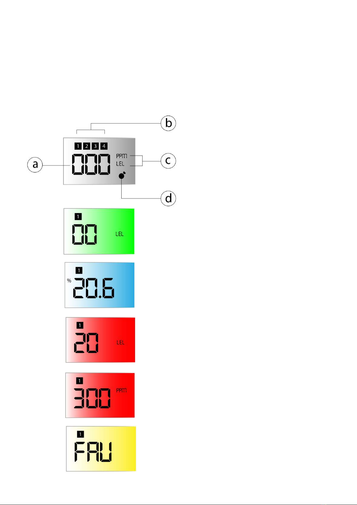
Digital display - Colour change feature in Alarm
Microprocessor control
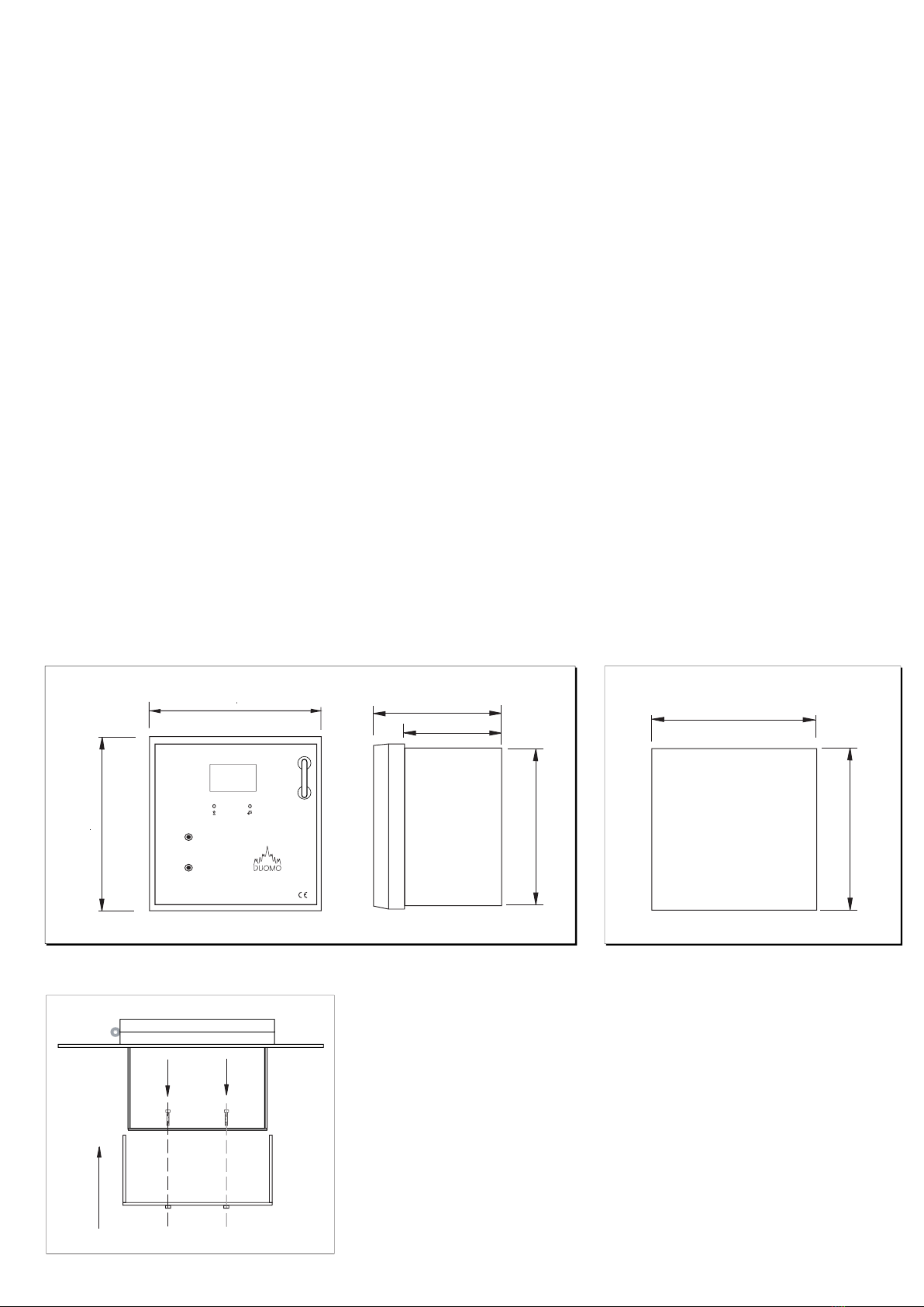
Wall or panel fascia mounted
For up to 4 Sensor
4 - 20mA signal input from each sensor
Measuring range 0 - 20% LEL / 0 - 300ppm
NEW - Oxygen Depletion or excess monitoring
IP44 protective rating
CE Certified and approved to EN50194 for explosive
gases and EN50291 for toxic gases
2 year Warranty - extendable to 3 years by registering
this product on-line www.duomo.co.uk
Features
The BX444-M is a wall or panel mounted microprocessor
based gas detector control unit. It can be configured to
meet customer requirements. The following parameters
can be changed using on board DIP switches:
Number of sensors from 1 to 4
Type of gas to be sensed (explosive or toxic)
Display type, either LEL or ppm
Intrinsic safety option (on or off)
Main alarm relay action (latching or auto-reset)
Oxygen Depletion or Excess monitoring
Application
Duomo is recognised within the gas industry for
providing a comprehensive range of low cost, high
reliability gas detection for many applications. Duomo
Gas detectors are installed in locations such as boiler
rooms, kitchens, car parks, aircraft hangers,
factories and shopping centres. The BX444-M is the
command centre for the complete range of Duomo
gas sensors. All Duomo products are manufactured
to meet relevant European Normatives and proposals
for explosive and toxic gases. EN50194 EN50291
EN50270 EN 61010-1 and designed to be installed to
EN60079-29-2.
Operation
When any connected sensor detects the presence of
the targetgasa4-20mA signal is sent to the
detector, proportional to the level of gas. The
BX444-M then operates a pre-alarm relay - used for
remote sirens or visual indicators. If the level of gas
continues to rise then the second pre-alarm is
actuated. In the case of explosive gases, when the
level of gas reaches 20% LEL, the main alarm relay is
activated to break the electrical supply to the gas
safety shut-off valve (SSOV). The BX444-M also has a
separate volt-free sensor fault relay that actuates if the
correct return signal is not sensed by the detector. The
BX444-M can be configured to detect explosive or toxic
gases. The backlit colour display scrolls through each
sensor and reports their individual status.
CAUTION!
Carefully read the following instructions prior to
installation of this device. Always keep this pamphlet for
future reference. Ensure that the gas detection system is
wired correctly and is only used for the purpose for
which it is intended.
BX444-Mc Gas Detector
i
w: www.duomo.co.uk - e: [email protected].uk - t: 01905 797989 - f: 01905 774296 | © Duomo (UK) Ltd. 2016
Installation and User Guide Rev.01.
The New BX444Mc has a TEST timer function for use by
service and commissioning engineers only. The
controller has a built in sensor test delay that permits the
main alarm relay - in a typical installation operates the
gas valve - to remain on during the alarm phase of a gas
test. This is a great feature in situations where shutting
down the gas supply to boiler plant and other
appliances is not desirable. For more information call the
Duomo technical department on 01905 797989.

230V AC 50Hz +/- 10%
12V DC +/- 10% Max 2.2Ah
Controlled
9.3W maximum @ 230V supply voltage
5W maximum @ 12VDC.
10A resistive 250VAC, 5A 30VDC Resistive
8% LEL / 120ppm CO
13% LEL / 200ppm CO
Fixed at 20% LEL / 300ppm CO
Short circuit, interruption, sensor deterioration
1-4 - Configurable by dip switch.
4 - 20mA on 220 ohm.
1% FS
<2"
Microprocessor
-10 °C to 60 °C
90 seconds
All Duomo Sensors e.g. SG500, SGM595, CO100A, CO200A, SG810
100m
1mm2 CSA (Screened and earthed one end if run with power cables).
144mm x 144mm x 110mm
IP44
EN 50270
2 years from date of manufacture extendable to 3 years by registering
this product online at www.duomo.co.uk
w: www.duomo.co.uk - e: [email protected].uk - t: 01905 797989 - f: 01905 774296 | © Duomo (UK) Ltd. 2016
Technical Specification
Power Supply
Secondary Battery
Battery Charger max 2.2Ah
Power consumption
Power Consumption
Relay contact range
Pre-alarm No. 1
Pre-alarm No. 2
General alarm
Sensor fault
No. of remote sensors
Input signal
Device precision
Reaction time
Control Unit
Working temperature
Start-up self diagnostic delay
Suitable for use with sensor type
Maximum distance for sensor connection
Cable diameter for sensors
Dimensions
Protective rating
Electromagnetic compatibility CE Ref. Norms
Guarantee
Cutout Dimensions (mm)
141
141
108
140
77
14444
14444
BX444MC
TEST
RESET
MAIN
ALARM
2nd
Alarm
FAULT
LEL
ppm
1st
Alarm
SENSORS
OVER LOAD
BATTERY
OVER LOAD
SERVICE
REQUIRED
ON
Fascia mounting the BX444-Mc in a control panel
Mounting Bracket
Overall Dimensions (mm)

BX444-Mc Fascia & PCB Layout
w: www.duomo.co.uk - e: [email protected].uk - t: 01905 797989 - f: 01905 774296 © Duomo (UK) Ltd. 2016
1. Power On - Lights when supply voltage is applied. This light flashes during self-diagnostics start up.
2. Service Required - This light flashes when the the scheduled service is required. This can period be set to
either 6 months or 1 year and is determined by risk assessment.
3. Sensors Overload - When lit indicates a short circuit or overload on the sensor circuitry.
4. Battery Overload - When lit indicates incorrect batter connection or high consumption during charging phase.
5. Test - When pressed checks the sequence and function of the BX444-Mc (See also sensor test timer)
6. Reset - Press this to reset the detector after an alarm or sensor fault condition.(See also sensor test timer)
7. LCD Display - Represents the connected sensors. Each connected sensor reading scrolls automatically. Also
displays the alarm condition and status of each sensor and the BX444mC status; e.g. Test or Fault.
8. 1st Pre-Alarm - At 8% LEL concentration of gas detected. this light is lit and Pre-alarm relay 1 actuated. This relay
output de-energises as the level of detected gas exceeds 13% LEL (Natural Gas) or 200ppm (CO).
9. 2nd Pre-Alarm - At 13% LEL or 200ppm CO detected. Pre-alarm relay 2 actuated.
10. Main Alarm - 20% LEL concentration of gas detected. Main alarm relay actuated.
11. Fault - Indicates a short circuit, sensor fault, loss of signal or incorrect connection of the sensor.In case of a sensor
failure the LED will flash when the relevant sensor is scanned.
12. LEL Explosive - lights when the internal DIP switch (CO/GAS) for a sensor is moved to the GAS position . As the
sensor value is displayed the corresponding light for that sensor is lit.
13. Toxic Gas - This lights when the internal DIP switch (CO/GAS) for a sensor is moved to the CO position. As the
sensor value is displayed the corresponding light for that sensor is lit.
14. Electrical Supply and relay connection terminal plug.
15. Sensor Switches - These are used to turn the sensor on/off, determine the type of gas to be sensed,
16. Select or deselect Oxygen mode
17. Switch for setting latching or non latching in Main alarm condition
18. Continuous or a single pulse alarm relay actuation
19. Positive safety switch.
20. Emergency Stop connection terminal. (remove link when E.Stop is fitted).
21. Sensor and battery (if fitted) connection terminal.
Key

Description of display
a) The displayed number corresponds to the concentration of detected target gas. This is updated
every 4 seconds.
b) The number of the sensor for the displayed value. These scroll continuously through enabled
sensor channels.
c) This indicates whether the sensor is toxic (ppm) or explosive (LEL)
d) The Timer symbol indicates when the BX444Mc is in warm up phase as the sensor counts down to
full operation mode.
The Green display shows an absence of leakage of gas.
This indicates a no gas 'normal' condition.
The Blue display shows percentage of Oxygen. This
display shows a 'normal' condition.
The Red display shows an alarm condition where
alarm Explosive gas threshold have been reached
or passed.
The Red display shows an alarm condition where
alarm Toxic gas threshold have been reached or
passed.
The Yellow display shows an alarm condition
where a a sensor fault exists on one or more
sensors
w: www.duomo.co.uk - e: [email protected].uk - t: 01905 797989 - f: 01905 774296 | © Duomo (UK) Ltd. 2016

Typical Wiring Schematic for BX444-Mc
Installing A Sensor
Electrical Installation
The BX444-Mc is a safety device designed to give audible
alarms and automatically provide latched electrical
isolation of associated gas safety shut off valves in the event of
a gas leak or build up of toxic gases. The sensors can be
located up to 100m from the gas detector. Cable size should
be 1mm2 CSA. If the sensor cables are run separately in
specific conduit it is not essential to use screened cable but
if the cables are routed through conduit or trunking
containing other wiring the use of screened cable is advisable.
The wiring should be performed by a qualified person in
accordance with current regulations. The plug-in terminal rail
makes installation easy and quick. Do not mount close to any
heat source or in an area where moisture is likely to effect
operation. The IP rating of this unit is IP44. Sensors should
be positioned as shown below. If you require any guidance
on this please call Duomo technical support on 01905
797989.
The sensors must be mounted as shown below with
the sintered head pointing vertically down. When
replacing sensors never seperate a sensing head from
its PCB. The sensor will have been calibrated using
this particular board and therefore will not function
correctly with any other.
Important Notes
Always check the wiring before powering up the
system.
Do not test this sensor with anything other than
Duomo test gas (see 'BX444-Mc Operation'
section for further information). Concentrations
above this will damage the sensor and shorten
sensor life. The installation of this gas detector does
not release the user from observing all the
regulations concerning the characteristics,
installation and and the use of gas appliances; the
ventilation of the environment and the
elimination of combustion products in
accordance with the local recommendations,
regulations and bylaws. For any damage caused to
people, property or animals resulting from incorrect
connection, installation or application of this gas
detector Duomo will not be held responsible or liable.
To ensure correct function after installation Duomo
provide a commissioning service using calibrated test
gases. For this service call 01905 797989.
SGM595
autosetting
ON
SGM595
autosetting
ON
SGM595
autosetting
ON
300
1600
300
Natural Gas
Carbon
Monoxide
L.P.G.
w: www.duomo.co.uk - e: [email protected].uk - t: 01905 797989 - f: 01905 774296 | © Duomo (UK) Ltd. 2016

Configuring The BX444-Mc
The BX444-Mc has two DIP switches on the PCB. The left switch is used to control the sensor connected to the system.
The right switch is used to configure the controller itself.
The BX444-Mc can be configured to provide several modes of operation.The configurable parameters
are:
Switch 1 on any of the 1st 4 double DIP switches
Zone ON or OFF - The BX444-Mc will not look for a sensor on a given zone if
the switch is moved to the OFF position. It is not necessary to remove the
return cable from the sensor.
Example shows Zone 1 On, Zone 2 On, Zone 3 Off, Zone 4 On
Switch 2 on any of the 1st 4 DIP switches
Type of gas to be sensed. These are labelled as GAS or CO. The symbols on
the front fascia of the detector are EN standard symbols and refer to any
explosive or toxic gas. If toxic gas, e.g. carbon monoxide is to be sensed on
a given zone move the switch to the CO position. If explosive, e.g. natural
gas, LPG, hydrogen etc. move the switch to the GAS position.
Example shows Zone 1 Explosive, Zone 2 Toxic, Zone 3 Explosive,
Zone 4 Explosive
Switch 1 on 2nd DIP switch set
Positive safety determines the condition of the main alarm relay and
hence the operation of the gas valve. When it is 'ON' the relay is in a
normally open state. When it is 'OFF' the relay is in a normally closed state.
NOTE: This affects how the gas valve operates and means that you may
need to change how it is wired to the BX444-Mc.
Example shows Positive Safety on
Switch 2 on 2nd DIP switch set
Main Alarm relay actuation method. This can be configured to provide
either a latching or a temporary alarm operation. When the main alarm is
actuated in an alarm condition if the switch is in the 'C' position the relay
will remain in this position even after the concentration of gas has
reduced below the alarm threshold. If the switch is in the 'I' position the
main alarm relay will actuate for 60 seconds and then if the level of gas has
dropped will return to the volt-free main alarm relay to the running
condition.The indication on the panel fascia and the audible alarm will still
indicate main alarm. This mode of operation is used when using manual
reset gas valves and battery back-up systems for extending standby
battery life.
Example shows detector configured for a latching main alarm
w: www.duomo.co.uk - e: [email protected].uk - t: 01905 797989 - f: 01905 774296 | © Duomo (UK) Ltd. 2016
Gas Sensed
MainAlarm relay
Reset Pressed
Time
Main alarm switch in 'C' position
Gas Sensed
MainAlarm relay
Reset Pressed
1 minute
Main alarm switch in 'I' position

BX444-Mc Operation
Before powering up the BX444-Mc once again check that all electrical connections are
correct.
1. Apply 230V supply to the Ph and N terminals.Ensure that the correct fuse is used in the supply. (3 or 5A max.)
2. All of the lights on the fascia will light up in turn.This will take approximately 20 seconds.This checks the function of all
the LED's.
3. The ON LED will remain flashing for about 2 minutes. This is the sensor warm-up period. The gas detector will not
provide gas detection during this period.When the ON light becomes constant the detector is in operation.
4. By pushing and maintaining pressure on the manual TEST button a function test can be performed for all pre-alarm
relays and main alarm relay, together with LED's and audible alarm.
The sequence will be:
a) The 8% LEL / 120ppm and Pre-Alarm no. 1 LED will be actuated. The Pre-Alarm relay no.1 will be changed over and
terminals 6 and 7 will be connected.
b) The 13% LEL / 200ppm and Pre-Alarm no. 2 LED will be actuated. The Pre-Alarm relay no. 2 will be changed over and
terminals 8 and 9 will be connected and the audible alarm will continue to sound.
c) The 20% LEL / 300ppm and Main Alarm LED will be actuated.The Main Alarm relay will be changed over and terminals
10 and 11 will be connected, connection between terminals 10 and 12 will be broken and the audible alarm will continue
to sound. (When 'Intrinsic Safety' is on, terminals 10 and 11 will be broken and 10 and 12 will be connected).The relevant
Alarm LED's will light to show which zones are in alarm.
By releasing the the manual TEST button the lights will go out and the audible alarm will cease. If a latched alarm
function on the main relay is configured this will remain on until the RESET button is pressed.
5. In order to conduct a full function test it is essential to use Duomo or equivalent calibrated test gas. The maximum
concentrations are;
- 40% LEL for methane in air
- 350ppm for carbon monoxide
- 0.85% (MOL) for propane
Any higher than this can reduce sensor life. NOTE: NEVER TEST USING NEAT GAS.THIS WILL POISON THE SENSOR.
6. To simulate a sensor fault situation disconnect the sensor plug. The detector will go into a FAULT alarm and the sensor
fault relay will be actuated. This will close the contacts between terminals 4 and 5 and open the contacts between
terminals 10 and 12 (Main Alarm relay).When the plug is reconnected the detector can be reset.
w: www.duomo.co.uk - e: [email protected].uk - t: 01905 797989 - f: 01905 774296 | © Duomo (UK) Ltd. 2016
Switch 3 on 2nd DIP switch set
Determines whether the audible alarm remains operational after levels
have dropped. In memory mode, the alarm remains and will need to be
manually reset. In non-memory mode, the alarm will automatically reset
after levels have dropped.
Example shows memory on
Switch 4 on 2nd DIP switch set
With switch 4 in the on position the BX444Mc is configured to indicate
oxygen levels. The function is determined by setting either excess oxygen
or oxygen depletion on the sensor itself (Duomo SGF104).
IMPORTANT NOTE.
If Oxygen setting is selected it is not possible to connect any other types of
sensors for any other gases. For example natural Gas or CO

Troubleshooting
If you are experiencing difficulties, having made the checks listed above call Duomo on 01905 797989 for
technical assistance.
The Problem The Solution
No lights are illuminated on the fascia of the detector Check that the electrical supply is reaching the
device and that the plug in terminal rail is pushed
into place.
One or all of the sensor fault lights are illuminated
Sensor fault continues to alarm
The detector is subject to repeated alarms
The detector is in a main alarm condition and the
main gas valve is not closing
There is no supply to the solenoid valve
Check that the plug is inserted correctlty.
Check that the sensor wiring is correctly terminated
at both the sensor and detector. Check that 12V DC
is present at the sensor.The green light on the sensor
should be illuminated. Pressing the TEST button it is
possible to check the efficiency of the device and if
the sensors have been connected correctly.
Check that the connections are correct and that
power is supplied to the valve i.e. the valve is not
stuck in the open position. The function of the alarm
relays both Pre-Alarm and Main Alarm can be
checked by pressing the TEST button on the detector
fascia. Check that the main alarm action is configured
for a latching alarm (Switch 2 on 5th DIP switch).
Check the sensor wiring. If the red Overload LED is lit
a short circuit or overload has occurred on the sensor
or the connecting cable.
Ensure that there is not an occassional gas leak. This
may be due to a valve or joint which leaks under
pressure.
The Main Alarm relay is a volt-free contact, therefore
you must connect the live supply to the common of
the main alarm relay contacts terminal 10. A supply
wil then come from terminal 12 to the solenoid valve.
Sensor is connected, but no LED is lit on the front
fascia
Check that the DIP switch is set to the ON position
w: www.duomo.co.uk - e: [email protected].uk - t: 01905 797989 - f: 01905 774296 | © Duomo (UK) Ltd. 2016
In case of alarm
Extinguish any naked flames.
Do not switch lights or electrical devices on or off.
Open all windows and doors to increase ventilation.
If the 'ALARM' LED is off the levels of gas have dropped. A responsible, qualified person is now safe to find the cause of
the alarm.
If the alarm sound remains constant, and the cause is not evident or possible to eliminate turn off the emergency
isolation valves to the area and contact your gas provider emergency line.They will advice accordingly.

Commissioning
It is strongly recommended that this detector should be commissioned by Duomo Commissioning
Engineers or engineers approved by Duomo to carry out this work. A quotation for commissioning or service will
be provided upon request. Fax site details and preferred date for commissioning to 01905 774296 and the Duomo
Service Department will fax back confirmation.
The benefits of this equipment being commissioned by Duomo are:
On board spares. If for whatever reason this equipment doesn't function correctly Duomo engineers will have spares
on board to ensure that the commissioning is successful.
A Duomo Commissioning Certificate is provided.
It is prudent to make electrical connection to the detector terminal plus when withdrawn and leave the plug off
the detector so that the Duomo Engineer is the first to power up the unit on site. This allows wiring to be checked
prior to commissioning and avoids damage due to incorrect connection. Guarantees for this product will become void
if damage is caused by the installer.
w: www.duomo.co.uk - e: [email protected].uk - t: 01905 797989 - f: 01905 774296 | © Duomo (UK) Ltd. 2016
Maintenance
This detector must be function checked as described above using calibrated test gas every 6 months. To arrange for
a Duomo engineer to conduct this work or to arrange a service contract please call 01905 797989.
Other manuals for BX444-Mc
1
Table of contents
Other Duomo Gas Detector manuals