New Focus Vidia-Discrete 64 7 Series User manual

Artisan Technology Group is your source for quality
new and certied-used/pre-owned equipment
• FAST SHIPPING AND
DELIVERY
• TENS OF THOUSANDS OF
IN-STOCK ITEMS
• EQUIPMENT DEMOS
• HUNDREDS OF
MANUFACTURERS
SUPPORTED
• LEASING/MONTHLY
RENTALS
• ITAR CERTIFIED
SECURE ASSET SOLUTIONS
SERVICE CENTER REPAIRS
Experienced engineers and technicians on staff
at our full-service, in-house repair center
WE BUY USED EQUIPMENT
Sell your excess, underutilized, and idle used equipment
We also offer credit for buy-backs and trade-ins
www.artisantg.com/WeBuyEquipment
REMOTE INSPECTION
Remotely inspect equipment before purchasing with
our interactive website at www.instraview.com
LOOKING FOR MORE INFORMATION?
Visit us on the web at www.artisantg.com for more
information on price quotations, drivers, technical
specications, manuals, and documentation
Contact us: (888) 88-SOURCE | sales@artisantg.com | www.artisantg.com
SM
View
Instra
USER’S GUIDE
Vidia-Discrete
External-Cavity Tunable Diode Lasers
Model Series 64X7
U.S. Patent #5,319,668 & Other Patents Pending
Use of controls or adjustments, or performance of procedures
other than those specified herein, may result in hazardous
radiation exposure.
5215 Hellyer Ave. • San Jose, CA 95138-1001 • USA
phone: (408) 284–6808 • fax: (408) 284–4824
e-mail: contact@newfocus.com • www.newfocus.com
™
64X7 rev E.fm Page 1 Tuesday, April 3, 2001 4:16 PM
Artisan Technology Group - Quality Instrumentation ... Guaranteed | (888) 88-SOURCE | www.artisantg.com

Warranty
New Focus, Inc. guarantees its lasers to be free of material and workmanship defects for one year
from the date of shipment. This warranty is in lieu of all other guarantees expressed or implied and
does not cover incidental or consequential loss.
Products described in this document are covered by U.S. Patent #5,319,668 and patents pending.
Information in this document is subject to change without notice.
Copyright 2001, 2000, 1999, New Focus, Inc. All rights reserved.
The symbol and NEW FOCUS, Inc. are registered trademarks and Vidia and Vidia-
Discrete are trademarks of New Focus, Inc. Littelfuse and Slo-Blo are registered trademarks of
Littelfuse, Inc.
Document Number 640054 Rev. E
64X7 rev E.fm Page 2 Tuesday, April 3, 2001 4:16 PM
Artisan Technology Group - Quality Instrumentation ... Guaranteed | (888) 88-SOURCE | www.artisantg.com

Vidia-Discrete Contents • 3
Contents
User Safety 5
Introduction . . . . . . . . . . . . . . . . . . . . . . . . . . . . . . . . . . . . . . 5
Laser Safety . . . . . . . . . . . . . . . . . . . . . . . . . . . . . . . . . . . . . . . 5
Using the Safety Interlock . . . . . . . . . . . . . . . . . . . . . . . . . 7
Getting Started 9
Introduction . . . . . . . . . . . . . . . . . . . . . . . . . . . . . . . . . . . . . . 9
Unpacking the System. . . . . . . . . . . . . . . . . . . . . . . . . . . . . 9
Setting Up the Laser . . . . . . . . . . . . . . . . . . . . . . . . . . . . . . . 9
Starting the Laser for the First Time . . . . . . . . . . . . . . .10
General Operation 13
Overview . . . . . . . . . . . . . . . . . . . . . . . . . . . . . . . . . . . . . . . . 13
What’s Inside . . . . . . . . . . . . . . . . . . . . . . . . . . . . . . . . . . . . 13
Using the Front-Panel Controls . . . . . . . . . . . . . . . . . . .14
Control Combinations . . . . . . . . . . . . . . . . . . . . . . . . . . . 17
Back Panel and Laser-Cavity Connections. . . . . . . . . .17
Turning on the Power . . . . . . . . . . . . . . . . . . . . . . . . . . . .18
Enabling Local (Front-Panel) Control . . . . . . . . . . . . . .19
Setting the Laser Power . . . . . . . . . . . . . . . . . . . . . . . . . . . 20
Setting the Laser Wavelength (Track Mode) . . . . . . . .20
Performing Wavelength Scans . . . . . . . . . . . . . . . . . . . .20
Monitoring Scans . . . . . . . . . . . . . . . . . . . . . . . . . . . . . . . . 22
Modulating the Laser Output . . . . . . . . . . . . . . . . . . . . . 22
Reading an Input Signal . . . . . . . . . . . . . . . . . . . . . . . . . . 23
64X7 rev E.fm Page 3 Tuesday, April 3, 2001 4:16 PM
Artisan Technology Group - Quality Instrumentation ... Guaranteed | (888) 88-SOURCE | www.artisantg.com
4 • Contents NEW FOCUS, Inc.
Computer Control 25
Introduction . . . . . . . . . . . . . . . . . . . . . . . . . . . . . . . . . . . . . 25
Using the IEEE-488 Interface . . . . . . . . . . . . . . . . . . . . . .25
Using the RS-232 Interface. . . . . . . . . . . . . . . . . . . . . . . . 26
Restoring Local (Front-Panel) Control . . . . . . . . . . . . .27
Understanding the Command Types . . . . . . . . . . . . . .27
Programming for the 64X7 Series Laser. . . . . . . . . . . .28
Conventions . . . . . . . . . . . . . . . . . . . . . . . . . . . . . . . . . . . . . 29
Command Summary . . . . . . . . . . . . . . . . . . . . . . . . . . . . . 31
Command Definitions. . . . . . . . . . . . . . . . . . . . . . . . . . . . 33
Principles of Operation 49
Overview . . . . . . . . . . . . . . . . . . . . . . . . . . . . . . . . . . . . . . . . 49
General Theory . . . . . . . . . . . . . . . . . . . . . . . . . . . . . . . . . . 49
Changing the AC-Voltage Selection 53
Troubleshooting 57
Front-Panel Controls Won’t Work . . . . . . . . . . . . . . . .57
Computer Control Doesn’t Work . . . . . . . . . . . . . . . . .57
Wavelength Not Set to the Start Wavelength . . . . . .57
Scans Won’t Start . . . . . . . . . . . . . . . . . . . . . . . . . . . . . . . . 58
Power Display Flashes . . . . . . . . . . . . . . . . . . . . . . . . . . . . 58
Error Codes . . . . . . . . . . . . . . . . . . . . . . . . . . . . . . . . . . . . . .58
Calibrating the Laser . . . . . . . . . . . . . . . . . . . . . . . . . . . . .59
Customer Service 61
Service. . . . . . . . . . . . . . . . . . . . . . . . . . . . . . . . . . . . . . . . . . . 61
Technical Support. . . . . . . . . . . . . . . . . . . . . . . . . . . . . . . . 61
Appendices 63
Appendix A: Physical Specifications. . . . . . . . . . . . . . .63
Appendix B: RS-232 Connector Wiring. . . . . . . . . . . .64
Appendix C: Specifications . . . . . . . . . . . . . . . . . . . . . . .65
64X7 rev E.fm Page 4 Tuesday, April 3, 2001 4:16 PM
Artisan Technology Group - Quality Instrumentation ... Guaranteed | (888) 88-SOURCE | www.artisantg.com

Vidia-Discrete Contents • 5
User Safety
Introduction
Your safe and effective use of this product is of utmost importance
to us at New Focus. Please read the following laser safety
information before attempting to operate the laser.
Laser Safety
The laser radiation emitted from this unit may be harmful. Always
follow these precautions:
• Avoid direct exposure to the beam.
• Always wear protective goggles or eyeglasses appropriate for
working with laser light.
• Avoid looking at the beam directly.
• Be aware of and follow the warnings on the safety labels
(examples are shown on page 6).
• To completely shut off electrical power to the unit, turn off the
keyswitch. The
Power
button on the front panel only controls
power to the laser diode; even when power to the diode is off,
power is still supplied to other system components.
• Do not open the laser system. There are no user-serviceable
parts inside the unit.
• Opening the laser cavity may cause exposure to wavelengths
and power outside the specified range shown on page 65. The
64X7 rev E.fm Page 5 Tuesday, April 3, 2001 4:16 PM
Artisan Technology Group - Quality Instrumentation ... Guaranteed | (888) 88-SOURCE | www.artisantg.com

6 • User Safety NEW FOCUS, Inc.
following table shows the maximum wavelength range and the
maximum internal power accessible inside the laser cavity.
Unauthorized opening of the laser will void the warranty and may result in
burns, electric shock, misalignment of the laser cavity and/or irreparable
damage to the internal components.
Label Identification
The following figures show the locations of the various warning labels
used with this product. Please be aware of them and use caution when
working with the laser.
Figure 1:
Safety labels on the
front of the laser
Model Wavelength Range Max. Power
6427 1450–1650 nm 55 mW
6437 1450–1650 nm 55 mW
Danger label
Addressed
Remote
Laser Power
AC Power
0
1
Local Wavelength
Adjust
Track
Wavelength (nm) Current (nA)
Laser Output
FC/APC
Power
Adjust
Power Setpoint (dBm)
64X7 Made in USA
Tunable Laser Source
VIDIA™-DISCRETE
INVISIBLE LASER RADIATION AVOID
DIRECT EXPOSURE TO BEAM
Power output
Wavelength
CLASS IIIB LASER PRODUCT
Start
λ
Stop
INVISIBLE LASER RADIATION AVOID
DIRECT EXPOSURE TO BEAM
Power output
Wavelength
CLASS IIIB LASER PRODUCT
AVOID EXPOSURE
INVISIBLE LASER RADIATION
EMITTED FROM
THIS APERTURE
AVOID EXPOSURE
INVISIBLE LASER RADIATION
EMITTED FROM
THIS APERTURE
RS 232
GPIB Step
Hi Res
Aperture label
64X7 rev E.fm Page 6 Tuesday, April 3, 2001 4:16 PM
Artisan Technology Group - Quality Instrumentation ... Guaranteed | (888) 88-SOURCE | www.artisantg.com

Vidia-Discrete User Safety • 7
Figure 2:
Certification label
on the back of the
laser
Using the Safety Interlock
The safety interlock connector on the back of the controller is provided
for external safety systems. The system is shipped with a jumper across
the interlock terminals. Do not remove this jumper unless you are
using the safety interlock feature; the laser will not emit light unless the
interlock circuit is closed. The circuit carries 15-V DC.
Interlock
Laser
Sync
Output Current
Modulation
Input
Detector
Input
IEEE 488
RS232
120Vac
WAR N I N G
For continued protection against fire hazard, replace
only with the same type and rating of fuse.
Input VAC
90 - 120
200 - 250
CAUTION
Risk of electric shock, do not remove
cover. Refer servicing to qualified personnel.
10 - 250 VAC
1.2 - 0.5A, 48-66Hz
Fuse
2.0 A T
1.0 A T
5215 Hellyer Ave. ■San Jose ■ CA 95051-0905
U.S. Patent #5,319,668 and Patents Pending
Model Number:
Serial Number:
Manufactured:
This product conforms to the applicable requirements of
21 CFR 1040.10 and 1040.11 at the date of manufacture.
5215 Hellyer Ave. ■San Jose ■CA 95138-1001
U.S. Patent #5,319,668 and Patents Pending
Model Number:
Serial Number:
Manufactured:
This product conforms to the applicable requirements of
21 CFR 1040.10 and 1040.11 at the date of manufacture.
64X7 rev E.fm Page 7 Tuesday, April 3, 2001 4:16 PM
Artisan Technology Group - Quality Instrumentation ... Guaranteed | (888) 88-SOURCE | www.artisantg.com

8 • User Safety NEW FOCUS, Inc.
64X7 rev E.fm Page 8 Tuesday, April 3, 2001 4:16 PM
Artisan Technology Group - Quality Instrumentation ... Guaranteed | (888) 88-SOURCE | www.artisantg.com
Vidia-Discrete Getting Started • 9
Getting Started
Introduction
This section outlines the basic steps needed to start using your Vidia-
Discrete laser system, including information on unpacking the system
and brief set-up and starting notes. For more detailed information on
how to operate the instrument, refer to the “General Operation”
chapter beginning on page 13.
Unpacking the System
Carefully unpack the laser system. Compare the contents against the
packing slip and inspect them for any signs of damage. If parts are
missing or you notice any signs of damage, such as dented or scratched
covers, or broken knobs, please contact New Focus immediately. Save
the shipping container and packing material for future shipping needs.
Check that the power module on the back of the controller is set to the
AC line voltage appropriate for your work station (see page 51 for
information on checking and changing the voltage).
Setting Up the Laser
The laser is designed to operate in environments from 15–35 ˚C. If the
laser has been in storage at temperatures outside the range of 10–40 ˚C,
allow the laser system at least 4 hours to equalize.
When connecting fiber to the laser, use only FC/APC-connectorized
fiber.
64X7 rev E.fm Page 9 Tuesday, April 3, 2001 4:16 PM
Artisan Technology Group - Quality Instrumentation ... Guaranteed | (888) 88-SOURCE | www.artisantg.com

10 • Getting Started NEW FOCUS, Inc.
The laser is shipped with brackets for mounting the system in a rack
and with rubber feet for using the system on a table top. Use a 1/8"
Allen wrench to add or remove the feet or the brackets.
Starting the Laser for the First Time
The following section takes you through the basic steps of starting up
and shutting down the laser. The controls and functions are described
in more detail in the following chapter.
Figure 3:
Front Panel
1. Make sure the laser aperture is blocked or attached to an opti-
cal fiber that is connected to an appropriate receptacle.
Only
use fiber with FC/APC connectors.
2.
Check the voltage setting:
Check that the power module on
the back of the laser is set for the proper AC line voltage (see
page 51 for information on checking and changing the voltage).
3. Connect the power cord:
Attach the power cord to the laser and
plug it into a wall outlet.
4. Turn on the system:
Turn on the
AC Power
keyswitch (position
“
1
”) to initialize the system: the system ID will appear in the
wavelength display during initialization.
After turning the keyswitch, allow the system a minimum of 45 minutes to
warm up before turning on the laser diode (step 6.) to ensure the system meets
its operating specifications.
Once you turn on the keyswitch and the system initializes (about
30 seconds), you can operate the system remotely through the
Addressed
Remote
Laser Power
AC Power
0
1
Local Wavelength
Adjust
Track
Wavelength (nm) Current (mA)
Laser Output
FC/APC
Power
Adjust
Power Setpoint (dBm)
64X7 Made in USA
AVOID EXPOSURE
INVISIBLE LASER RADIATION
EMITTED FROM
THIS APERTURE
INVISIBLE LASER RADIATION AVOID
DIRECT EXPOSURE TO BEAM
Power output
Wavelength
CLASS IIIB LASER PRODUCT
Start
λ
Stop
RS 232
GPIB Step
Hi Res
Tunable Laser Source
VIDIA™-DISCRETE
Note:
Note:
64X7 rev E.fm Page 10 Tuesday, April 3, 2001 4:16 PM
Artisan Technology Group - Quality Instrumentation ... Guaranteed | (888) 88-SOURCE | www.artisantg.com
Vidia-Discrete Getting Started • 11
IEEE-488 (GPIB) or RS-232 ports. Refer to the “Computer Control”
chapter beginning on page 23 for details.
5. Set the power to minimum:
For safety, turn the
Power Adjust
knob counter-clockwise until it stops to set it to minimum power.
6. Activate the laser:
Push the
Laser Power
button. The button will
flash for approximately 5 seconds before current flows through the
diode and the laser begins to emit light.
Laser radiation emitted from this unit may be harmful. Avoid direct exposure
to the beam.
7. Set the operating power:
Turn the
Power Adjust
knob clockwise
to set the laser’s output power (the units are dBm).
To prevent damage to the laser diode, the factory has limited the maximum
current to the laser diode (the maximum is wavelength dependent). When you
reach maximum power for the current wavelength, the controller will engage
the current limiter and the power display will start to flash.
8. Set the system to track mode:
To manually set the wavelength,
the system needs to be in track mode. A light in the
Track
button
indicates when the system is in track mode. If it is not lit, press the
Track
button to turn it on.
9. Set the Wavelength:
Turn the
Wavelength Adjust
knob to set the
wavelength. This will allow you to tune the laser with a resolution
of 0.01 nm. For 0.001-nm resolution, press the
Hi Res/Step
button
and then turn the knob. (Scanning is discussed on page 20.)
10. Turn the laser off:
To minimize the risk of power surges
damaging the laser diode, push the
Power
button to turn off the
laser when it is not in use (the LED on the button will turn off) and
before shutting down the system. Turn the keyswitch off (position
“
0
”) to shut down the entire system.
To avoid the warm-up period, you may want to leave on the system power.
Note:
Note:
Note:
Note:
64X7 rev E.fm Page 11 Tuesday, April 3, 2001 4:16 PM
Artisan Technology Group - Quality Instrumentation ... Guaranteed | (888) 88-SOURCE | www.artisantg.com

12 • Getting Started NEW FOCUS, Inc.
64X7 rev E.fm Page 12 Tuesday, April 3, 2001 4:16 PM
Artisan Technology Group - Quality Instrumentation ... Guaranteed | (888) 88-SOURCE | www.artisantg.com
Vidia-Discrete General Operation • 13
General Operation
Overview
The Vidia-Discrete laser is a stable, narrow-linewidth source of tunable
light. The laser operates in three modes: track mode, automated step-
scan mode, and interactive step-scan mode. Use it in track mode to
operate it at a set wavelength. In the step-scan modes, the laser dwells
at evenly spaced wavelengths as it scans. The system can be operated
manually, using the front-panel controls, or remotely, using one of the
computer interfaces (see “Computer Control” on page 23).
What’s Inside
The 64X7 Series Vidia-Discrete laser is an external-cavity diode laser
(ECDL) based on the Littman-Metcalf design (see “Principles of
Operation” on page 47).
The system provides high resolution when stepping between
wavelengths. An ultra-low-noise current source controls the laser’s
output power. A temperature-control circuit actively stabilizes the
laser-cavity temperature for optimal performance.
Connecting Fiber to the Laser
Use only FC/APC-connectorized fiber with the Vidia-Discrete. For
lasers purchased with the polarization-maintaining fiber option, the
polarization is aligned parallel to the key on the FC connector. The
laser output comes to the front panel through a fiber with an optical
isolator of 30 dB, preventing optical feedback into the laser cavity.
64X7 rev E.fm Page 13 Tuesday, April 3, 2001 4:16 PM
Artisan Technology Group - Quality Instrumentation ... Guaranteed | (888) 88-SOURCE | www.artisantg.com
14 • General Operation NEW FOCUS, Inc.
Using the Front-Panel Controls
The Vidia-Discrete has two control options, local and remote. In local
mode, the front panel provides control of the laser system. In remote
mode, you control the laser over the computer interface (IEEE-488 or
RS-232). Whenever the Vidia-Discrete receives a command over the
computer interface, it restricts most of the front-panel controls (the
Laser Power
and keyswitch control are always enabled). Press the
Local
button on the front panel to restore front-panel control. For
information on using computer control, see page 23.
The controls on the front panel (Figure 4) allow you to read and set the
laser power, wavelength, start and stop wavelengths for scans, and
computer-interface parameters.
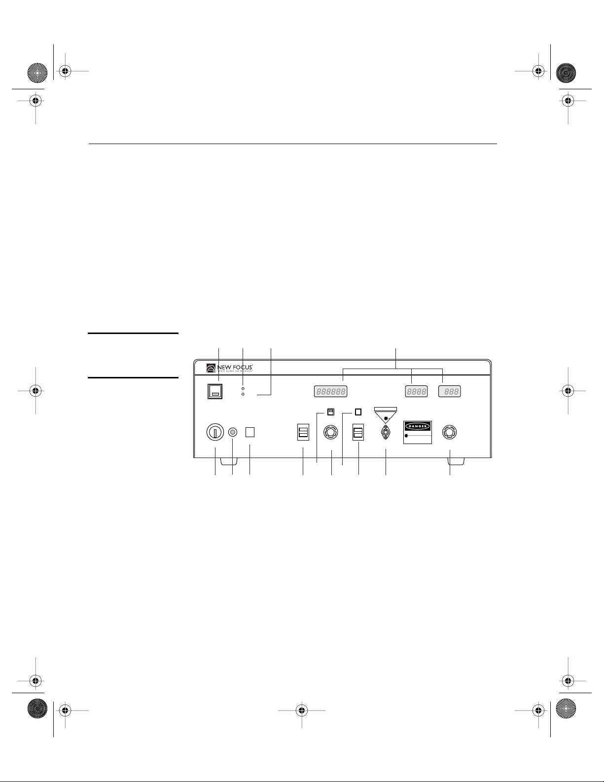
Figure 4:
Controller
front panel
1. AC Power Keyswitch:
Controls AC power to the entire laser sys-
tem, including the temperature-control circuit. Power is not sup-
plied to the laser diode until the
Laser Power
button is activated.
2. Power Indicator:
This indicator is lit when the system power is
on. To check if power is being supplied to the laser diode, check the
indicator light in the
Laser Power
button.
3. Local Button:
Returns the controller to local (front-panel) control
when the driver is in remote (computer-control) mode.
4. Laser Power Button:
Turns on and off current to the laser diode.
When the laser power is on, this button will remain lit.
Addressed
Remote
Laser Power
AC Power
0
1
Local Wavelength
Adjust
Track
Wavelength (nm) Current (mA)
Laser Output
FC/APC
Power
Adjust
Power Setpoint (dBm)
64X7 Made in USA
AVOID EXPOSURE
INVISIBLE LASER RADIATION
EMITTED FROM
THIS APERTURE
INVISIBLE LASER RADIATION AVOID
DIRECT EXPOSURE TO BEAM
Power output
Wavelength
CLASS IIIB LASER PRODUCT
Start
λ
Stop
11312
11
10
9
8
76
3
54
214
RS 232
GPIB Step
Hi Res
Tunable Laser Source
VIDIA™-DISCRETE
64X7 rev E.fm Page 14 Tuesday, April 3, 2001 4:16 PM
Artisan Technology Group - Quality Instrumentation ... Guaranteed | (888) 88-SOURCE | www.artisantg.com

Vidia-Discrete General Operation • 15
5. Addressed Indicator:
This indicator is lit whenever the controller
is communicating over the computer interface (see the “Computer
Control” chapter beginning on page 23).
6. Remote Indicator:
This indicator is lit whenever the controller is
under computer control, via either the IEEE-488 (GPIB) or the RS-
232 interface. (See “Computer Control” on page 23.)
7. Wavelength, Current, and Power Displays:
Show the status of
the different laser parameters, as well as errors and system-
identification information. Units are nm, mA, and dBm,
respectively.
The current changes with the power and wavelength; it is not
adjustable. You can modulate the current through a back-panel
BNC input (see page 21). The display does not reflect any current
modulation.
The power display shows the power setpoint. It will display this
value even if the laser-diode power is off.
8. GPIB/RS232 Switch
: While pressing the
Local
button, hold this
switch up to view the GPIB address in the wavelength display; hold
it down to view the baud rate for RS-232 control. Use the
Wavelength Adjust
knob to adjust the address or baud rate.
9. Track Button:
Switches the laser between track mode, where you
can specify a set operating wavelength, and scan mode.
10. Wavelength Adjust Knob:
Adjusts the wavelength while in track
mode. Sets other parameters when other buttons or switches are
depressed (see “Control Combinations” on page 16).
11. Hi Res/Step Button:
In track mode, press this button to set the
wavelength with 0.001-nm accuracy (the wavelength display will
shift two decimal places).
In scan mode, starts an interactive step scan. Each time you press
the button, the laser will tune to the next step. (Step size can only
be set using computer control. For more on scanning, see page 20.)
12. Start/Stop
λ
Switch
: Display or set the start and stop wavelengths
for wavelength scans.
64X7 rev E.fm Page 15 Tuesday, April 3, 2001 4:16 PM
Artisan Technology Group - Quality Instrumentation ... Guaranteed | (888) 88-SOURCE | www.artisantg.com
16 • General Operation NEW FOCUS, Inc.
13. Laser Output:
Connector for FC/APC-connectorized fiber. Before
turning on the laser power, make sure the laser output is blocked
or attached to an optical fiber and the fiber is connected to an
appropriate receptacle on the other end.
The Vidia-Discrete is available with either single-mode or
polarization maintaining fiber. If you purchased polarization-
maintaining fiber as an option with your laser, the polarization is
aligned parallel to the key on the FC connector.
14. Power Adjust Knob:
Adjusts the laser’s output power.
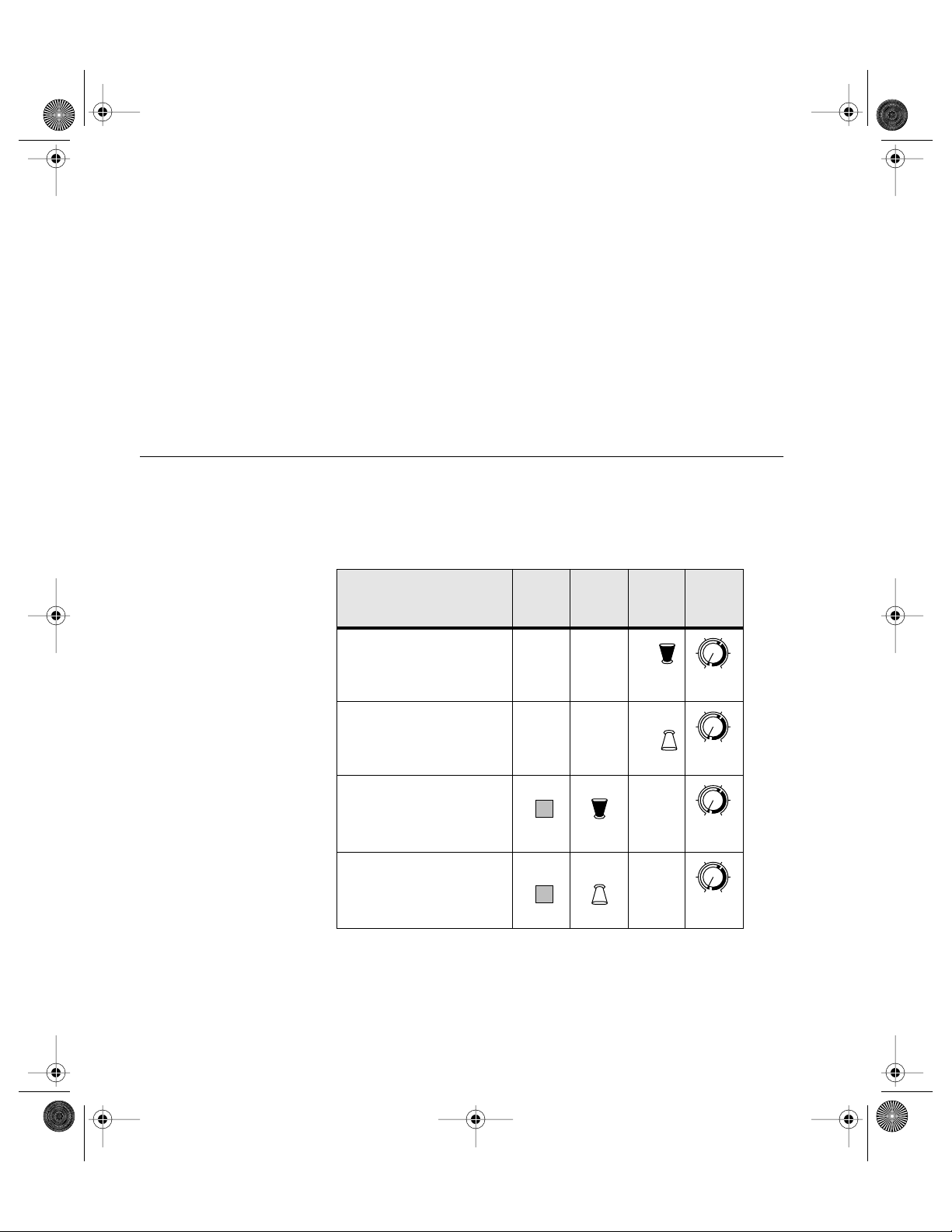
Control Combinations
To access many of the laser’s features from the front panel, you will
need to use several controls at the same time. The following table
summarizes these combinations.
Local
Button
GPIB/
RS232
Switch
Wave-
length
Switch
Wave-
length
Knob
View/Set start
wavelength for scans
View/Set stop
wavelength for scans
Set GPIB address
Set RS-232 baud rate
Start
λ
Stop Wavelength
Adjust
Start
λ
Stop
Wavelength
Adjust
Local
GPIB
RS 232
Wavelength
Adjust
Local
GPIB
RS 232
Wavelength
Adjust
64X7 rev E.fm Page 16 Tuesday, April 3, 2001 4:16 PM
Artisan Technology Group - Quality Instrumentation ... Guaranteed | (888) 88-SOURCE | www.artisantg.com
Vidia-Discrete General Operation • 17
Back Panel and Laser-Cavity Connections.
There are several input and output connectors on the back of the laser
controller.
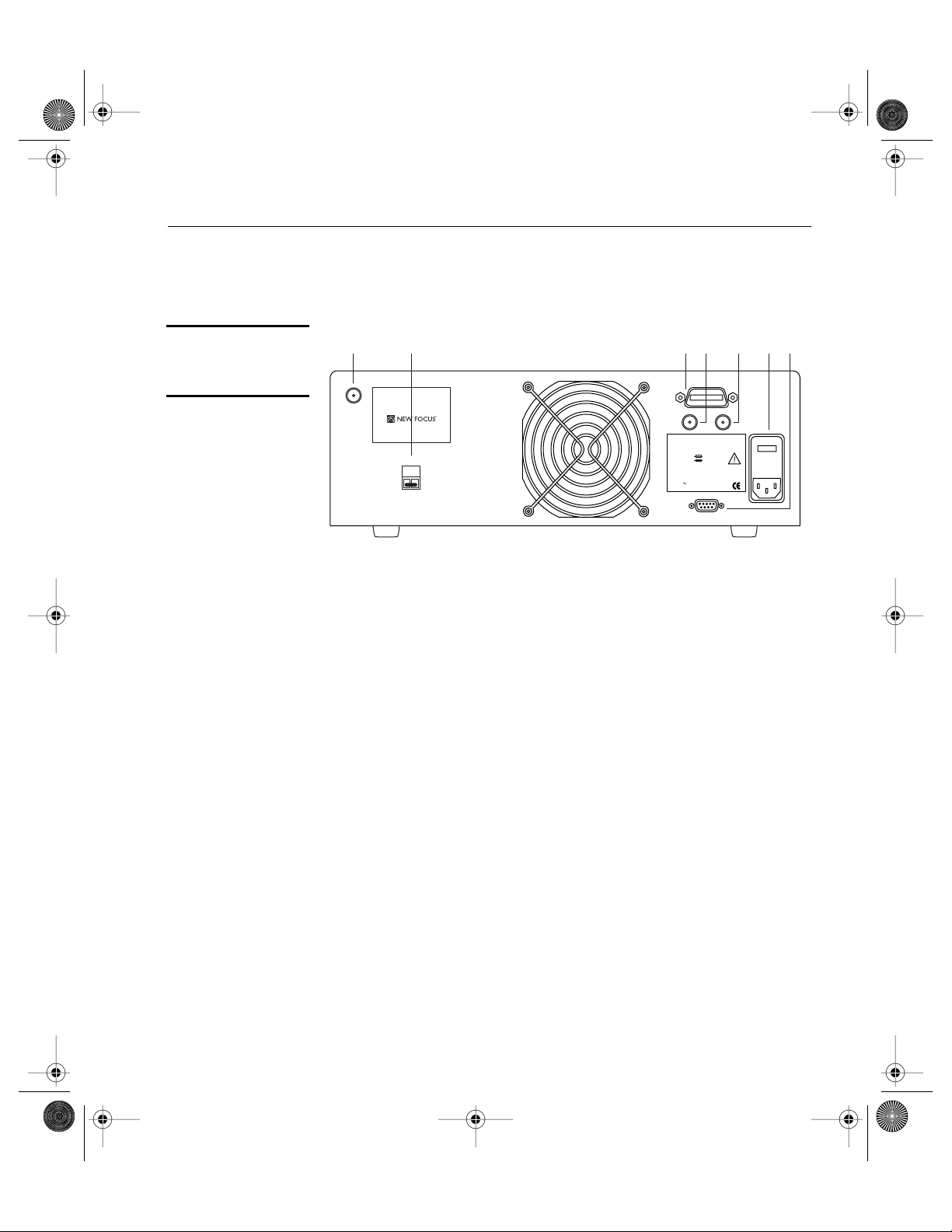
Figure 5:
Controller back
panel
1. Laser Sync Output: This output is used only during the laser
manufacturing process.
2. Interlock: For use with external safety systems, the laser will
not operate if the interlock circuit is open.
3. IEEE 488: Connector for controlling the laser over an IEEE-488
(GPIB) interface.
4. Current Modulation Input: BNC connector for modulating
the laser current (amplitude).
5. Detector Input: BNC connector for monitoring an external
instrument through the laser controller’s computer interface.
6. Power Module: The operating voltage is displayed on the
power module. The module also contains the fuses for the unit.
7. RS232: Connector for controlling the laser over an RS-232
interface.
Interlock
Laser
Sync
Output Current
Modulation
Input
Detector
Input
IEEE 488
RS232
120Vac
WAR N I N G
For continued protection against fire hazard, replace
only with the same type and rating of fuse.
Input VAC
90 - 120
200 - 250
CAUTION
Risk of electric shock, do not remove
cover. Refer servicing to qualified personnel.
10 - 250 VAC
1.2 - 0.5A, 48-66Hz
Fuse
2.0 A T
1.0 A T
Model Number:________________________________
Serial Number:_________________________________
Manufactured:_________________________________
1 543276
5215 Hellyer Ave. ■San Jose ■ CA 95051-0905
U.S. Patent #5,319,668 and Patents Pending
This product conforms to the applicable requirements of
21 CFR 1040.10 and 1040.11 at the date of manufacture.
64X7 rev E.fm Page 17 Tuesday, April 3, 2001 4:16 PM
Artisan Technology Group - Quality Instrumentation ... Guaranteed | (888) 88-SOURCE | www.artisantg.com
18 • General Operation NEW FOCUS, Inc.
Turning on the Power
1. Make sure the laser aperture is blocked or attached to an optical
fiber that is connected to an appropriate receptacle. Use only
FC/APC-connectorized fiber.
2. Before turning on the system for the first time, check that the AC
line voltage indicator on the back of the controller matches the
voltage you are using (see page 51).
3. Turn the power keyswitch on the front panel clockwise (to the “1”
position). The display will show the laser model number and
software revision number.
The keyswitch turns on AC power for the entire laser system,
including the temperature circuit for the laser diode. It does not
turn on the power to the laser diode.
4. Wait at least 45 minutes after turning on the keyswitch to allow the
system to warm up.
5. Press the Laser Power button on the controller front panel to allow
current to flow to the diode. The button will flash during the five -
second safety delay before the current is activated. The button will
remain lit while current is flowing to the laser diode.
6. Turn the Power Adjust knob to control the output power. Turn-
ing the knob clockwise increases power: counter-clockwise
decreases power. If the Power Display begins to flash, the power
is already at maximum for the selected wavelength. See page 65
for power specifications.
Before turning off the system, you should first turn off power to the
laser diode by pressing the Laser Power button.
You can avoid the 45-minute warm-up period by leaving the system power
(keyswitch) on when you are not using the laser.
Note:
Note:
64X7 rev E.fm Page 18 Tuesday, April 3, 2001 4:16 PM
Artisan Technology Group - Quality Instrumentation ... Guaranteed | (888) 88-SOURCE | www.artisantg.com

Vidia-Discrete General Operation • 19
Enabling Local (Front-Panel) Control
When the laser receives a command from the computer interface, it
deactivates all of the front-panel controls except the Laser Power and
Local buttons. This remote-control mode is indicated by the Remote
LED on the front panel. To return the controller to local (front-panel)
control, press the Local button on the front panel.
Setting the Laser Power
Turn the Power Adjust knob to set the power.
To prevent damage to the laser diode, the factory has limited the
maximum current to the laser diode. When you reach maximum
power, the controller will engage the current limiter and the power
display will start to flash.
Maximum power is wavelength dependent. See page 65 for power specifications.
Setting the Laser Wavelength (Track Mode)
The Vidia-Discrete has two modes, track mode and scan mode. While
in track mode, you can actively control the tuning motor to operate the
laser at a set wavelength.
1. If the laser is in scan mode (the LED in the Track button is off),
switch to track mode by pressing the Track button.
You cannot switch to track mode during a scan. Finish the current
scan or use computer control to abort the scan.
2. Standard tuning resolution is 0.01 nm. For 0.001-nm resolution,
press the Hi Res/Step button while in track mode. The wave-
length display will shift two decimal places.
3. Turn the Wavelength Adjust knob to set the wavelength. Turn
the knob clockwise to increase the wavelength: counter-clock-
wise to decrease the wavelength.
Note:
Note:
64X7 rev E.fm Page 19 Tuesday, April 3, 2001 4:16 PM
Artisan Technology Group - Quality Instrumentation ... Guaranteed | (888) 88-SOURCE | www.artisantg.com
This manual suits for next models
2
Table of contents
Other New Focus Measuring Instrument manuals


