New Power S-FLS Series User manual
604100501000902
Website:http://www.anpe.cnAddress:NewPowerindustrialPark,LuheEconomicDevelopmentZone,Nanjing,China
ServiceTel:+86(25)‐84459479Postcode:211500
S-FLS series
Non-Intrinsic Safety Signal
Surge Protective Devices
Nanjing New Power Electric Co., Ltd.
Test standards
IEC 61643-1/GB 18802.1; IEC 61643-21/GB/T 18802.21
IEC 62305-1~IEC 62305-5; IEC 61508-1~IEC 61508-7
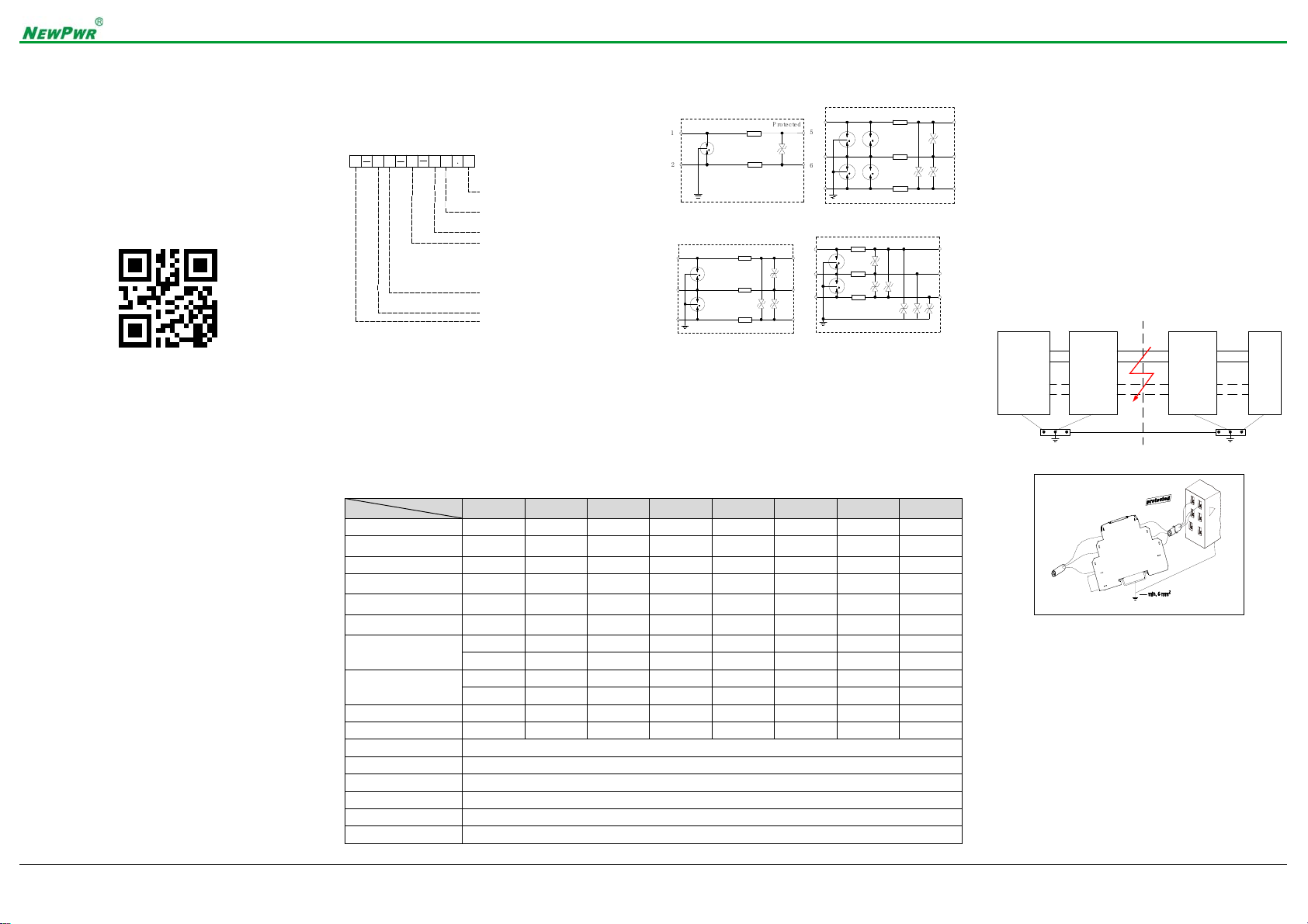
Model description
Features
7.4 mm Ultra-thin design, saving space;
Multiple protection circuit, strong resistance to surge;
Support terminal grounding (optional);
35 mm rail installation;
A variety of models, applicable to all measurement.
Parameters
Wiring diagram
Unprotected P
r
o
t
e
c
t
e
d
1
2
5
6
In Out
S-FLS-2-5, S-FLS-2-24 S-FLS-2-5G, S-FLS-2-24G
1
2
5
6
Unprotected Protected
37
In Out
1
2
5
6
Unprotected Protected
37
In Out
S-FLS-3-5, S-FLS-3-24 S-FLS-3-5G, S-FLS-3-24G
Applications
S-FLS series non-intrinsic safety SPD is used to
protect signals and control equipments, preventing
interference caused by lightning or high voltage switch.
In a short surge impact, by discharging the transient
current to the ground to clamp the voltage in a safe
level and ensure the transmission. It guarantees the
safety for industrial automation equipment.
This product is a 7.4 mm ultra-thin design with the
advantages of strong surge resistance, low residual,
fast response, etc. Moreover, it is easy to use and
install, can support all kinds of control system, the I/O
system, communication network equipment, etc.
Equipotential connection drawing
1
2
3
PE
5
6
7
Connection diagram
Grounding
It is necessary to ground the SPD correctly. Each
SPD should be grounding by DIN rail.
Type
Parameter S-FLS-2-5 S-FLS-2-24 S-FLS-2-5G S-FLS-2-24G S-FLS-3-5 S-FLS-3-5G S-FLS-3-24 S-FLS-3-24G
Voltage Un 5 V 24 V 5 V 24 V 5 V 5 V 24 V 24 V
Max. operating voltage Uc
(DC) 6 V 32 V 6 V 32 V 6 V 6 V 32 V 32 V
nominal current IL600 mA 600 mA 600 mA 600 mA 600 mA 600 mA 600 mA 600 mA
Total discharge current In
(8/20 μs, C2) 10 kA 10 kA 10 kA 10 kA 10 kA 10 kA 10 kA 10 kA
Discharge current per path
In (8/20 μs, C2) 5 kA 5 kA 5 kA 5 kA 5 kA 5 kA 5 kA 5 kA
Impulse current
Iimp (10/350 μs) 2 kA 2 kA 2 kA 2 kA 2 kA 2 kA 2 kA 2 kA
Voltage protection
Up (8/20 μs, C2)
L-L ≤45 V L-L ≤60 V L-L ≤45 V L-L ≤60 V L-L ≤45V L-L ≤45V L-L ≤60V L-L ≤60 V
L-PE ≤650 V L-PE ≤650 V L-PE ≤45 V L-PE ≤60 V L-PE ≤650 V L-PE ≤45V L-PE ≤650 V L-PE ≤60 V
Voltage protection
Up (1 kV/μs, C3)
L-L≤15 V L-L ≤45 V L-L ≤15 V L-L ≤45 V L-L ≤15 V L-L ≤15V L-L ≤45 V L-L ≤45 V
L-PE ≤650 V L-PE ≤650 V L-PE ≤15 V L-PE ≤45 V L-PE ≤650 V L-PE ≤15 V L-PE ≤650 V L-PE ≤45 V
Series impedances 1.8 Ω1.8 Ω1.8 Ω1.8 Ω1.8 Ω1.8 Ω1.8 Ω1.8 Ω
Limiting frequency (fG) 100 MHz 10 MHz 100 MHz 10 MHz 10 MHz 10 MHz 10 MHz 10 MHz
Response time <1 ns
Temperature -40 ℃~ +80 ℃
Installation 35 mm DIN rail
Connections rail grounding/terminal grounding (optional)
Connecting wire size 0.2 ~ 2.5 mm2
Material PC
Field
devices
(transmitter)
S series
surge
protective
devices
S series
surge
protective
devices
Control
room
device
(DCS or
PLC)
Field Control room
XXX XXX
.X
Explosion proof: blank: non-intrinsic safety
Series: S: S series SPD
Types: FL: lightning protection
Structure: T: 12.4 mm module insert
Input channel 2: 2-wire;3: 3-wire
Voltage: 5: 5 V DC; 24: 24 V DC
Protected mode: blank: floating
S: 7.4 mm; P:field installation
4: 4-wire; 2D: dual channel
Ex: intrinsic safety
2S: 2-wire series;3S: 3-wire series
2P: 2-wire parallel;3P: 3-wire parallel
4P: 4-wire parallel
G: grounding
1
2
5
6
Unprotected Protected
37
In Out
604100501000902
Website:http://www.anpe.cnAddress:NewPowerindustrialPark,LuheEconomicDevelopmentZone,Nanjing,China
ServiceTel:+86(25)‐84459479Postcode:211500
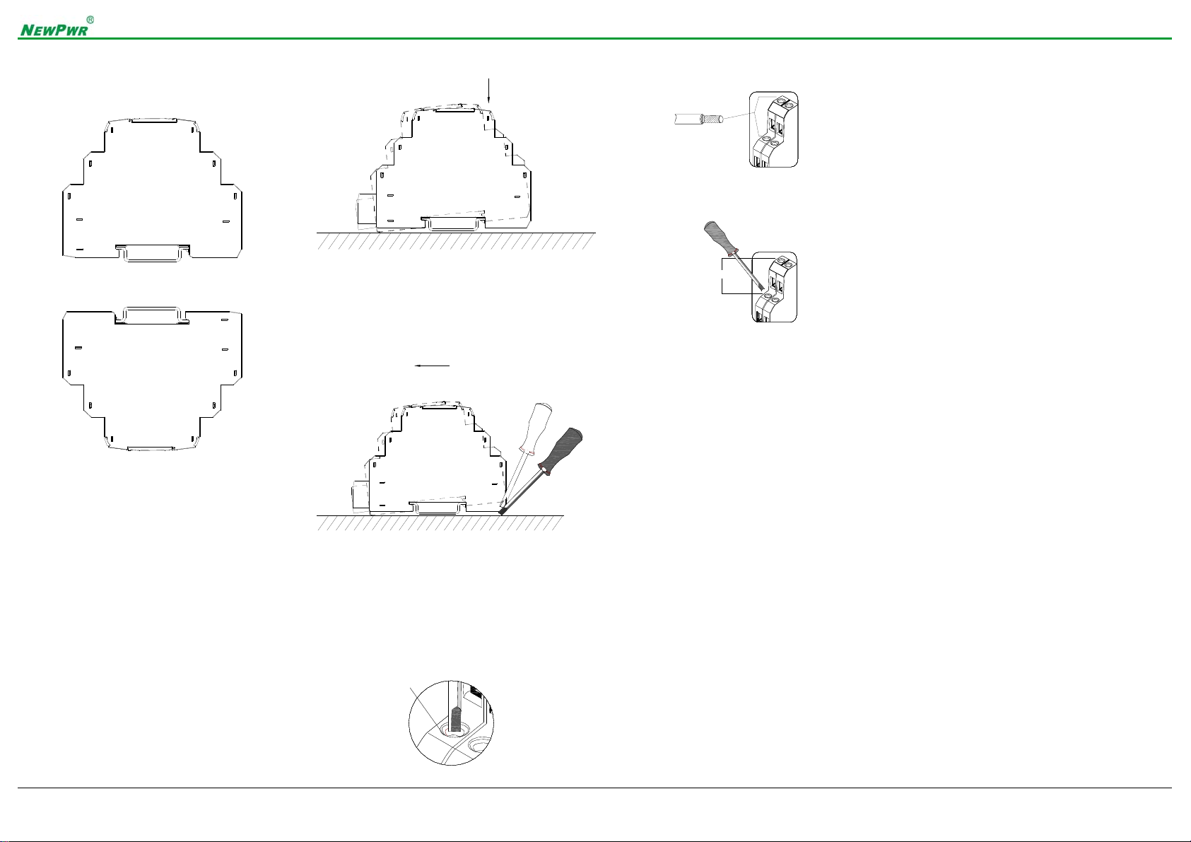
Dimension
Width × Height× Length:7.4 mm × 95.2 mm × 70 mm
Installation
The apparatus can be mounted on a 35 mm standard
rail corresponding to DIN EN 60715, they must be
snapped onto the rail, and never slanted or tipped to
the side.
Requirements for installation
In the safe zone, surge protective devices and safety
barrier can be installed in the same or different cabinet,
but can not be installed on the same track side by
side.
The cables (and wires) associated with the safety and
the hazardous area should be wired and laid
separately.
Installation steps are as follows:
Installation
Make the metal bayonet locked into the guide rail,
push the SPD in the rail as the direction of the arrow
in the above.
Removing steps are as follows:
Removing
First, pry the metal lock off the rail with screwdriver as
arrow shown, pull downward the springs, and rotate
the SPD, then remove it.
Connections
Using M3 screwdriver;
M3
Wire size is 0.2 mm2~2.5 mm2;
2.5 mm2
Maximum torque of the screw is 0.5 N.m;
Max. 0.5 N.m
Attentions
The current Input Isolated Safety Barriers was
constructed in protection degree IP 20 and must
therefore be protected from undesirable ambient
conditions (water, small foreign objects). It is suitable
for installed in control room or high density field
cabinet, convenient for installation and displacement.
The devices were designed for use in pollution degree
2 and overvoltage category III as IEC/EN 60664-1. If
used in areas with higher pollution degree, the devices
need to be protected accordingly.
Installation position shall not be affected by strong
mechanical vibration, impact and electromagnetic
induction from signal terminal and power supply,
should conformity with the requirements on
electromagnetic interference resistance of products in
Class 3 industrial field atmosphere stipulated in IEC
61000-4, and the atmosphere shall be free from
gases that are corrosive to metal and plastic
components.
Before installation, please check the surge protector is
intact or not. If have any damage, it should not be
installed.
Only using the SPD according to this document, if
more than the rated value, SPD and other device are
likely to be damaged.
Devices must only be repaired directly by the
manufacturer. Tampering with the apparatus is
dangerous and therefore forbidden.
Supplements
The apparatus must be installed, connected and
adjusted by qualified personnel in non-hazardous area
according with the instruction manual.
If faults cannot be eliminated, the apparatus must be
taken out of operation and protected from being
placed in service again inadvertently. Devices must
only be repaired directly by the manufacturer.
Tampering with the apparatus is dangerous and
therefore forbidden.
The operator must strictly comply with the relevant
local safety standards and guidelines.
If there is any content difference between the
specification and the website or sample, the
instructions shall prevail. We reserve the rights to
change or update the product information without prior
noticing the users.
This manual suits for next models
8


