Newall M20-TT User manual

N
M20-TT Installation for
Knee Type Milling
Machine

M20 Installation for Knee Type
Milling Machine
Table of Contents
PAGE
Introduction…………………………………………………………………………..1
Warnings……………………………………………………………………………..1
Dimensions…………………………………………………………………………..1
1.0 Installing Longitudinal (X-axis) scale………………………………………2
2.0 Installing Longitudinal (X-axis) reader head………………………………3
3.0 Installing cross travel (Y-axis) scale……………………………………….4
4.0 Installing cross travel (Y-axis) reader head ………………………………5
Standard mounting
5.0 Installing cross travel (Y-Axis) reader head………………………………6
Bridgeport type mounting
6.0 Cable routing………………………………………………………………...6
7.0 Final check…………………………………………………………………...6

INTRODUCTION
It is important that you read and understand this manual prior to beginning the
installation. If you have any questions at any time please contact the Newall
Support Department.
Due to the variety of knee type manual milling machines, it may be necessary
to modify the brackets provided or manufacture custom brackets.
Some manufacturers of milling machines have pre-tapped holes for DRO
systems, you may find that you can use some of these holes.
In order to reduce erroneous readings caused by machine wear, it is
recommended that the scale be fitted as close to the machine lead screw or
axial drive shaft as possible.
WARNINGS
If for any reason the machine axis travel is greater than the actual scale travel
‘mechanical stops’ should be fitted to the machine to avoid damage caused by
over travel. Newall will not accept responsibility for scale and reader head
damage caused by machine over travel.
DIMENSIONS
TRAVEL + 120mm (4.725")
28.00
(1.1")
60.00
(2.362")
SLOTS TO FIT M4 SHCS
INCREMENTAL TRACK STICKER
SCALE
HEA
1
www.newall.com

1.0 INSTALLING LONGITUDINAL (X-AXIS) SCALE – REAR
MOUNTING
1.1 The scale is installed 1
st
, however before installing check that the scale
will be reached by the head once attached to the bracket.
1.2 Fit the scale central on the rear of the table, mark, drill and tap 2 M4 x
20mm deep holes. NB the ‘grating sticker’ should be on the top.
1.3 Loosely fix scale into place using the M4 x 20mm socket cap head
screws (SHCS) provided.
1.4 The scale should be mounted parallel to the machine faces to within
0.1mm(0.004”)/meter. Please see fig below.
1.5 The scale can be adjusted up and down on the slots and in and out via
the grub screws either end of the scale.
1.6 Once parallel tighten up both screws.
1.7 On longer scales side clamps are provided, these can be used on the
top, bottom or both depending on space available.
1.8 Position the side clamp and mark the hole centre.
1.9 Drill and tap M4 x 10mm hole.
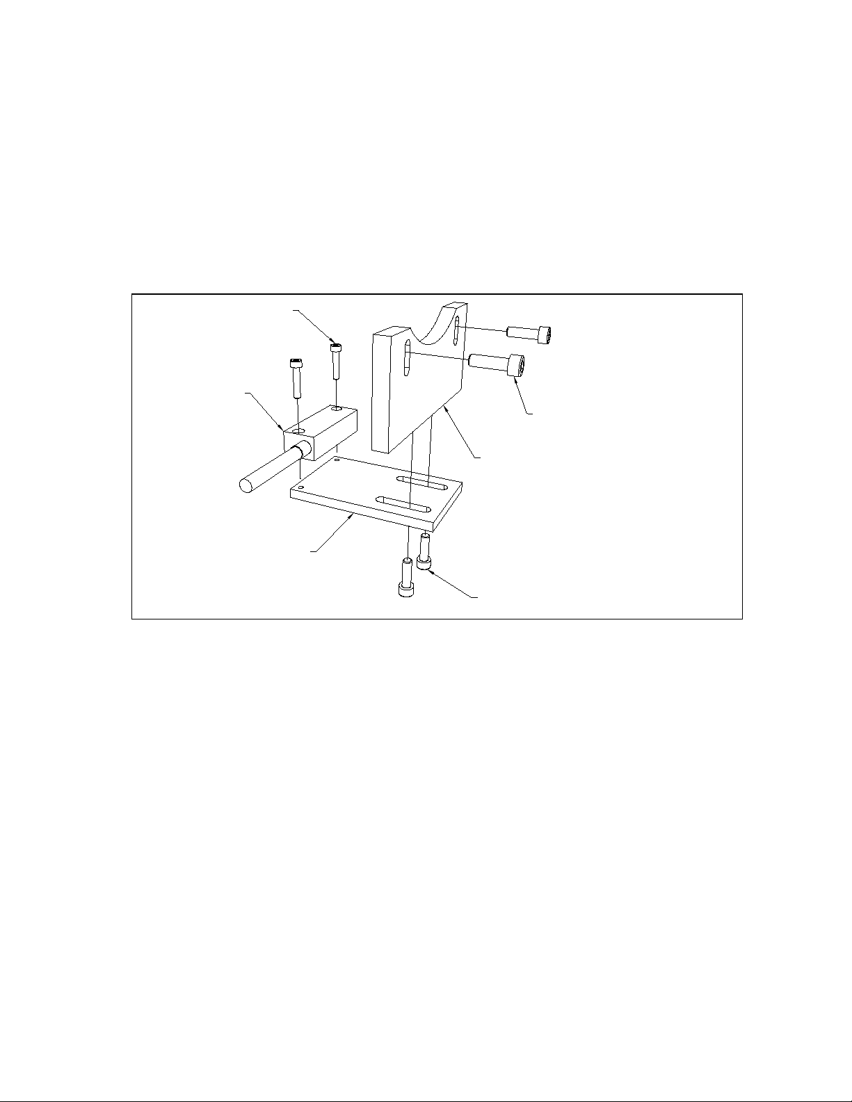
1
www.newall.com
2
www.newall.com
0.1 (0.004")
0.1 (0.004")
SCALE
M4 x 20 SHCS
SI E CLAMP (FOR LONGER SCALES)
(CAN USE AT TOP AN BOTTOM)

1.10 Fix clamp into place using M4 x 10mm SHCS
2.0 INSTALLING LONGITUDINAL (X-AXIS) READER HEAD –
REAR MOUNTING
2.1 Attach the reader head to bracket assembly as shown.
2.2 Drill and tap holes suitable for the screws shown below.
2.3 Fix bracket into place, central on the fixed bed.
2.4 The gap between the reader head and the scale should be 0.5mm ±
0.1mm this is set with the shim provided, align reader head as shown.
The incremental track stickers on the head and scale should
match.
M4 x 20 SHCS
M6 x 35 SHCS
(1/4-20UNC x 1 1/2" SHCS)
HEA
MOUNTING BLOCK
3
www.newall.com

2.5 Adjust the metal wipers as required
2.6 Fit scale cover using the M4 Button head screw (BHSS), see below.
3.0 INSTALLING CROSS TRAVEL (Y-AXIS) SCALE
3.1 Check the travel and determine the best place to fit the scale however
before installing check that the scale will be reached by the head once
attached to the brackets.
3.2 Mark, drill and tap 2 M4 x 20mm deep holes. NB the ‘grating sticker’
should be on the top.
3.3 Repeat steps 1.3 to 1.6.
M4 x 6 BHSS
GUAR
4
www.newall.com

4.0 INSTALLING CROSS TRAVEL (Y-AXIS) READER HEAD –
STANDARD MOUNTING
4.1 Attach the reader head to bracket assembly as shown.
4.2 Drill and tap holes suitable for the screws shown below.
4.3 Fix bracket into place, central on the saddle.
4.4 Repeat steps 2.4 to 2.6
M4 x 20 SHCS
M6 x 20 SHCS
M6 x 20 SHCS
M6 FULL NUT
ANGLE BRACKET
HEA
GUAR
M4 x 6 BHSS
5
www.newall.com

5.0 INSTALLING CROSS TRAVEL (Y-AXIS) READER HEAD –
BRIDGEPORT TYPE MOUNTING
5.1 Attach the reader head to bracket assembly as shown.
5.2 Drill and tap holes suitable for the screws shown below.
5.3 Fix bracket into place, central on the saddle.
5.4 Repeat steps 2.4 to 2.6
6.0 CABLE ROUTING
One of the most important elements of the installation is proper cable
routing. Loose and dangling cables can be snagged or crushed
causing undue damage to the equipment. ‘P’ clips and nylon tie wraps
are provided to secure the cables to the machine.
7.0 FINAL CHECK
PRIOR TO PUTTING THE DRO INTO SERVICE, TRAVERSE THE
TABLE, SADDLE, KNEE AND RAM TO THEIR EXTREME TRAVEL
LIMITS. THIS WILL ENSURE THAT THE SCALE TRAVELS DO NOT
EXCEED THEIR LIMITS AND THAT THE ARMOURED CABLES ARE
NOT STRESSED.
M4 x 20mm SHCS
M6 x 16mm SHCS
M6 x 25mm SHCS
(1/4-20UNC x 1" SHCS)
HEA
MOUNTING PLATE
MOUNTING PLATE
6
www.newall.com

NEWALL MEASUREMENT SYSTEMS LTD
Technology Gateway, Cornwall Road
South Wigston, Leicetser, LE18 4XH
Tel: (0116) 264 2730, Fax: (0116) 264 2731
E-mail: [email protected].uk
NEWALL FRANCE SARL
63 Rue Victor Hugo, F-59200, Tourcoing, France
Tel: 03.20.01.03.13, Fax: 03.20.26.13.41
NEWALL ELECTRONICS INC
1778 Dividend Drive, Columbus, Ohio, 43228, USA
Tel: (1) 614.771.0213, Fax (1) 614.771.0219
E-mail: [email protected]
023-81230/0
Table of contents
Other Newall Power Tools manuals