Newgy Ball Catch Net II Quick setup guide

ATTACH FRONT FRAME TO BRACKET
Line up the hole at
the end of the Right
Front Frame with
the hole on the right side of
the Frame Bracket. Insert a
Hex Screw through the holes
and fasten with a Wing Nut.
The Wing Nut needs to be at
the rear of the Frame Bracket
(as defined in Photo 2).
Repeat on the left side. Do not secure the pop buttons yet.
ARRANGE FRAME PARTS
Arrange the frame parts as shown below. Pieces
are arranged in their relative final positions.
IMPORTANT: The rectangular cutout in the
Frame Bracket should be forward of the central plate of
the Bracket (to ensure proper positioning). You will also
need the 2 Hex Screws, 2 Wing Nuts, a #2 Phillips head
screwdriver, and a pair of pliers. All parts are designated
left or right as if you were standing in front of the net.
BALL CATCH NET II
ASSEMBLY/USE INSTRUCTIONS
VERIFY ALL PARTS
Unpack all the parts from the box. Cover your
ping pong table top and layout the parts so you
can identify them. Become familiar with each part
as shown in this diagram. If uncertain of the identity of a
part, look for a small silver tag with the name of that part.
3
1
2
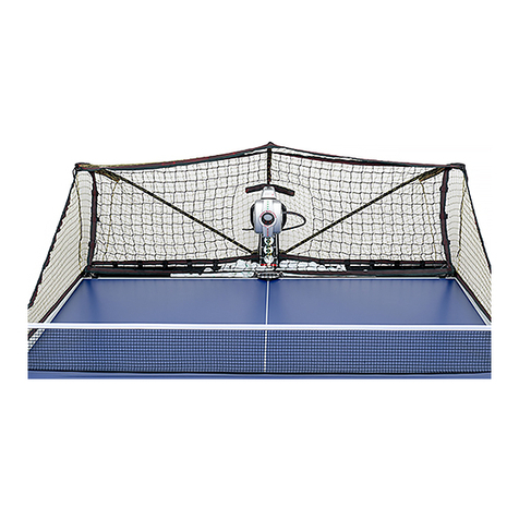
The Newgy Ball Catch Net II extends the functionality of
Newgy Robo-Pong robots that have ball buckets. Placed
behind a robot sitting on the table, it will capture almost
all balls hit off the end of the table. Balls are fed down to
an exit hole and will accumulate in a collection box or
bucket (not supplied). When the ball bucket of your robot
empties, pick up your collection bucket, refill your robot
and you’re ready to go again!
INSERT REAR FRAME INTO FRONT FRAME
Insert the Right
Rear Frame into
the Right Front
Frame as shown (A).
You will need to de-
press the pop button to
fully insert. The pop
button of the Rear Frame should pop through the inside
hole (NOT the top hole) of the Front Frame. Repeat with
the left side. Now snap the pop buttons of the Front
Frame (Photo 3) into the holes of the Frame Bracket. When
done, your frame should look like B.
4
Frame Bracket
Side Nets
(Optional)
Front
Frame,
Right
Rear
Frame,
Right
Main Net
ASSEMBLY STEPS
Please read each step in its entirety. Then perform each
step point by point. Pay close attention to the directions,
especially the italicized words. Refer often to the
diagrams of Step 1 for part identification.
Rear Frame, Left
Front Frame, Left
Front Support
Mechanism
Cordlocks, Round
Adjustment Screw
2 E-Clips (1 Pre-
Installed on Pivot Pin)
Adjustment String, Rear
2 Cordlocks, Square
6 Wire Clips (2
Additional Clips w/
Optional Side Nets)
Pivot Pin
2 Wing Nuts
2 Hex Screws
Plastic Clips (Only w/
Optional Side Nets)
➨
➨
A
B
Frame Bracket
Front Frame, Left
Rear Frame, Left
Rear Frame, Right
Front Frame, Right
Wing
Nut
Hex
Screw
Pop
Button
Front
Frame
Rear
Frame
Pop
Button

LAYOUT NET ON TABLE
Layout the net on the table as shown. This will
position the net for easy installation on the frame.
Be sure the fabric frame pockets are on top.
9
ATTACH FRONT SUPPORT TO TABLE
Spread the legs of the Front Support Mechanism
apart as wide as possible. Then attach the
mechanism by angling it downward and pushing
it onto the end of the table (A). When positioned correctly
the rubber pad rests on top of the table, the two legs
contact the bottom of the table, and the center rib of the
Support Plate aligns with the centerline of the table (B).
5
ATTACH FRAME TO FRONT SUPPORT
Place the Pivot Pin next to the Front Support
Mechanism. With one hand, pick up the frame by
the Frame Bracket and position the bracket
against the back of the Front Support Mechanism. With
the other hand, insert the Pivot Pin through both holes of
the Frame Bracket and the hole of the Front Support.
Secure in place with an E-Clip (use pliers if needed).
RAISE REAR FRAME MEMBERS
Place hands as shown
and lift slightly with
right hand. Depress
the pop button and rotate the
Rear Frame into its upright
position. Repeat on the left
side.
INSERT ADJUSTMENT SCREW
Screw the Adjustment
Screw with wing-
shaped head into the
screw hole at the center of the
Frame Bracket. Tighten it only
to the point where it begins to
move the frame.
7
AB
AB
6
8
THREAD NET ONTO FRAME
Pick up the
net by the
open end of
one of the frame pockets
and slip the net over the
frame. Continue threading
the net until about half of
the Rear Frame is covered.
Repeat on the other side. After both sides are threaded
half way, continue threading the net until the closed end of
the frame pocket prevents further threading.
10
➨
➨
➨
INSTALL WIRE CLIPS
Insert a Wire Clip at the end of the Rear
Frame. Capture the black adjustment string
in the clip before passing the clip through a
buttonhole in the frame pocket and pressing it into a hole
in the frame (A). Insert another clip at the back upper corner
of the frame. This clip also passes through a buttonhole
but does not capture a string (B). Install another clip at the
frame’s front lower corner (C). This clip does NOT pass
through the frame pocket or capture a string (at least, not
yet). Repeat on the other side.
11
ABC
ADJUST FRONT STRINGS
Locate the black and
the white strings at
a front corner of the
net. Pass the string ends through
the wire clip you installed in Step
11C. Open a Square Cordlock by
pressing on its top and insert the 2
strings through the cordlock. Push
the cordlock up the string until it
stops at the Wire Clip. Repeat on the other side, but pull
both strings tight so the front edges of the net are taut and
straight. CAUTION: Overtightening the strings can bend
the frame inward. The strings should be taut, but not so
much that they bend the frame.
12
INSTALL REAR ADJUSTMENT STRING
Take the Rear Adjustment String and insert
one end through the Wire Clip at a upper
rear corner (11B). Then pass that end
through the nearest hole of the net and into the interior of
the net (A). Pull the string to the opposite upper rear corner
and pass it through the net hole closest to the Wire Clip at
that corner. Pull it through that clip and secure that end
with a Round Cordlock (B). Go to the opposite corner and
secure the other end of the string with the other Round
Cordlock and tighten the string. Again, the string should
be taut, but be careful NOT to overtighten. Your net
should look like C. (Photos at top of next column.)
13
Pop
Button
E-Clip
Pivot
Pin
Square
Cordlock
Wire
Clip
Open Ends
Closed Ends

ATTACH TOP REAR CORNER
Pull out the Wire Clip
that holds the black
Front Upper Adjustment
String in place. Take the short flexible
band at the broad end of the Side Net
and, from the interior of the net, pass it
through the net hole closest to where
the clip was. Secure the flexible band
in place with the Wire Clip. Both the flexible band and the
black adjustment string will pass through the Wire Clip.
POSITION COLLECTION BUCKET
Locate a suitable bucket or box and place it
underneath the ball exit hole. (TIP: if you
purchased the net with a robot, the robot
box makes a handy collection box!) Completely loosen the
cordlock at the ball exit so balls can fall out (A). If you do
not have a suitable bucket, you may temporarily use the
net by closing the ball exit with the cordlock and letting
the balls collect in the bottom of the net (B). Of course, this
will negate the convenience of the balls collecting in a
bucket and will change net tension, possibly resulting in
more balls rebounding out of the net. Using the net in this
manner will strain the net and frame due to the weight of
the balls, so only use this set-up for short periods of time.
14
C
AB
YOU’RE DONE!
Try out your new net by setting up your
robot in front of the net and practicing
against the robot. When the robot stops
picking up balls, shut off your robot, go to the back of the
net, and pick up the collection bucket. Refill your robot
with balls from the bucket and you’re ready to go again!
(See first photo on Page 1).
15
LAYOUT NET ON TABLE
Skip this section if
you didn’t purchase
the Side Nets. The
optional Side Nets block off the
sides of the table and direct wide
angled shots into the main net. Lay a Side Net along the
side of the table with the broad end closest to the endline
of the table as shown.
16
17
ATTACH BOTTOM REAR CORNER
Locate a buttonhole in the
frame pocket of the main
net about 8 inches from
the bottom of the Rear Frame. From the
interior of the net, pass the long flexible
band at the broad end of the net through
the net hole closest to this buttonhole.
Capture the band inside the clip and
press the clip into the hole in the frame.
18
SIDE NET ASSEMBLY
ATTACH FRONT CORNER
If the table net has a clamp
screw, pass the flexible
band at the front of the
Side Net over the top of the net support
and wrap it around the clamp screw.
Repeat Steps 16–19 with the other Side
Net. If your table net doesn’t have a
clamp screw, proceed to Step 20. Other-
wise, installation is complete (see 20D).
19
ALTERNATIVE FRONT ATTACHMENT
If your table net does not have a clamp
screw, use the Plastic Clips. Remove the
backing on the bottom of a clip and press it
onto the table top along the sideline about an inch from
the net (A). The open end of the clip should face forward.
Create a knot close to the centerpoint of the front flexible
band of the Side Net (B). Insert the band into the clip
where the knot is located (C). Side Net should look like D.
20
A
B
C
D
AB
➨
➨
Wire
Clip
Wire
Clip
Plastic
Clip
Plastic
Clip
Knot
Round
Cordlock
Wire
Clip
Wire
Clip
Knot
Clamp
Screw

DETACH FRONT OF SIDE NETS
Skip this step if you
don’t have Side Nets.
Unhook the front
band of the Side Nets and toss the
Side Nets into the main net. Leave
the back of the Side Nets attached
to the Wire Clips.
21
FOLD DOWN REAR FRAME
Loosen all adjustment strings. Depress the
pop button that attaches the Rear Frame to
the Front Frame (A) and rotate the Rear
Frame down towards the center of the net. The Rear
Frame should lock into place (B). Repeat on the other side.
22
USAGE TIPSTAKE-DOWN INSTRUCTIONS
1. Keep the adjustment strings taut, but do NOT
overtighten. The proper net tension will ensure that the
back of the net is loose enough to absorb ball impact and
the bottom of the net taut enough to keep balls rolling
toward the ball exit. If balls are rebounding out of the net,
loosen the Rear Adjustment String or the Adjustment
Screw. If balls are “bagging up” in the net, try
lossenng/tightening the Front Lower and/or Rear Upper
Adjustment Strings.
2. The net’s ideal rearward leaning angle is 22–25°.
Most of the time it is unnecessary to adjust the net angle.
However, over time, the net may loosen. In this case,
tighten the Adjustment Screw to regain the ideal angle.
3. You can adjust Side Net tension by adding a knot
in the flexible band (or changing its location if the band is
already knotted, see 20B). Proper net tension will keep the
net straight and upright but will not pull the main net for-
ward. Too much Side Net tension will decrease the main
net’s angle and decrease its ball capture efficiency.
4. Keep the Side Net aligned above the table’s side-
line. Other alignments decrease the net’s functionality.
5. The net works best when the ball exit hole is
properly adjusted. Leaving the hole completely open
usually works best. If balls are bagging up in the net, you
can try closing the hole slightly. This will cause several
balls to accumulate at the exit hole before the accumulated
weight of the balls forces the hole to open and the balls to
fall out. The added weight of the balls in the ball “sock”
will cause balls to flow better toward the exit hole but will
also increase net tension resulting in more balls rebound-
ing out of the net.
6. If you didn’t purchase the optional Side Nets, you
may alternatively move the location of the net to capture
more of your returns. Moving the Front Support
Mechanism closer to a sideline (A) will capture more balls
aimed at that corner. If you’re practicing severely angled
returns, you can mount the net on the side of the table (B).
AB
AB
FOLD UP THE FRONT FRAME
Press the pop
button that helps
hold the Front
Frame to the Frame Bracket and
lift up on the Front Frame.
Repeat on the other side.
23
PUT THE NET AWAY
While continuing
to hold the top of
the frame, place
the folded net in a closet or
other place where it will be out
of the way.
25
REMOVE NET FROM TABLE
While holding the two Front Frame
Members at the top, grab the Frame Bracket
and remove the net from the table (A). Then
fold the 2 support legs inward and the Front Support
Mechanism backwards into the center of the net (B).
24
Newgy Industries, Incorporated
805 Teal Drive
Gallatin, Tennessee 37066 USA
Phone: (615) 452-6470 • Fax: (615) 230-9785
AB
Pop
Button
Pop
Button
Other Newgy Robotics manuals
Popular Robotics manuals by other brands
Mitsubishi Electric
Mitsubishi Electric MELFA BFP-A3614 manual

LEXIBOOK
LEXIBOOK POWERMAN JR. instruction manual

goBILDA
goBILDA Master FTC Kit manual
Ozobot
Ozobot EVO quick start guide
Innovation First
Innovation First HEXBUG BATTLE GROUND BUNKER 409-5121 instructions
Zimmer
Zimmer HRC-03-080663 Installation and operating instructions
