0000110291/011222/B MiniMan-75 4
Product combinations
If the product is used in combination with other products or
machines, the safety instructions in the documentation of
these products also apply.
Installation
- The installation of this product is exclusively reserved to
- During installation, always use Personal Protective
Equipment (PPE) to avoid injury. This also applies to persons
who enter the work area during installation.
-
on a higher level than 2 metres (local restrictions may
apply).
- Do not install the product in front of entrances and exits
which must be used for emergency services.
- Mind any gas and water pipes and electric cables.
- Make sure that the workspace is well illuminated.
- Stay alert and keep your attention to your work. Do not
drugs, alcohol or medicine.
- Air containing particles such as chromium, nickel, beryllium,
cadmium, lead etc., should never be recycled. This air must
always be brought outside the working area.
Use
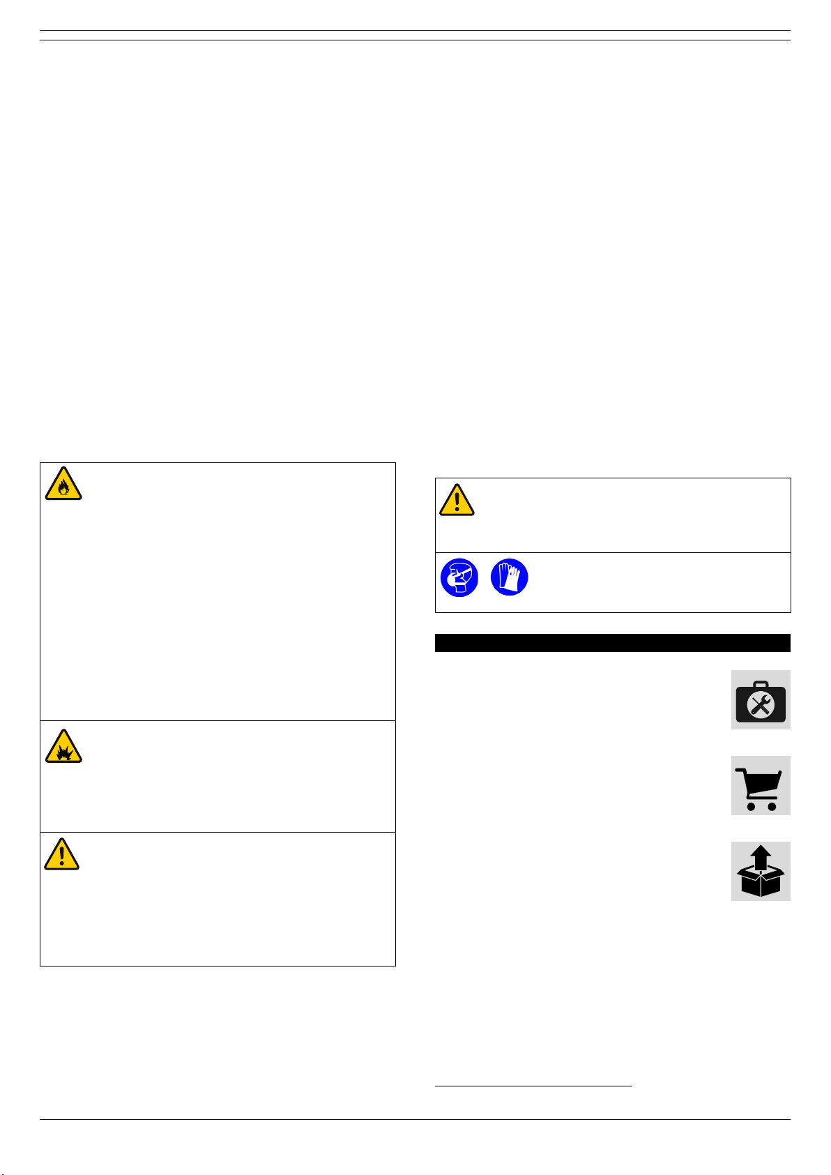
WARNING!
Fire hazard! Do not use the product in combination
- polishing applications in combination with
grinding, welding or any other application that
generate sparks
exposed to sparks)
- arc-air gouging
-
or solids or liquids
- extracting of aggressive fumes (such as
hydrochloric acid) or sharp particles
- extracting dust particles which are released when
welding surfaces treated with primer
- sucking cigarettes, cigars, oiled tissues, and other
burning particles, objects, and acids
WARNING!
Explosion hazard! Do not use the product for
explosion-hazardous applications, e.g.:
- aluminium laser cutting
- grinding aluminium and magnesium
- explosive environments or explosive substances/
gases
WARNING!
Do not use the product for:
- extraction of hot gases (more than 70°C/158°F
continuously)
-
- oil mist
- heavy oil mist in welding fume
- extraction of cement, saw dust, wood dust etc.
• Inspect the product and check it for damage. Verify the
functioning of the safety features.
• During use, always use Personal Protective Equipment
(PPE) to avoid injury. This also applies for persons who
enter the work area.
• Check the working environment. Do not allow unauthorised
persons to enter the working environment.
• Protect the product against water and humidity.
•
• Make sure that the workshop, in the vicinity of the product,
Service, maintenance and repairs
• Obey the maintenance intervals given in this manual.
Overdue maintenance can lead to high costs for repair and
revisions and can render the guarantee null and void.
• Always use Personal Protective Equipment (PPE) to avoid
injury. This also applies for persons who enter the work
area.
•
• Use tools, materials, lubricants and service techniques
which have been approved by the manufacturer. Never use
worn tools and do not leave any tools in or on the product.
• Safety features which have been removed for service,
maintenance or repairs, must be put back immediately
still function properly.
•
working on a higher level than 2 metres (local restrictions
may apply).
• Clean the area afterwards.
ATTENTION
Service, maintenance and repairs must be
performed in accordance with directive TRGS 560
persons (skilled) using appropriate work practices.
Personal protective equipment (PPE)
Wear respiratory protection and protective
gloves during service, maintenance and
repairs.
4 INSTALLATION
4.1 Tools and requirements
You need the following tools and requirements to
install the product:
- basic tools
4.2 To be sourced locally
You need the following material to install the
product:
- wall mounting hardware2
4.3 Unpacking
Make sure that the product is complete. The
package contains:
- extraction arm, incl. mounting bracket (fully
assembled)
If parts are missing or damaged, contact your supplier.
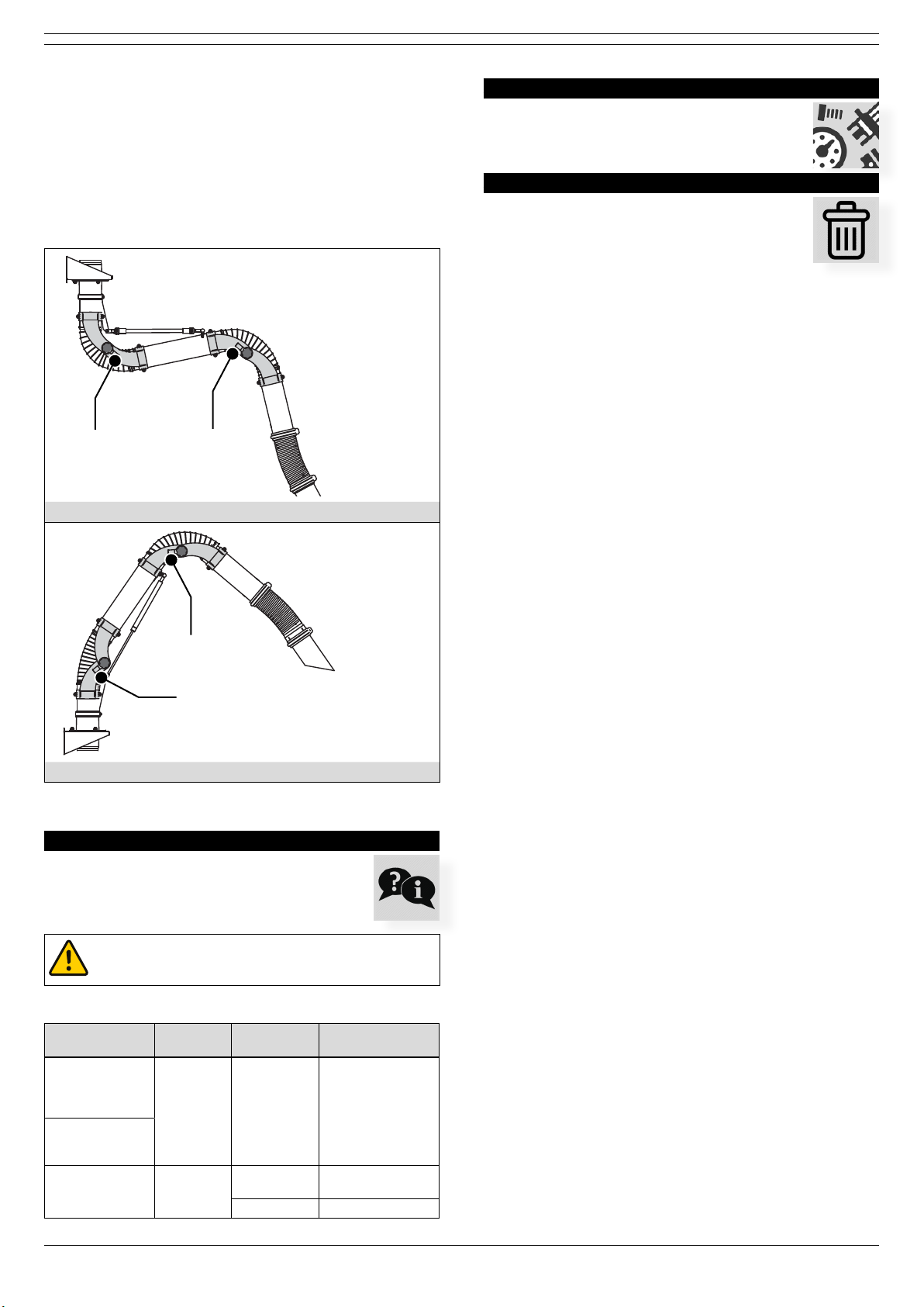
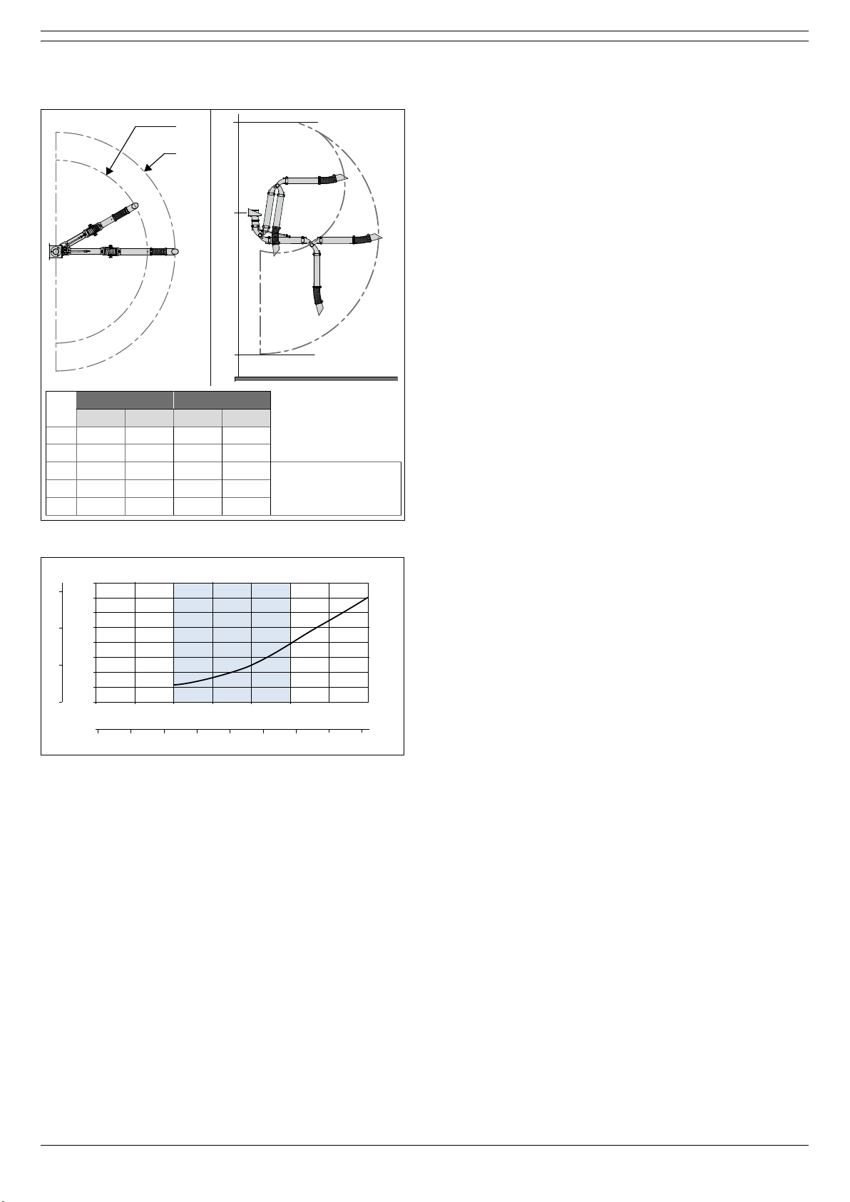
4.4 Installation height
You can install the MiniMan arm at any desired height. For
mounting examples, refer to page 8;
- Fig. III: “H” types
- Fig. IV: “S” types
2. The type of hardware depends on the wall type