NewLife SA3-S Guide
SA3-S
Protection against unintended car movement
INSTALLATION & COMMISSIONING MANUAL
a_SA3-S_2014-11_en 00-00000
SA3-S
A3
0035
X1 For further details please see instruction X2
left
digit Operating
state
Outside
Door open
Door zone
Approach
Relevelling
Exit
Display Description
Approach speed
Relevelling speed
Approach overshoot
UCM outside of door zone (A3)
UCM relevelling (A3)
Acceleration
Can not test solenoid
Override
Solenoid feedback
Door zone
Lost of traction
Position encoder
EMC interference
Door relay monitor
Safety circuit relay monitor
Internal
Aufkleber S/N
SW - / HW - Version
Herstelldatum
right
digit door
input SCCT-
input SCCT-
Relay Solenoid
0open off open off
1closed off open off
2open on open off
3closed on open off
4open off closed off
5closed off closed off
6open on closed off
7closed on closed off
8open off open on
9closed off open on
Aopen on open on
bclosed on open on
Copen off closed on
dclosed off closed on
Eopen on closed on
Fclosed on closed on
Magnet RESET
Normal operation (display lights continuously) Error (display flashes)

SA3-SInstallation&CommissioningManual
Manufacturer NEWLIFTSteuerungsbauGmbH
LochhamerSchlag8
82166Graefelfing
Tel +49 89 – 898 66 – 0
Fax +49 89 – 898 66 – 300
Mail [email protected]
www.newlift.de
Service line Tel +49 89 – 898 66 – 110
Mail [email protected]
First version 16.11.2012
Author BP
Last change 04.11.2016AL/EP
Release 06.12.2016AL
Hardware version V1.41/V1.50
Software version
Doc. No. mia_SA3S_2016-12_en
Copyright ©NEWLIFTSteuerungsbauGmbH,2016.
Thismanualisprotectedbycopyright.Allrights,includingthoseofcopying,of
reproduction,oftranslationandofmodification,inwholeorinpart,arereservedby
thepublisher.
Nopartofthisdescriptionmaybereproducedinanyformorcopiedwithan
electronicreplicationsystemwithoutwrittenpermission.
Althoughgreatcarehasbeentakenintheproductionoftextsandfigures,we
cannotbeheldlegallyliableforpossiblemistakesandtheirconsequences.

SA3-SInstallation&CommissioningManual 3
Content
1 About this manual 5
1.1 General 5
1.2 Abbreviations and symbols used 5
2 General safety regulations 6
2.1 Qualifications of the installing engineer 6
2.2 Residual dangers 6
2.3 Safety regulations 7
3 Technical data 9
4 Planning the system 10
5 Interfaces 12
5.1 Circuit variants 12
5.1.1 Ageneralvariant 13
5.1.2 Thesystemwithoutdoorbypass 14
5.1.3 Thesystemwithautomaticdoors 15
5.1.4 Thesystemwithmanualdoors 16
5.2 Connection to the control system 17
5.2.1 Standardcable(16-pin) 17
5.2.2 NEWLIFT cable(12-pin)withtheadditionalencodercable 18
5.3 Connection to the safety circuit 19
5.3.1 Ageneralvariant 20
5.3.2 Thesystemwithoutdoorbypass 21
5.3.3 Thesystemwithautomaticdoors 22
5.3.4 Thesystemwithmanualdoors 23
5.4 Display 24
5.4.1 Normaloperation 24
5.4.2 Errormessages 26
5.5 Remote Display Module 28
5.5.1 UserInterfaces 28
6 Installation 29
7 Commissioning 30
7.1 Remote Display Module 30
8 Behaviour in case of errors 31
9 Function test during commissioning 32
10 Inspection during commissioning 36
11 Annual inspection 39
12 Replacing existing systems 40
13 Waste disposal 41
14 Appendix 42

4 SA3-SInstallation&CommissioningManual
14.1 Release of trapped persons 42
14.2 Calculating the stopping distance 43
14.2.1 Downwardstoppingdistance 43
14.2.2 Upwardstoppingdistance 44
14.3 Capacitive coupling 45
14.3.1 Basics 45
14.3.2 Application 45
14.3.3 Avoidance 48
15 Certificate of EU-Tape Examination 49
16 Declaration of conformity 62
About this manual
SA3-SInstallation&CommissioningManual 5
1 About this manual
The SA3-S safety device was developed to satisfy the "protection against unintended car movement" stipulated
in the standard (EN 81-1:1998+A3:2009, 9.11).
Read these instructions carefully before installing and commissioning the safety device. In addition, chapter „2
General safety regulations“.
Objectives of this manual:
› Provision of the technical data
› Installation and commissioning instructions
› Maintenance instructions
› Test instructions
› Operation of the device.
1.1 General
This manual is intended to simplify installation and commissioning of the safety device. In addition, this manual
also serves as a reference for the operator.
It describes the commissioning, installation and maintenance procedures for a lift in connection with the SA3-S
safety device for the "protection against unintended car movement".
It contains important information for safe and proper installation and commissioning of the safety device.
Following these instructions will help to:
› prevent danger,
› avoid repair costs and downtime,
› increase the reliability and lifespan of the control system and of the lift system.
Local, national and on-site regulations regarding health and safety and protection of the environment must be
taken into account in addition to this installation and commissioning manual.
This manual only describes the assemblies of the lift system delivered by NEW LIFT. For information about
components of the lift system that were not manufactured and supplied by NEW LIFT, please refer to the res-
pective user information supplied by the manufacturer or supplier.
1.2 Abbreviations and symbols used
The following signs and symbols are used for operational instructions:
Abbreviation Description
SCCT Safetycircuit
PE ProtectiveEarth;earthwire
GND Ground;referencepotentialforsignalandoperatingvoltages
AC Alternatingcurrent
DC Directcurrent
GB Overspeedgovernor
Safety-relevant information
This symbol is located in front of safety-relevant information.
Information notice
This symbol is located in front of relevant information.
General safety regulations
6 SA3-SInstallation&CommissioningManual
2 General safety regulations
All important safety regulations are summarised in this chapter. These safety instructions must always be adhe-
red to during all work on the installation.
All persons performing installation and commissioning work on the SA3-S safety device must read this chapter
and follow its regulations.
Laws, regulations, guidelines and standards that apply in the country of operation must be followed in addition
to the safety regulations mentioned in this manual.
2.1 Qualifications of the installing engineer
The installing engineer must:
› be over 18 years of age (exception: apprentices who are over 16 years of age and are permanently supervised
by an engineer qualied for training apprentices).
› have rst aid training,
› have theoretical and practical knowledge of regulations and measures for the prevention of re and explosions
in his work area,
› be able to identify, avoid and rectify all dangers that might occur during his work in the shaft and in the operating
rooms,
› be able to identify and rectify all irregularities and faults that might occur during installation and operation of a lift
system,
› have theoretical and practical knowledge of operating principles and requirements of electric controls and drive
systems.
All installation and commissioning work on electric and electronic components of the safety device must be
performed by or supervised by a qualied electrician.
A qualied electrician has appropriate training and knowledge of regulations that allow him to judge the quality
of the work performed and identify possible dangers (BGV A3).
2.2 Residual dangers
Danger for persons
The following shall always apply during all work on the installation:
Danger to life! Do not touch live parts while working on electrical equipment.
› Before starting work, make sure the system is off circuit.
› Only carry out any installation work on electrical components when these are switched off and in an unpowered
state.
› Only use insulated tools when working on electrical system components.
› Pay attention to the accident prevention regulations.
Electrical hazard, leaking gas or water due to pierced supply lines. Risk of serious injury or death.
› Make sure no supply lines are in the installation location before starting any installation work.
›Danger of falling! Installing engineers and unauthorised persons can fall down the shaft. Risk of serious injury or
death.
› Block the shaft access points.
› Use suitable protection (e.g. safety harnesses, scaffoldings) when working on or in the shaft.
Danger of crushing due to intentional or accidental car movement. Risk of serious injury or death.
› Block the shaft access points.
› Before starting any work, make sure that there are no persons in the shaft or in the vicinity of moving parts of
the drive.
› Prevent unauthorised operation of the control system.

General safety regulations
SA3-SInstallation&CommissioningManual 7
Risk of material damage
The following shall always apply during all work on the installation:
Electrostatic charging
› Keep the electronic assembly in its original packaging until installation.
› Before opening the original packaging, a static discharge must be performed. To do this, touch a grounded
piece of metal.
› During work on electronic assemblies, periodically perform this discharge procedure.
Electronic assemblies are destroyed by defective, interchanged or incorrectly mounted connectors, short-circui-
ting or excess voltage.
› Check plugs for mechanical damage.
› Never change pre-assembled connectors or cables.
› Only connect loose or torn off wires according to circuit diagram details if this is possible on site (suitable mate-
rial and tools must be available).
› Pay attention to coding pins and latch lugs.
2.3 Safety regulations
General
› The instructions of the lift manufacturer and the instructions in this manual must be followed during installation
and commissioning of the safety device.
› The shaft must be secured against unauthorised trespassing during installation, commissioning, inspection and
maintenance.
› Assemblies, devices and cables must be installed and fastened securely and permanently.
› Loads must be moved with suitable aids (lift trucks, hoisting gear etc.).
› Sharp and pointed tools or other potentially dangerous objects may only be carried along in clothing if suitable
protective measures have been taken to rule out any danger.
› Alcohol and drugs must not be consumed before and during installation and commissioning.
Documentation
› A copy of the installation and commissioning manual must be available to the installing engineer at the time of
installing and commissioning.
› A copy of the installation and commissioning manual and the wiring diagrams must be kept in the control cabi-
net at all times after installation.
› The wiring diagrams supplied with the SA3-S safety device are binding. Changes must only be made after con-
sulting NEW LIFT and must be documented in writing on the system.
› The factory-side inspection records of the SA3-S safety device remain with the manufacturer.
Electricity
› Regulations for installing and operating electrical equipment (VDE 0100) and regulations of local utilities must
be followed.
› The specied distances between different electrical assemblies must be controlled and maintained.
› All installation work must be carried out with the system shut down and off circuit.
› All cables and wires must be installed with sufcient strain relief.
› The neutral and ground wires must be routed separately.

General safety regulations
8 SA3-SInstallation&CommissioningManual
Working in the shaft
› Any work in the shaft requires perfect and permanent communication between the supervisor on the lift control-
ler and the workers in the shaft.
› Components in the shaft must be arranged or secured in such a way that persons accessing the shaft for ins-
pection, maintenance or repair purposes are not in danger.
› The maximum load of the lift system must not be exceeded.
› The specied overruns of the emergency end switches in relation to the speed must be observed.
› The emergency installations must not be activated during normal operation.
› All emergency installations and braking systems must be checked for trouble-free operation and all shaft entran-
ces closed off before beginning work.
› Installation and operation are prohibited if other persons could be in danger.
› Workers must be secured against falling.
› In case of any work interruptions, the car must be moved to the lowest stop position, the control system swit-
ched off and the power supply (e.g. UPS) permanently disconnected.
Personal safety equipment of the installing engineer
› Eye protection
› Safety boots
› Protective helmet
› Safety harness
› Clothing suitable to the ambient conditions of the installation location
› Jewellery, watches and similar items may not be worn; a hair net must be used if applicable.
Handling electronic assemblies
› Leave electronic assemblies in their original packaging until installation.
› Touch a grounded piece of metal prior to opening the original packaging to prevent damage from static charges.
Waste disposal
› All packaging material must be disposed of in an environmentally acceptable manner; paper, plastic, metal,
electronic assemblies etc. must be recycled.
Technical data
SA3-SInstallation&CommissioningManual 9
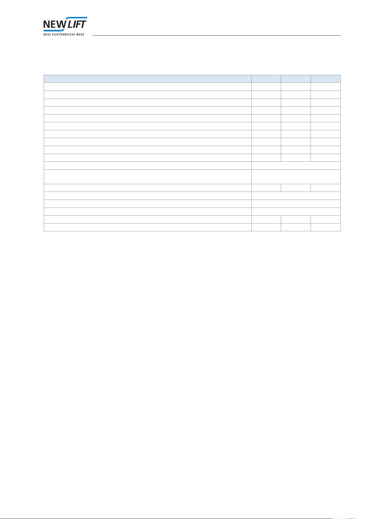
3 Technical data
Parameters Min. Type Max.
Operating voltage1 24V DC
Power consumption with energised solenoid 1A
Power consumption with deenergised solenoid 0.3A
Temperature: operation 0°C 65°C
Temperature: storage & transport -20°C 70°C
Relative humidity: operation (non-condensing) 15% 85%
Relative humidity: storage & transport (non-condensing) 5% 95%
Cable length to overspeed governor2 100m
Cable length to control system 100m
Error-signal output current 0.7A
Protection type IP64
Possible safety circuit voltages3 230V/50Hz, 110V/50Hz,
24VDC - 150VDC
Safeguarding of the safety circuit (external) 4A
Position resolution (pulse interval) with HJ200 0.94mm
Position resolution (pulse interval) with HJ250 0.94mm
Position resolution (pulse interval) with HJ300 0.92mm
Reaction time "A3" until solenoid has deenergised 82 ms
Service life 20 years
Table 1: Technical data
1 The operating voltage must also remain active during a power failure of the main supply (see chapter "Planning the
system").
2 The maximum possible cable length to the overspeed governor and to the control system is heavily dependent on the
distance of the cable to other sources of interference.
3 Possible safety circuit voltages: The required voltage must be specied when ordering

Planning the system
10 SA3-SInstallation&CommissioningManual
4 Planning the system
In order to use the SA3-S safety system together with a lift system, the following requirements must be satised:
1. The lift control system must make available a signal that always becomes inactive when the car
is not to be moved ("in motion" signal). This signal must be inactive on each stop. Level: 0V (car is
moving) / 24V or high impedance (car is not moving). The signal is needed in order to test the solenoids
at the overspeed governor and to allow that the magnetic coil drops with closed doors (quiescent state
of the lift).
2. The product must be supplied with power via a 24V emergency power device.
Reason: If power fails during travel, the solenoids must remain energised until the car stops, as the
safety gear will otherwise be actuated. This delay is taken into account in the device, but can only take
effect if the power supply is ensured for several seconds following power failure. Required is 24V/1A
for about 10 sec. In addition, an UPS is needed in order to energise the solenoid during an emergency
rescue so that the car can be moved. The emergency power supply must be designed accordingly.
3. An override input ensures that the car can also be moved in the event of a power failure so that per-
sons can be freed.
In the override state, the solenoid energises and the safety circuit relay opens. Level: 0V (override) /
high impedance (normal operation). For override, a separate switch must be wired in the control cabi-
net. It is to be labelled with "Ovrd. SA3-S".
4. The safety gear that is to be used in combination with the SA3-S must satisfy the requirements of EN
81-1:1998 + A3:2009 or EN81-2:1998 + A3:2009
5. The car apron must satisfy the requirements of EN 81-1:1998 + A3:2009 point 8.4.
An apron acc. to EN 81-21 is permissible only if the car apron satises the requirements specied in
EN 81-1, section 8.4 over the entire shaft upon leaving the lowest oor. If this cannot be ensured, the
calculation of the permissible upward stopping distance (see chapter "Upward stopping distance") can
only take into account the vertical part of the car below the car threshold for the apron length.
6. A formula must be used to theoretically verify that the car achieves the stopping distance specied in
the standard. The "upward" and "downward" cases are to be calculated separately. The following data
are necessary for this purpose:
› Maximum length of the door zones in the up and down directions (normally 200mm in both
directions)
› Maximum reaction path of safety gear and overspeed governor (the path of the car from the
time the safety cable is blocked until the safety gear reaches its guaranteed braking decelera-
tion) in both directions
› Minimum braking deceleration of the safety gear in both directions
› Internal passage height to the car interior (for calculating the maximum downward stopping
distance)
› Length of the apron below the car (for calculating the maximum upward stopping distance)
› Mass of empty car, cable and counterweight (for calculating the maximum possible upward
acceleration)
The product may only be used if the required stopping distances can be achieved. For some parame-
ters, standard values may be used.
7. The safety circuit of the lift system must be modied according to the specications. In the standard
device, the safety circuit voltage is 230V / 50Hz. Other voltages are possible on request.
8. The PowerGood input signals a power failure at the control system. Level: 24V: current present / 0V or
high impedance: power failure. Ideally, this input is supplied by the power supply of the control system.
9. If the system is equipped with the "approach with open doors" function, the two door zone signals
must be wired. These signals must also be monitored by an external safety circuit bypass control. Level:
24V (door zone) / 0V or high impedance (outside of the door zone).
10. To reset the product in the A3 case or after an error, a button ("reset") can be wired in the control
cabinet. Level: 24V (reset) / 0V or high impedance (normal operation). The button is to be labelled with
"Reset SA3-S". Alternatively, the SA3-S safety device can be reset with the aid of a magnet below the
display.
11. The "error" output of the product can be wired with an error lamp (24V, max. 0.7mA) or with the control
system. This output is for information only and is not a safety function. The error lamp is not necessary if
the device display can be viewed.If the error output is read by the controller, the controller must not stop
the system in case of an error.

Planning the system
SA3-SInstallation&CommissioningManual 11
12. Reset button and error display can be replaced by a "display module" in the control cabinet.
13. Position: SA3-S generates a two-channel incremental output which can be used as a position input for
the control system. The resolution of the output is better than 1mm. Level: differential driver stage (2x
two-wire)
14. For the purpose of the arrest test, a button (N.C.) can be connected in the power supply of the device
(connection B-3). Upon actuation of the button, the solenoid on the overspeed governor deenergises
and the safety gear is triggered.
15. The SA3-S safety system can be installed in hydraulic lifts. If a double-acting safety gear is used here,
the same premises apply as to rope lifts. If only one safety gear should be used in the downwards direc-
tion, the following requirements must be met:
› Safety gear in the downwards direction must conform to the requirements of EN81-2:1998 +
A3:2009.
› According to EN 81 the speed restrictor must also have force guided safety switches which
opens the safety circuit in upward direction during magnet releasing.
› Voltage of safety circuit must act directly on the braking element (e. g. motor contactor), i. e. by
opening the safety circuit the car must come to a standstill through gravitational force.
16. In case of hydraulic lifts the safety gear should not get jammed, during the car with the releasing sole-
noid coil is sinking slowly. For that prupose, the controller might activate the signal „in motion“for a short
time.
17. The SA3-S safety device has electronic inputs. In order to avoid disturbances of the system, carry out
suitable interference suppression measures. These include:
› Suppression circuits of all inductors (contactor, relay, brake systems…)
› Suitable line lter for disruption of safety circuit from motor control
› Suitable shielding of the cables to the motor and to the the inverter etc.
› As possible a separate laying of the disturbing cable lines
18. Your order should indicate the connection variant (NEW LIFT cable or standard cable)

Interfaces
12 SA3-SInstallation&CommissioningManual
5 Interfaces
5.1 Circuit variants
There are 4 valid circuit variants for the SA3-S safety system. The following information applies to all variants:
› In case there is no door bypass in the system, the two door zone inputs are not required, they are left open. The
rest of the circuit will remain consistently. It is advisable to use in this case variant 2.
› Both GND potentials (from the power supply 24V and 24V emergency power supply) can be connected together
externally.
› If the system has the auxiliary control, the safety circuit relay can be placed in the safety circuit, where it is
bypassed by the auxiliary control. Safety circuit relay can be located at any position in the safety circuit, e.g.
also in front of the door contacts.
Attention! During simultaneous use of override and auxiliary control make sure that all shaft and car doors are
closed.

Interfaces
SA3-SInstallation&CommissioningManual 13
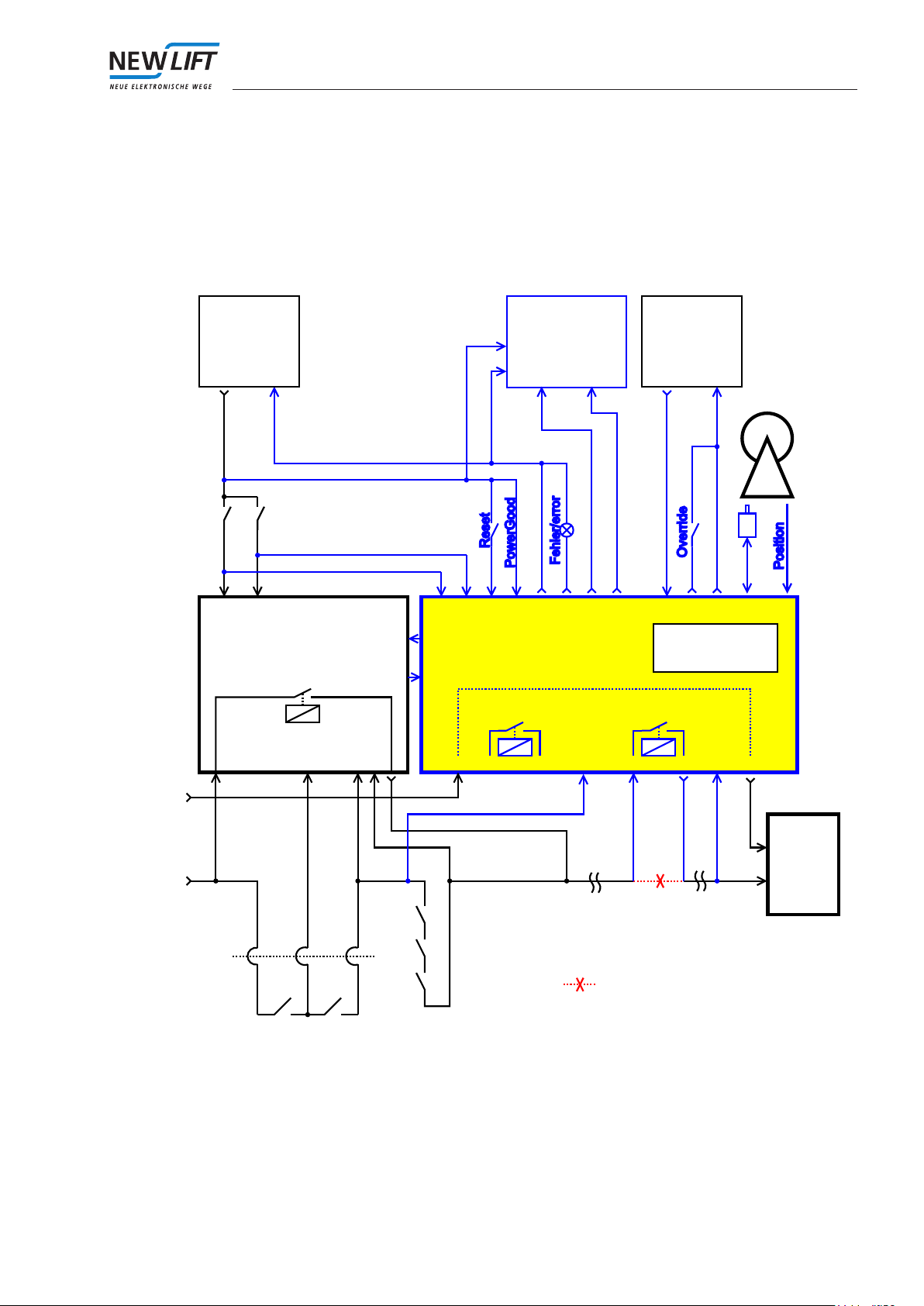
5.1.1 A general variant
The general variant can be used for all types of installations. However, it is recommended to examine the imple-
mentation in order to minimise the wiring effort. The variants from 2 to 4 shall be reviewed for implementation.
Hängekabel/
trailing cable
Fahrkorbtüren/
cabin door
B A
Türumgehung/door overbridge
(Sicherheitsschaltung/
safety circuit)
Sicherheitskreis/
safety circuit Sicherheitskreis/
safety circuit
Aufzug-
steuerung/
lift control
Sperrmittel/
shaft doors
SA3-S
Geschwindig-
keitsbegrenzer/
overspeed
governor
Türzone/
door zone
Position
InFahrt/
moving
Motor-
schütze/
motor
contactor
Tür-Relais/
door relais
SHK-Relais/
safety circuit relais
C-1 C-3 D-1 D-3C-6 D-5
C-2 D-2
N-Leiter/neutral
A-3 A-8 A-7 A-1 A-2
Netzteil/
power supply
GND24VDC
Notstrom-
versorgung/
backup supply
GND24VDC
A-6
B-1,B-2
B-5,B-6
A-4
A-5 B-3 B-7
Externes Display/
external display
B-4 B-8
N
S/N: 250 8/11
HW: VX.XX (230V/50Hz)
SW: XXXXXXXX
TÜV-A-AT-1/11/256CEES/X
Türzone A/door zone A
Türzone B/door zone B
Variante 1:
Auftrennung des Sicherheitskreises
disruption of safety circuit
Figure 1: Overview of the complete system (variant 1)

Interfaces
14 SA3-SInstallation&CommissioningManual
5.1.2 The system without door bypass
If the system does not have a door bypass, the door input is connected behind the last door in the safety circuit.
The door relay has no function in this case.
Hängekabel/
trailing cable
Fahrkorbtüren/
cabin door
B A
keine Türumgehung/
no door overbridge
Sicherheitskreis/
safety circuit Sicherheitskreis/
safety circuit
Aufzug-
steuerung/
lift control
Sperrmittel/
shaft doors
SA3-S
Geschwindig-
keitsbegrenzer/
overspeed
governor
Position
InFahrt/
moving
Motor-
schütze/
motor
contactor
Tür-Relais/
door relais
SHK-Relais/
safety circuit relais
C-1 C-3 D-1 D-3C-6 D-5
C-2 D-2
N-Leiter/neutral
A-3 A-8 A-7 A-1 A-2
Netzteil/
power supply
GND24VDC
Notstrom-
versorgung/
backup supply
GND24VDC
A-6
B-1,B-2
B-5,B-6
A-4
A-5 B-3 B-7
Externes Display/
external display
B-4 B-8
N
S/N: 250 8/11
HW: VX.XX (230V/50Hz)
SW: XXXXXXXX
TÜV-A-AT-1/11/256CEES/X
Variante 2:
24VDC GND
Auftrennung des Sicherheitskreises
disruption of safety circuit
Figure 2: Overview of the complete system (variant 2)
Interfaces
SA3-SInstallation&CommissioningManual 15
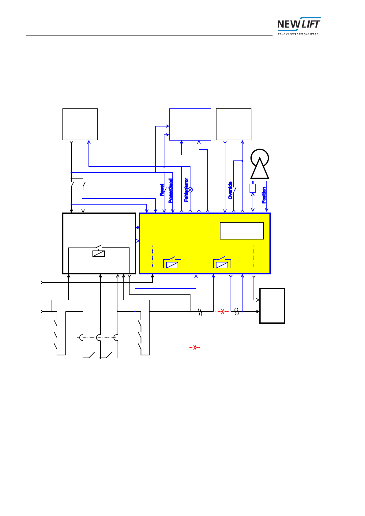
5.1.3 The system with automatic doors
If the system has automatic doors, i.e. during normal operation shaft and car doors always open simultaneously,
the door input is connected between car and shaft doors (door lock) in the safety circuit. The door relay has no
function in this case.
Hängekabel/
trailing cable
Fahrkorbtüren/
cabin door
B A
Türumgehung/door overbridge
(Sicherheitsschaltung/
safety circuit)
Sicherheitskreis/
safety circuit Sicherheitskreis/
safety circuit
Aufzug-
steuerung/
lift control
Sperrmittel/
shaft doors
SA3-S
Geschwindig-
keitsbegrenzer/
overspeed
governor
Türzone/
door zone
Position
InFahrt/
moving
Motor-
schütze/
motor
contactor
Tür-Relais/
door relais
SHK-Relais/
safety circuit relais
C-1 C-3 D-1 D-3C-6 D-5
C-2 D-2
N-Leiter/neutral
A-3 A-8 A-7 A-1 A-2
Netzteil/
power supply
GND24VDC
Notstrom-
versorgung/
backup supply
GND24VDC
A-6
B-1,B-2
B-5,B-6
A-4
A-5 B-3 B-7
Externes Display/
external display
B-4 B-8
N
S/N: 250 8/11
HW: VX.XX (230V/50Hz)
SW: XXXXXXXX
TÜV-A-AT-1/11/256CEES/X
Türzone A/door zone A
Türzone B/door zone B
Variante 3:
Automatische Türen/automatic doors
Auftrennung des Sicherheitskreises
disruption of safety circuit
Figure 3: Overview of the complete system (variant 3)
Interfaces
16 SA3-SInstallation&CommissioningManual
5.1.4 The system with manual doors
If the system has the manual doors, that have a manual door contact as well as a bolt contact (door lock) in the
safety circuit, the door input is connected between manual door contact and bolt contact. The order of the car
door switch in the safety circuit is not important in this case.
Hängekabel/
trailing cable
Fahrkorbtüren/
cabin door
B A
Türumgehung/door overbridge
(Sicherheitsschaltung/
safety circuit)
Sicherheitskreis/
safety circuit
Aufzug-
steuerung/
lift control
Sperrmittel/
shaft doors
SA3-S
Geschwindig-
keitsbegrenzer/
overspeed
governor
Türzone/
door zone
Position
InFahrt/
moving
Motor-
schütze/
motor
contactor
Tür-Relais/
door relais
SHK-Relais/
safety circuit relais
C-1 C-3 D-1 D-3C-6 D-5
C-2 D-2
N-Leiter/neutral
A-3 A-8 A-7 A-1 A-2
Netzteil/
power supply
GND24VDC
Notstrom-
versorgung/
backup supply
GND24VDC
A-6
B-1,B-2
B-5,B-6
A-4
A-5 B-3 B-7
Externes Display/
external display
B-4 B-8
N
S/N: 250 8/11
HW: VX.XX (230V/50Hz)
SW: XXXXXXXX
TÜV-A-AT-1/11/256CEES/X
Türzone A/door zone A
Türzone B/door zone B
Variante 4:
Drehtüren/manual doors
Auftrennung des Sicherheitskreises
disruption of safety circuit
Drehtürkontakte/
manual door contacts
Figure 4: Overview of the complete system (variant 4)

Interfaces
SA3-SInstallation&CommissioningManual 17
5.2 Connection to the control system
There are two different variants for the connection to the control system: the 16-pin standard cable and the
12-pin NEW LIFT cable with the additional encoder cable.
5.2.1 Standard cable (16-pin)
The specied wire colours apply for the 16-pin standard cable:
SA3-S Wire Signal Level4
A-1 white PowerGood (input, high-active), the signal must become inacti-
ve in the event of a power failure (emergency power operation)
24V: no power failure
A-2 brown Error (output, high-active), the output can control a small error
lamp or similar
24V: error
A-3 green Door zone A (input, high-active) 24V: door zone
A-4 yellow Override (input, low-active) 0V: override
A-5 grey GND (control system, not buffered)
A-6 pink InMotion (input, low-active) 0V: InMotion
A-7 blue Reset (input, high-active), input for resetting an error state 24V: reset
A-8 red Door zone B (input, high-active) 24V: door zone
B-1 black Position /A (output) line driver
B-2 violet Position /B (output) line driver
B-3 grey/pink 24V emergency power supply
B-4 red/blue Display module (output, D-) line driver
B-5 white/green Position A (output) line driver
B-6 brown/green Position B (output) line driver
B-7 white/yellow GND emergency power supply
B-8 yellow/brown Display module (output, D+) line driver
Table 2: Pin assignments for the control system standard cable
4 The unspecied input levels can be set to the opposite potential or be high impedance.
PowerGood (A-1):
The signal indicates to the safety device whether the power supply of the lift is OK. During emergency power
operation, the safety device is separated from the power supply 10 sec. after the car is stopped to avoid loading
the supply batteries unnecessarily.
Error (A-2):
The output indicates that an error which must be reset manually has occurred in the device. A small signal lamp
can be operated on this output. Alternatively, the error can be read on the display.
Door zone (A-3, A-8):
The two door zone inputs indicate that the car is currently in a door zone. They must be independent of one
another (2-channel).
The door zone inputs must be monitored by a tested safety circuit bypass control (EN81-1, 14.2.1.2) which
prevents operation of the lift in case of an error (EN81-1, 14.1.2.3.2.1.).
The door zone inputs are not connected, if the installation has no door bypass (the safety circuit bypass control).
Override (A-4):
If the override input is set to GND, the solenoid energises. It is used for freeing persons. If the safety device is
supplied with power (PowerGood), an error is detected, that ensures that the safety circuit is opened. The over-
ride input also functions in the event of a power failure, since this function is supplied by the emergency power
battery. If override is not active, the input must be high impedance.
Interfaces
18 SA3-SInstallation&CommissioningManual
Attention: The car must not be moved if the solenoid is deenergised, since the safety brake is then active. The
emergency release should remain locked until the override is active.
InMotion (A-6):
The input is used to signal to the safety device that the car is to be moved by the control system. It is needed
for testing the solenoid. In addition, the solenoid deenergises if the car is at a standstill with closed doors (not
"InMotion").
This measure serves to save wear and tear on the solenoid and helps to reduce the stand-by losses. The refe-
rence potential is GND (A-5)
Reset (A-7):
An error state can be reset via this input (see chapter "Behaviour in case of errors").
Position output (B-1, B-2, B-5, B-6)
The control system can be supplied with an incremental position signal via the position output. The reference
potential is GND (A-5)
Display module (B-4, B-8):
An external display module can be connected via this output. It has the same display as the internal display. The
internal 7-segment display on the remote display module is duplicated.
5.2.2 NEW LIFT cable (12-pin) with the additional encoder cable
The specied wire colours apply for the 12-pin NEW LIFT cable:
SA3-S Wire Signal Level5
A-1 white PowerGood (output, high-active), the signal must
become inactive in the event of a power failure
(emergency power operation)
24VDC: no power failure
A-2 brown Error (output, high-active), the output can control a
small error lamp or similar
24VDC: error
A-3 green Door zone A (input, high-aktiv) 24VDC: door zone
A-4 yellow Override (input, low-aktive) 0V: override
open: override off
A-5 grey GND (control system, not buffered)
A-6 pink InMotion (input, low-active) 0V: InMotion
A-7 blue Reset (input, high-active), input for resetting an
error state
24VDC: reset
A-8 red Door zone B (input, high-aktiv) 24VDC: door zone
B-3 black 24V emergency power supply
B-4 violet Display module (output, D-) line driver
B-7 grey-pink GND emergency power supply
B-8 red-blue Display module (output, D+) line driver
Table 3: Pin assignments for the control system NEW LIFT cable
5 The unspecied input levels can be set to the opposite potential or be high impedance.
Encoder cable:
This cable includes the encoder signals with a NEW LIFT compatible plug for FST-2.
Nr. Wire colour SafeBox Signal Internal
1 B-1 position /A (output, line driver) position_/A
2 B-2 position /B (output, line driver) position_/B
3 B-5 position A (output, line driver) position_A
4 B-6 position B (output, line driver) position_B
Table 4: Pin assignments NEW LIFT encoder cable
The descriptions of the signals correspond to the descriptions in chapter 5.2.1.

Interfaces
SA3-SInstallation&CommissioningManual 19
5.3 Connection to the safety circuit
As already explained above (see chapter „circuit types “), there are four possibilities to integrate the system in
the safety circuit of installation.
The system can be delivered for various voltage types of safety circuit (AC and DC). The standard version is
230V/50Hz.
Terminal assignment of signals from the safety circuit:
SA3-S Wire Signal
C-1 1 Door simulation (input, door relay)
C-2 2 Input N-wire (AC) or GND (DC)
C-3 3 Door simulation (output, door relay)
C-4 4 Earth
C-5 5 Earth
C-6 6 Door safety circuit (door input)
D-1 7 Safety circuit relay (input, scct relay)
D-2 8 Output N-wire (AC) or GND (DC)
D-3 9 Safety circuit relay (output, scct relay)
D-4 10 Earth
D-5 11 Safety circuit (scct input)
D-6 PE Earth
Table 5: Pin assignments for the safety circuit
In general:
› The safety circuit must be opened at the input C-6, if the car door or a shaft door is opened.
› The N-wire (the GND wire) of safety circuit must be led over the safety device.
The separation of N-wire connection must cause deactivating of the main contactor!
› The auxiliary control can bypass the safety circuit with a force-guided contact. Bypassing is required to free
trapped passengers.
Interfaces
20 SA3-SInstallation&CommissioningManual
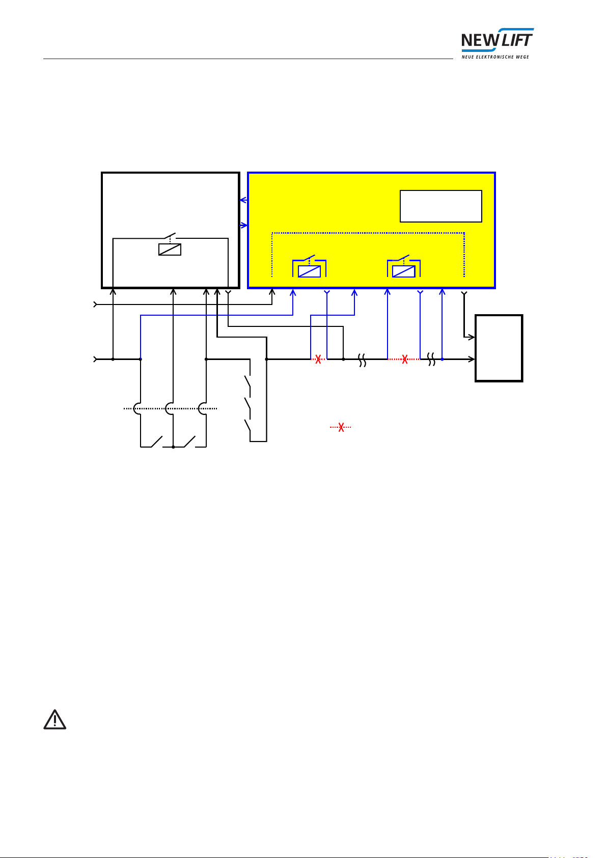
5.3.1 A general variant
The general variant can be used for all types of installations.
Hängekabel/
trailing cable
Fahrkorbtüren/
cabin door
B A
Türumgehung/door overbridge
(Sicherheitsschaltung/
safety circuit)
Sicherheitskreis/
safety circuit Sicherheitskreis/
safety circuit
Aufzug-
steuerung/
lift control
Sperrmittel/
shaft doors
SA3-S
Position
InFahrt/
moving
Motor-
schütze/
motor
contactor
Tür-Relais/
door relais
SHK-Relais/
safety circuit relais
C-1 C-3 D-1 D-3C-6 D-5
C-2 D-2
N-Leiter/neutral
A-3 A-8 A-7 A-1 A-2
A-6
B-1,B-2
B-5,B-6
A-4A-5 B-3 B-7B-4 B-8
N
S/N: 250 8/11
HW: VX.XX (230V/50Hz)
SW: XXXXXXXX
TÜV-A-AT-1/11/256CEES/X
Variante 1:
Auftrennung des Sicherheitskreises
disruption of safety circuit
Figure 5: Modication of the safety circuit (variant 1)
Explanation of the wiring diagram:
› The safety circuit is interrupted at the end of the series connection of the door contacts. The door contacts are
connected to input C-6.
› With the aid of the door relay, the safety device ensures that the safety circuit is closed if all doors are closed.
For this purpose, the start of the door series connection must be connected to input C-1, and the end (after
interruption) must be connected to C-3.
› The safety circuit input D-5 should be connected to the end of the safety circuit. It is responsible, among other
things for the detection of the loss of traction, i.e., if the a safety circuit is open but the car is still moving or is not
braked, it is „force-braked“.
› The relay of safety circuit can be looped in at any point in the safety circuit. It opens in case of an error (e.g.,
A3 detection) and is closed again by resetting the error. The safety circuit relay is not bypassed by override.
To release persons by means of auxiliary mode control, it must be placed at a point in the safety circuit that is
bypassed by auxiliary mode. The safety circuit relay is opened every 24 hours for a short time. This is neces-
sary to guarantee the proper operation of the relay.
Attention! During simultaneous use of override and the auxiliary control make sure that all shaft and car doors
are closed.
Table of contents
Popular Safety Equipment manuals by other brands

Lanex
Lanex PB-20 instruction manual

SKYLOTEC
SKYLOTEC ANCHOR ROPES Instructions for use

Besto
Besto Buoyancy Aid 50N Instructions for use

TEUFELBERGER
TEUFELBERGER NODUS Manufacturer's information and instructions for use

Troy Lee Designs
Troy Lee Designs Tbone Product owners manual

Innova
Innova Xtirpa Instruction and safety manual

bolle SAFETY
bolle SAFETY B810 quick start guide

SHENZHEN FANHAI SANJIANG ELECTRONICS
SHENZHEN FANHAI SANJIANG ELECTRONICS A9060T instruction manual

Hiltron security
Hiltron security POWER8E Installation and use manual

Salewa
Salewa MTN SPIKE user manual

Hatco
Hatco B-950P installation guide

Sitec
Sitec TX MATIC operating manual


