NewMar FDP 1010 Instructions for use

www.newmartelecom.com
P.O. Box 1306, Newport Beach, California 92663 ~ Phone: 714-751-0488 ~ Fax: 714-957-1621 ~ [email protected]
030-101796 REV C
0521-03C
June 2013
FUSE PANEL
Technical Practice
FDP 1010
10/10 GMT
NEBS Level 3 Certified
FEATURES
¾2 isolated groups (busses) of 10 GMT fuses in each (15Amps/GMT position)
¾Polarity insensitive (+/-24 or +/- 48 Vdc) battery voltage
¾This panel can operate at 200 Amps of output current per panel (100 Amps per Bus)
¾Barrier terminal strips for fused outputs and isolated returns (grounds)
¾Three sets of Form C relay contacts are provided to extend alarms
¾One set of alarm contacts for each; MAJOR Bus A, MAJOR Bus B and MINOR External Input Alarm
¾MINOR External Input Alarm provided on the ground signal applied to the input pin
¾Cable management bar (aka. towel bar) on rear panel included
¾Five spare fuse holders provided on the panel’s faceplate
¾Single 1.75” mounting height (single panel space)
¾Two sets of mounting brackets are supplied (1” & 1-3/4” spacing), both sets of brackets are universal for
19” and 23” racks, with flush and offset mounting options
¾NEBS level 3 certified, with zone 4 earthquake

1. GENERAL DESCRIPTION
1.1. The Newmar model FDP 1010 Fuse Panel
provides up to 20 circuits for the distribution of
DC power to equipment. Each of the 20 circuits
is individually protected by a GMT style
telecommunication fuse located on the panel's
faceplate. Alarm circuits are provided to indicate
and extend alarm conditions when faults occur.
Normal Operation LEDs are provided to indicate
the status of each bus in the panel.
1.2. Input wiring is connected to a high current,
2-hole lug input block located at the rear of the
panel. Each group of fuses or bus has its own
completely isolated inputs, allowing the
distribution of two battery voltages through the
same panel.
1.3. The power is distributed to the load side
equipment through GMT style fuses. There are
10 fuses per fuse group and two groups per
panel. Each fuse position is available for
installer connection at the rear of the panel. A
designation card is provided for keeping records
of which position is connected to which
equipment and what amperage is to be used.
1.4. Each panel is equipped with dummy fuses
in all unused positions. The panel also can hold
up to 5 spare fuses in the faceplate.
1.5. Alarm circuits are provided to alert service
personnel of fault conditions. A fuse alarm is
caused when any of the GMT distribution fuses
opens. A red Fuse Alarm LED on the faceplate
will illuminate and the green Normal Operation
LED will extinguish to signal a fuse alarm and
also the appropriate MAJOR relay contacts will
change states. These fuse panels have
common (C), normally open (NO) and normally
closed (NC) terminals for both Major and Minor
alarms. A Major alarm being a fuse or power
failure in that bus and a Minor alarm being an
external alarm. The external alarm is ground
activated (20mA required to activate alarm.)
Note, the use of the alarm contacts is optional, if
you do not wish to extend the alarms, you don’t
have to do anything with the alarm pins.
The “Normal” condition of the relay exists when
the panel is powered up without any blown
fuses or externally activated alarms.
The red External Alarm LED on the units face
plate will light when a ground is connected to
the MINOR “Alarm In” terminal (20mA max.
signal required to activate alarm.)
1.6. The N250120-N-L0521 Fuse Panels are
made from 0.050" steel and painted black.
Single rack height panels are shipped with two
sets of universal brackets (1” & 1-3/4” spacing)
that will fit both 19" and 23" wide racks and use
only one 1.75" panel space. The panel has a
clear L shaped lexan to protect the wiring
connections on the back of the panel.
2. APPLICATION
2.1. The N250120-N-L0521 Fuse Panels are
designed to be used in the distribution of DC
power. They are rack mount panels that can
provide fused DC power to up to 20 individual
circuits, or 10 pieces of equipment, providing
redundant battery feeds to each.
3. CIRCUIT DESCRIPTION
3.1. Power is connected to the fuse panel via
¼” studs on 5/8” centers located at the rear of
the panel (torque 5.5 ft-lbs.) These inputs are
high current stud blocks that supply current to
the fuse panel. Connect the battery return cable
to the stud input that is labeled “RTN” and the
Battery supply cable is connected to the
terminals labeled “BAT”.
3.2. Distribution of current from each bus is
provided by GMT style fuses. Each bus has 10
fuse holders for distribution; the fuses are
labeled F1 to F10 on each bus. Each fuse
position is made available at the rear of the fuse
panel. Maximum output current of each fused
position is rated at 15 Amps, provided the
maximum bus current or BDFB fuse is not
exceeded (each bus is rated at 100Amps max.)
3.3. Fuse alarm circuitry provides 1 set of form
“C” contacts (C, NO and NC) for each type of
alarm (Major Bus A, Major Bus B and Minor-
Ext). In the event of a fuse or external alarm,
the proper relay will change states, providing a
connection between the Normally Open “NO”
and Common “C” terminals. The normally
closed “NC” terminal will open to high
impedance. The MINOR indicates an external
ground input alarm (aka; bay or rack alarms.)
Ground activates the external alarm input.

4. INSTALLATION
Please read completely before beginning.
WARNING: Installation should only be performed
by an experienced Installer familiar with DC power
distribution systems.
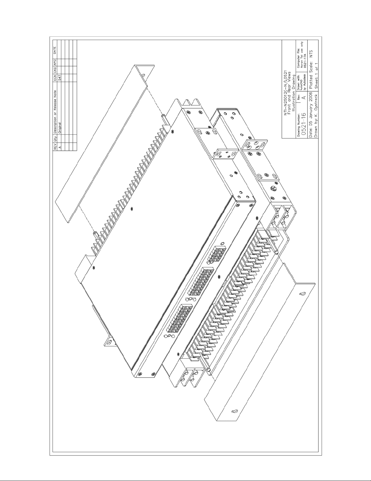
4.1. Unpack and inspect the Newmar Fuse Panel
for possible damage incurred during shipping. If
damage is found, file a claim immediately with the
carrier, and notify Newmar.
4.2. Once the panel is unpacked, verify that there
are two sets of mounting brackets (1” & 1-3/4”
spacing). Adjust the position and orientation of
the correct mounting brackets on the fuse panel,
such that it will fit the rack you wish to mount the
panel in. Single rack height panels have a
universal bracket that allows the panel to be
mounted on either 19" or 23" wide equipment
racks and can be installed for flush mounting of
the fuse panel, or for a 5" offset mounting.
4.3. Mount the panel on the equipment rack using
the thread forming #12-24 rack mounting screws
and tooth lock washers provided.
WARNING: For safety reasons all wiring should
be done with the power source removed (when
possible).
4.4. Remove the distribution fuse feeding the
input cables that are to be connected to the new
panel. Using input cables specified by the Job
Engineer, hook up the input cables to the input
terminal block on the fuse panel (“BAT” & “RTN”
for each bus). Each high current input terminal
uses a two hole compression lug (1/4” on 5/8”,
torque to 5.5 ft-lbs).
4.5. The battery outputs (“BAT”) are available at
the terminal blocks (#6 screw, up to 10awg fork)
at the rear of the panel. Each fuse position is
numbered and that circuit is available at the
terminal block position with the same number.
4.6. All battery return (“RTN”) connections are
also terminated on barrier strips (#6 screw, up to
10awg fork). Note, these returns are isolated
from the chassis frame.
4.7. This panel has MAJOR Bus A, MAJOR Bus
B and MINOR External alarms. Each alarm has a
common (C), normally open (NO) and normally
closed (NC) alarm contact.
The Minor External Input Alarm is used for alarms
that originate outside the panel (bay alarms). A
ground signal is supplied from another device in
the bay to activate this alarm.
In an alarm the “C” contact will short to the “NO”
contact, and the “NC” will open. Connect the
alarm connections as per your alarm system
requirements. Newmar recommends you fuse the
alarm battery supply (ABS) to 1A or less to protect
the alarm wiring and circuitry.
4.8. CHASSIS GROUND; For safety reasons,
and as recommended by NEBS, the chassis
should be electrically connected to the rack
ground. From step 4.3. the panel should already
be ground to the rack via the #12-24 thread
forming rack screws and outside tooth lock
washers. In addition to grounding via the
mounting brackets, it is recommended you ground
the chassis using a ground cable and the #10 bolt
and locks on side of chassis (#10 screw torque;
2ft-lbs or 2.7Nm).
4.9. Power up the panel by installing the
distribution fuses supplying the panel. The panel
should power up with the Normal Operation LED
illuminated and without any red LEDs illuminated,
and the relays should be in the “Normal” state (“C”
connected to “NC”).
4.10. If you wish to verify the fuse alarm circuit,
you can insert a blown fuse into one of the empty
fuse holders. The red Fuse Alarm LED should
light and the Normal Operation LED should
extinguish and the appropriate “MAJOR” alarm
extension relay should change states to extend
the alarm. If you wish to verify the externally
activated alarm you can connect a GND to the
External Alarm In, the External Alarm LED should
light and the MINOR-external alarm extension
relay should change states to provide the alarm
extension.
4.11. Install panel output distribution fuses as
required. Use the provided designation card to
keep a record of which equipment is connected to
which circuit and what the fuse rating is. Be
careful not to overload the panel bus or BDFB
fuse position rating supplying the panel.
Note: If you have any questions, suggestions, or
problems, please don't hesitate to call Newmar
Technical Support at (714) 751-0488, (email)
us through the Internet at
http//www.newmartelecom.com. Your input helps
us in our ongoing product improvement process
that benefits both of us. Thank You.

5. SPECIFICATIONS
5.1. Voltage -/+24 or -/+48 VDC Typical
-/+22 to -/+58 VDC Max.
5.2. Current/Fuse 15 Amps Maximum
5.3. Current/Bus 100 Amps Max.
5.4. Current/Panel 200 Amps
5.5. Output Fuse GMT Style Fuse Holders
5.6. Output/Bus 10 Fuses (20 per panel)
5.7. Output/Panel 2 Busses per Panel
5.8. Input Block Two ¼” Stud on 5/8 center
5.9. Output Block #22 AWG to 12 AWG wire
Or fork/ring for #6 screw,
10awg forks/rings will work
5.10. Alarm Block #22 AWG to 12 AWG wire
or fork/ring for # 6 screw.
5.11. Relay contacts 2 Amps/58Vdc max
5.12. Relay activation Gnd, 20mA max.
5.13. Dimensions 1¾ H, 17 W,10½ D
(excluding brackets)
5.14. Rack Mounting 19” and 23” Racks
for 1” or 1-3/4”
Panel Spaces
5.15. Weight Apprx. 8 Lbs
5.16. Operating Temp. -20° to +60°C
(-5° to +140°F)
5.17. Color Black
10 AWG fork/ring will work
Compatible lugs for Input Block
2 hole compression lugs for 1/4” studs on
5/8” centers (torque 5.5ft-lbs), example;
Panduit® LCD2-14A 2awg wire
LCD4-14A 4awg wire
LCD6-14A 6awg wire
LCD8-14A 8awg wire
Output lugs (locking fork recommended):
Ring or fork for #6 screw (up to 10awg)
6. WARRANTY
This product manufactured for Newmar by
Westell is warranted to be free from defects
from workmanship and components for a
period of 2 years from the date of shipment.
During this period any defective products
shipped prepaid to Newmar will be repaired
or replaced at our discretion and returned at
no further cost to the customer. Newmar
shall not be liable for any consequential or
indirect damage of any type or nature, nor for
any cost of reinstallation. Any product that
has been subject to improper installation,
unauthorized alteration, accident or misuse is
rendered void of warranty.
Newmar also provides a repair service for
products not covered by warranty. Charges
will be levied for labor, components, and
transportation.
To return a unit for repair contact the
Newmar and obtain a Return Material
Authorization Number (RMA.)
Be prepared to provide the following
information:
1. Product Name
2. Product Model Number
3. Product Serial Number
4. Your contact person and phone number.
5. Your company name and return address
Package the unit in its original shipping
carton or adequate substitute, along with a
clear & complete description of the problem
or defect. Clearly mark the outside of the
carton with the Return Material Authorization
Number and send the unit to the address
shown below: NEWMAR
2911 W. Garry Ave
Santa Ana, CA 92704
Phone: (714) 751-0488
Fax: (714) 957-1621
E-mail: [email protected]
Internet: http://www.newmartelecom.com


Table of contents
Other NewMar Power Distribution Unit manuals
Popular Power Distribution Unit manuals by other brands

Thytronic
Thytronic NC20 manual

Siemens
Siemens SIVACON 8PS LX Series installation instructions

ABB
ABB Relion 630 Series Operation manual

Siemens
Siemens SIPROTEC 4 7VE61 manual

Ilsco
Ilsco SSI SpecPro SSM 48 Series Installation instruction

ETA Systems
ETA Systems PD9L Owner's manual Owners and operation manual