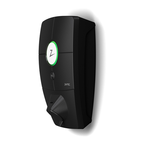
ZAPTEC Go User manual

Zaptec
Smart, small
and safe
Zaptec Go
Installation Manual


Zaptec Go
works with
any car
No matter what you drive or where
you’re going, Zaptec Go is the surest
way to power your journey. Built on
leading edge Norwegian green tech,
we’ve created a charger, that’s as
smart on the inside as it is simple
on the outside.

4
English
Important information
Before using or maintaining this product, it is important to
read the following safety instructions. Failure to follow and
apply all the instructions and procedures covered in this quick
guide will invalidate the guarantee and cause Zaptec Charger
AS and direct partners towaive all liability and claims for
compensation.
WARNING!
!Read through the instructions carefully and familiarize yourself with the equipment
before you start using it.
!This equipment must only be installed, repaired, and maintained by qualified
personnel. Repairs must be carried out by Zaptec or a pre-approved workshop.
!All applicable local, regional, and national laws and regulations must be followed
when installing, repairing, and maintaining the product.
!Do not install or use a product which is damaged in any way. See the information
in the chapter on Support and Repairs.
!Only use approved cabling for the installation.
!Do not insert foreign objects into the Type 2 socket.
!Do not use high-pressure washers to clean the charger station.
Follow the instructions in the chapter Storage and Maintenance.
!Avoid installing the charger in a location which is exposed to direct sunlight.
!Adapters are permissible – A conversion adapter from the charger outlet must only
be used if specified and approved by the vehicle manufacturer or charger producer
!Read the guarantee at zaptec.com/guarantee or contact Zaptec support
and request a copy.
5
English
Installing Zaptec Go
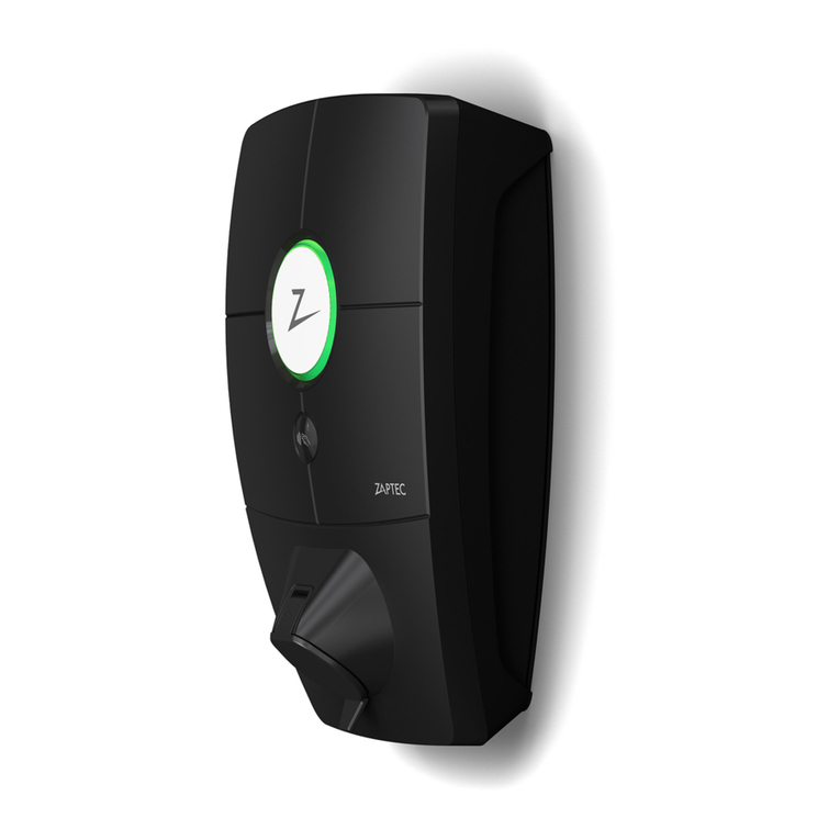
Status light
Type 2 socket
Charge card
authentication (RFID)
Zaptec
QR-code for installation
and activation
Scan here for the
installation video

6
English
Included in the box
3 x Cable seals 1 x Cable clamp
1 x Zaptec Go
User Manual Installation Manual
4 x T20 2 x T20 2 x T20
A
B
C
12-18 mm
cable diameter
8-14 mm
cable diameter

7
English
1. Remove the front cover
C
2. Mount the charging station
A
Recommended
height
0,9 m
Using the built-in spirit level, make sure it’s straight
and at the appropriate height.

8
English
3. Connect the power cable
Choose between three entry options
(top, back and bottom). Punch out the hole.
Carefully pull the terminal cover downwards
to remove it. Do not pull it towards you. The
cover is much easier to remove if you gently
press on the retaining tab (through the hole
by the configuration switch) while pulling
downwards.
The Zaptec Go needs an upstream circuit
breaker and dual pole RCD Type A
1
2
3
4. Secure cable
B
Prevent the cable from being dislocated by
using the cable clamp and screws
(max torque 3 Nm).
Use the cable seals to make the installation
water resistant.

9
English
5. Electrical connection
PE N L
PE N L PE L1 L2 PE L1 L2
Max
6 mm2
Max 12 mm
Click!
Connect all wires and firmly press down
all levers as illustrated. When the wires are
safely attached, replace the terminal cover
and turn on the circuit breaker.
Ferrules are optional.
Electrical wire dimensions

10
English
6. Configure charging station
To configure the Zaptec Go
with a Zaptec account
1. Open the Zaptec app and log in with
your Zaptec account
2. From the Home, tap the symbol
3. Select the “Install product” button
4. Scan the QR code located inside
the charger
5. Set the installation details (circuit breaker
size, maximum current and country)
6. If the settings are set correctly, tap
Finish
To configure the Zaptec Go
without a Zaptec account
1. Open the Zaptec App
2. Tap “Install a charging station”
3. Scan the QR code that is located
inside the charger
4. Set the installation details (circuit
breaker size, maximum current and
country)
5. If the settings are set correctly,
tap Finish
Zaptec
Before you begin, install the Zaptec App
from the App Store (iOS) or Google Play Store
(Android) and make sure the Bluetooth
on your phone is switched on.
When the Zaptec Go charger is switched on,
the status indicator will be orange.
This means it is ready to be configured.
Scan here for the
configuration video

11
English
To configure with the switch
Zaptec recommends that you use the
Zaptec App to configure the charger
whenever possible. However, you can
configure the charger without using
the app by using the switch. Note that
configuring this way will limit the
functionality of the charger:
• Circuit breaker value and available
power for charging is set to the same
value set by the switch
Switch configurations:
1 - 6 Amps
2 - 10 Amps
3 - 13 Amps
4 - 16 Amps
5 - 20 Amps
6 - 25 Amps
7 - 32 Amps
8 - Not in use
9 - Not in use
0 - Unconfigured or configured with App
0
5
1
2
3
4 6
7
8
9

12
English
7. Confirm status indicator
8. Mount the front cover
C
Configuration is complete when the circular
light (status indicator) changes from green
to white.
Secure and lock the front cover
(max torque 1 Nm).

13
English
9. That’s it!
If you have followed all the steps so far, then the Zaptec Go should be configured
and online. Make sure you hand over the User Manual to the owner of the charger.
!Remind the owner that they should create a Zaptec App account to activate
and connect to the Zaptec Go charger.

14
English
Load Balance = max 32A in total
to the chargers. NB: Equal value
40A 40A 40A
Circuit breaker and dual pole RCD
type A.
Must be equal in value
on installations with several Zaptec Go.
One circuit breaker and RCD
type A per Zaptec Go.
Integrated residual
current protection
RDC-DD (6mA DC)
according to IEC 62955
Integrated open PEN fault
detection according to BS
76712018 Amendment 12020
clause 722.411.4.1 (iv)
10. Install multiple chargers

15
English
No light
Updating firmware.
This normally takes a few minutes.
Error detected. Unplug vehicle
and restart the charging station.
Charger not configured.
Waiting for authorization
via Zaptec App or RFID.
Charging complete or charging is waiting
for scheduled start.
Charging.
The configuration is complete and the charger
is ready for the owner to start connecting and
activating it through their app.
Check charger power.
Purple
Red
Orange
Yellow
Green
Blue
White
11. Status light indicator

16
English
12. Support and repairs
If you discover an issue, please read the Troubleshooting section
before contacting Zaptec Support, or visit zaptec.com/support.

17
English
13. Troubleshooting
• Inadequate network coverage.
• 4G not activated on the charging station.
• 4G base station not supporting LTE -M.
The charging station
is not online (4G LTE-M)
Unable to connect
to Wi-Fi
Check that the SSID (network name) and the
password for the Wi-Fi are correct. If the network
is not visible, you must check that the Wi-Fi access
point uses 2.4 GHz (5 GHz is not supported), and
that it uses channels between 1 and 11.
If the SSID is hidden, you must enter the SSID and
password manually using “Other” in the network list.
Charging does
not start
• If the status indicator is yellow, this is because it is
waiting for authorization. Check if authorization
is enabled.
• If it is green, then check that the charger is scheduled
to charge* and has the correct current allocated in
the Zaptec portal**.
*In accordance with UK Smart Charging legislation, the
charger is supplied pre-configured with a schedule that
prevents charging between 8am and 11am and 4pm and
10pm on weekdays. During these times, charging will be
paused. The schedule can be disabled or amended by
using Configure product in the Zaptec App.
**Zaptec Portal is the brains behind our smart charging
infrastructure. It continuously monitors, balances, and
optimizes the load between the various charging stations.
The charging
is slow
The limitation on the charging effect will be
governed by the weakest of the following factors:
main power grid, the circuit breaker, charging cable,
On-Board Charger (OBC), Eco Mode (in selected
countries).
• Check the standalone current setting is set to the
correct value by repeating the «Install Zaptec Go
in the Zaptec App»
• Check the installation and charger power
management settings in the Zaptec Portal.
Read more on zendesk.zaptec.com
Zaptec Charger AS collects data from the product via the network.
More information on our privacy guidelines can be found at zaptec.com/privacy.

18
English
14. Storage and Maintenance
• Wipe down the charging station
with a damp cloth.
• Check that the charging connector
is free of all foreign materials.
• Check that the charging station
has no external, physical damage.
In the case of publicly accessible
installations, an annual inspection
must be carried out by qualified
personnel in accordance with
Norwegian legislation and regulations.
In the case of publicly accessible
installations, an annual inspection
must be carried out by qualified
personnel in accordance with local
legislation and regulations.
The product must be kept in a dry room with a stable
temperature. The following periodic maintenance is recommended:

19
English
15. Technical specifications
Mechanical and installation
PARAMETER TEST CONDITION MIN TYP MAX UNIT
Dimensions H: 242
W: 180
D: 75
mm
Weight 1.3 kg
Altitude 2000 m
Input cable cross
section
1.5 6 mm2
Input cable diameter 9 18.5 mm
Degree of protection IP54
Charging mode Mode 3, case B
Mechanical strength IK08
Pollution degree Installation environment 4
Support for ventilation According to
EN 61851-1 6.3.2.2
No
Access According to
EN 61851-1 5.4
Restricted and non-restricted
access

20
English
15. Technical specifications (continued)
General
PARAMETER TEST CONDITION MIN TYP MAX UNIT
Rated voltage (Un)
Phase-Neutral 207 230 253
V
Phase-Phase 360 400 440
Rated current (In) 32 A
Rated frequency 50 Hz
Standby power consumption 2 W
Ambient operating temperature -30 40 oC
Maximum charging power TN 1 phase @ 32 A 7.4 kW
Protection class I
Overvoltage category III
Connectivity
PROTOCOL SUPPORTED STANDARDS
4G LTE Cat M1
Wi-Fi 802.11b/g/n (2.4 GHz)
Bluetooth Bluetooth v4.2 (BR/EDR/BLE)
RFID
ISO/IEC 14443 A (Type A, 13.56 MHz)
ISO/IEC 15693 Type A (Mifare Classic, 13.56 MHz)
OCPP 1.6J Core (cloud to cloud)
Integrated energy meter
PARAMETER TEST CONDITION MIN TYP MAX UNIT
Accuracy Line voltage, current, and power factor +/-3 %
Other manuals for Go
8
Table of contents
Other ZAPTEC Automobile Accessories manuals

ZAPTEC
ZAPTEC Pro User manual

ZAPTEC
ZAPTEC Go User manual

ZAPTEC
ZAPTEC ZapCharger Portable C1 User manual

ZAPTEC
ZAPTEC Column Standard User manual

ZAPTEC
ZAPTEC Go User manual

ZAPTEC
ZAPTEC Go User manual

ZAPTEC
ZAPTEC Pro User manual

ZAPTEC
ZAPTEC Pro User manual

ZAPTEC
ZAPTEC Pro User manual

ZAPTEC
ZAPTEC Go User manual