Newport PM 500 Installation manual

-~
ARTISAN
®
~I
TECHNOLOGY
GROUP
Your definitive source
for
quality
pre-owned
equipment.
Artisan Technology
Group
Full-service,
independent
repair
center
with
experienced
engineers
and
technicians
on staff.
We
buy
your
excess,
underutilized,
and
idle
equipment
along
with
credit
for
buybacks
and
trade-ins
.
Custom
engineering
so
your
equipment
works
exactly as
you
specify.
•
Critical
and
expedited
services
•
Leasing
/
Rentals/
Demos
• In
stock/
Ready-to-ship
•
!TAR-certified
secure
asset
solutions
Expert
team
ITrust
guarantee
I
100%
satisfaction
All
tr
ademarks,
br
a
nd
names, a
nd
br
a
nd
s a
pp
earing here
in
are
th
e property of
th
e
ir
r
es
pecti
ve
ow
ner
s.
Find the Newport PM500-C at our website: Click HERE

i
PM500 SERIES
Operation and Command
Reference Manual
Artisan Technology Group - Quality Instrumentation ... Guaranteed | (888) 88-SOURCE | www.artisantg.com

ii Preface
Warranty
Newport Corporation warrants that this product will be free from defects in material
and workmanship and will comply with Newport’s published specifications at the
time of sale for a period of one year from date of shipment. If found to be defective
during the warranty period, the product will either be repaired or replaced at
Newport's option.
To exercise this warranty, write or call your local Newport office or representative,
or contact Newport headquarters in Irvine, California. You will be given prompt
assistance and return instructions. Send the product, freight prepaid, to the indicated
service facility. Repairs will be made and the instrument returned freight prepaid.
Repaired products are warranted for the remainder of the original warranty period or
90 days, whichever first occurs.
Limitation of Warranty
The above warranties do not apply to products which have been repaired or modified
without Newport’s written approval, or products subjected to unusual physical,
thermal or electrical stress, improper installation, misuse, abuse, accident or
negligence in use, storage, transportation or handling. This warranty also does not
apply to fuses, batteries, or damage from battery leakage.
THIS WARRANTY IS IN LIEU OF ALL OTHER WARRANTIES, EXPRESSED OR
IMPLIED, INCLUDING ANY IMPLIED WARRANTY OF MERCHANTABILITY OR
FITNESS FOR A PARTICULAR USE. NEWPORT CORPORATION SHALL NOT BE
LIABLE FOR ANY INDIRECT, SPECIAL, OR CONSEQUENTIAL DAMAGES
RESULTING FROM THE PURCHASE OR USE OF ITS PRODUCTS.
Trademarks
Windows is a registered trademark of Microsoft Corporation. LabVIEW and
LabWindows are trademarks of National Instruments Corporation.
Copyright 2001 by Newport Corporation, Irvine, CA. All rights reserved. No part of this
manual may be reproduced or copied without the prior written approval of Newport
Corporation.
This manual has been provided for information only and product specifications are subject to
change without notice. Any change will be reflected in future printings.
©2001 Newport Corporation
1791 Deere Ave.
Irvine, CA 92606
(800) 222-6440
P/N 22519-01, Rev. A
Artisan Technology Group - Quality Instrumentation ... Guaranteed | (888) 88-SOURCE | www.artisantg.com

Preface iii
Confidentiality & Proprietary Rights
Reservation of Title:
The Newport programs and all materials furnished or produced in connection
with them ("Related Materials") contain trade secrets of Newport and are for
use only in the manner expressly permitted. Newport claims and reserves all
rights and benefits afforded under law in the Programs provided by Newport
Corporation.
Newport shall retain full ownership of Intellectual Property Rights in and to
all development, process, align or assembly technologies developed and other
derivative work that may be developed by Newport. Customer shall not
challenge, or cause any third party to challenge the rights of Newport.
Preservation of Secrecy and Confidentiality and Restrictions to Access:
Customer shall protect the Newport Programs and Related Materials as trade
secrets of Newport, and shall devote its best efforts to ensure that all its
personnel protect the Newport Programs as trade secrets of Newport
Corporation. Customer shall not at any time disclose Newport's trade secrets
to any other person, firm, organization, or employee that does not need
(consistent with Customer's right of use hereunder) to obtain access to the
Newport Programs and Related Materials. These restrictions shall not apply
to information (1) generally known to the public or obtainable from public
sources; (2) readily apparent from the keyboard operations, visual display, or
output reports of the Programs; 93) previously in the possession of Customer
or subsequently developed or acquired without reliance on the Newport
Programs; or (4) approved by Newport for release without restriction.
Service Information
This section contains information regarding factory service for the PM500
System. The user should not attempt any maintenance or service of the
system or optional equipment beyond the procedures outlined in this manual.
Any problem that cannot be resolved should be referred to Newport
Corporation.
Artisan Technology Group - Quality Instrumentation ... Guaranteed | (888) 88-SOURCE | www.artisantg.com

iv Preface
Technical Support Contacts
Newport Corporation Service Department.
1791 Deere Ave.
Irvine, CA 92606
Telephone: (800) 222-6440
Newport Corporation RMA Procedures
Each defective part must have an RMA number assigned by a Newport
representative. The serial number of the damaged component must be
provided to the Newport representative. Please refer to Appendix G of this
manual for complete RMA procedure.
Packaging
Stages must be packaged in their original boxes and the stage locking tabs
must be installed prior to shipping. There is a written procedure for removing,
packaging, and shipping Newport stages. Please refer to Appendix F of this
manual.
Artisan Technology Group - Quality Instrumentation ... Guaranteed | (888) 88-SOURCE | www.artisantg.com

Preface v
Table of Contents
Warranty.................................................................................................ii
Technical Support Contacts .................................................................. iv
Table of Contents................................................................................... v
List of Figures.......................................................................................xi
1Introduction 13
1.1 Scope of the Manual................................................................... 13
1.2 Manual Conventions................................................................... 14
1.2.1 Keys, Buttons and Icons..................................................14
1.2.2 Key Operation .................................................................14
1.2.3 User Input........................................................................14
1.2.4 The Display .....................................................................14
2Safety Precautions 15
2.1 Definitions and Symbols ............................................................ 15
2.1.1 General Warning or Caution ...........................................15
2.1.2 Grounding........................................................................15
2.1.3 Electric Shock..................................................................15
2.2 Terminology............................................................................... 16
2.3 Warnings and Cautions............................................................... 16
2.4 Safety Considerations................................................................. 17
3Getting Started 19
3.1 Outline of Section 1.................................................................... 19
3.2 Unpacking and Handling............................................................ 20
3.3 Inspection and Damage .............................................................. 21
3.4 Linear Stage Shipping Tab Removal (Except PM500-1A, 1L, 1V) .. 22
4Mounting Positioners and Actuators 23
4.1 Outline of Section 4.................................................................... 23
4.2 Preparing the Mounting Surface................................................. 24
4.3 Vertical Stage Mounting............................................................. 24
4.4 Mounting PM500-1A Actuators................................................. 25
4.5 Mounting PM500-1A Linear Stages .......................................... 25
4.6 Mounting PM500 Linear Stages (Except PM500-1L) ............... 26
4.7 Mounting PM500 Rotary Stages................................................ 28
5Device Controller Interconnection 29
5.1 Outline of Section 5.................................................................... 29
5.2 Matching Devices and Axis Cards............................................. 30
5.3 Rack Mounting........................................................................... 30
5.4 Back Panel Connectors............................................................... 31
5.5 Connecting Cables...................................................................... 32
5.5.1 Cable types ......................................................................32
Artisan Technology Group - Quality Instrumentation ... Guaranteed | (888) 88-SOURCE | www.artisantg.com

vi Preface
5.5.2 Cable routing...................................................................32
5.6 Remote Motor Shutdown Connector.......................................... 33
5.7 Cooling....................................................................................... 33
6Attaching Loads to Positioners 35
6.1 Outline of Section 6.................................................................... 35
6.2 Effect of Vibrations.................................................................... 36
6.3 Constructing fixtures .................................................................. 36
6.3.1 Rigidity............................................................................36
6.3.2 Weight .............................................................................37
6.3.3 Locating the load.............................................................37
6.4 Attaching Cables and Feeds ....................................................... 38
6.5 Vertical Stages............................................................................ 39
6.6 Pneumatic Load Compensation Piston....................................... 41
6.6.1 Regulator compensation adjustment................................41
6.6.2 Routing of air supply line................................................42
7Operation 43
7.1 Outline of Section 7.................................................................... 43
7.2 Choosing an Interface................................................................. 43
7.2.1 RS-232.............................................................................43
7.2.2 GPIB................................................................................44
8PM500-K6 Remote Control Console 45
8.1 Outline of Section 8.................................................................... 45
8.2 Connection.................................................................................. 46
8.3 Operating Modes ........................................................................ 46
8.3.1 Execute mode operation..................................................47
8.3.2 Menu mode operation......................................................47
8.4 Menu Key Functions .................................................................. 48
8.4.1 Main Menu ......................................................................48
8.4.2 Setup Menu......................................................................49
8.5 Controlling the PM500-K6 via RS-232/GPIB ........................... 50
9RS-232 Computer Interface 51
9.1 Outline of Section 9.................................................................... 51
9.2 Setup and Operation................................................................... 51
9.2.1 What you’ll need .............................................................51
9.2.2 Setting the RS-232 parameters........................................52
9.2.3 Configuring for RS-232 communications.......................52
9.2.4 RS-232 interface specifications.......................................53
9.2.5 Description of the PM500 RS-232 port...........................53
9.2.6 RS-232 cable length restrictions......................................54
9.2.7 Sample RS-232 cable configurations ..............................54
9.3 RS-232 Operation....................................................................... 55
Artisan Technology Group - Quality Instrumentation ... Guaranteed | (888) 88-SOURCE | www.artisantg.com

Preface vii
9.3.1 RS-232 Handshaking Modes...........................................55
9.3.2 Synchronous RS-232 Interfacing ....................................56
9.3.3 RS-232 default configuration interfacing........................57
9.3.4 Disabling RS-232 responses............................................58
10 RS-232 Quick Start 59
10.1 Outline of Section 10.................................................................. 59
10.2 PM500-C6 configuration for RS-232 (Quick Start)................... 59
10.2.1 What you’ll need .............................................................59
10.2.2 Verifying communication................................................61
11 GRIP (IEEE-488) Computer Interface 63
11.1 Outline of Section 11.................................................................. 63
11.2 Setup and Operation................................................................... 63
11.2.1 What you’ll need .............................................................63
11.2.2 Setting the GPIB address.................................................64
11.3 GPIB Quick Start with Interactive Control Software................. 65
11.4 4.2.1.2 IEEE-488 Operation....................................................... 66
12 Motion Programming 69
12.1 Outline of Section 12.................................................................. 69
12.2 Command Types and Their Responses ...................................... 69
12.2.1 Device Independent commands.......................................69
12.2.2 Device dependent commands..........................................69
12.2.3Command Types.........................................................70
12.2.4 Motion Response.............................................................70
12.2.5 Read/Status Commands...................................................71
12.2.6 Read response formats.....................................................72
12.2.7 Using hexadecimal numbers............................................72
12.2.8 Parametric Data Commands............................................73
12.2.9 Command Error Messages ..............................................73
12.3 Command Syntax ....................................................................... 74
12.3.1 For system or motion commands: ...................................74
12.3.2 For multiple system or motion commands......................74
12.3.3 For Read/Status and Queries...........................................74
12.3.4 Syntax Definitions...........................................................74
12.3.5 Numeric Formats.............................................................76
12.4 Command Status Characters....................................................... 77
12.5 GPIB Basics................................................................................ 78
12.5.1 Programming the PM500 ................................................78
12.5.2 Service Request...............................................................78
12.6 SRQ Assertion/Serial Polling methods ...................................... 80
12.6.1 Serial Program Execution (Wait for SRQ/RSQ).............80
Artisan Technology Group - Quality Instrumentation ... Guaranteed | (888) 88-SOURCE | www.artisantg.com

viii Preface
12.6.2 Parallel Program Execution (Serial Poll) ........................80
12.7 Serial Polling .............................................................................. 80
13 Programming the PM500-C6 81
13.1 Outline of Section 13.................................................................. 81
13.2 System Software of PM500 Controllers..................................... 82
13.3 Checking Your System Software Version.................................. 82
13.4 The Difference Between the Modes........................................... 83
13.5 Status and Error Report Flowchart for the PM500..................... 84
13.6 Error Handling............................................................................ 85
13.6.1 Initializing the PM500 (SCUM1 or 6axis controllers)....85
13.6.2 General communication and ‘handshaking’ with PM500
Program Flowchart (under SCUM1) operation mode.....86
13.6.3 Simultaneous Preset Motions..........................................87
13.7 The Motion Profile And Related Motion Commands................ 89
13.8 Motion Speed Loops................................................................... 89
13.9 Motion Device Dependent commands & PM500 devices ......... 90
13.9.1 Linear motion device commands.....................................90
13.9.2 Rotary motion device commands....................................91
13.9.3 Vertical motion device commands..................................93
13.10Essential Motion Commands...................................................... 94
14 Command Index (by Type) 95
15 Command Index (Alphabetical) 99
16 Command Reference 105
17 Functional Description & Specifications 267
17.1 Outline of Section 17................................................................ 267
17.2 Controller.................................................................................. 268
17.2.1 Power supply/motherboard............................................270
17.3 Controller Board....................................................................... 271
17.4 Axis Boards .............................................................................. 273
17.5 Motion Devices ........................................................................ 276
17.5.1 Motion device specifications.........................................278
18 Maintenance 279
18.1 Outline of Section 18................................................................ 279
18.2 Auto-Zero Self Calibration....................................................... 280
18.3 Stages and Actuators- Maintenance ......................................... 280
18.4 Motors- Maintenance................................................................ 281
18.5 Leadscrew- Maintenance.......................................................... 281
18.6 Crossed-Roller Bearings- Maintenance.................................... 282
18.7 Encoders- Maintenance ............................................................ 282
18.8 Cables- Maintenance ................................................................ 282
Artisan Technology Group - Quality Instrumentation ... Guaranteed | (888) 88-SOURCE | www.artisantg.com

Preface ix
18.9 Controller- Maintenance........................................................... 282
18.10Maintenance Schedule.............................................................. 283
19 Service 285
19.1 Outline of Section 19................................................................ 285
19.2 Removing and Installing Axis Boards...................................... 286
19.2.1 Axis card removal..........................................................287
19.2.2 Axis card installation.....................................................288
19.3 Removing and Installing the Controller Board ........................ 289
19.3.1 Controller board installation..........................................291
19.4 Upgrading System Firmware.................................................... 292
19.4.1 What you’ll need ...........................................................293
19.4.2 For axis card firmware upgrades...................................293
19.4.3 For controller card firmware upgrades..........................293
19.4.4 Firmware upgrade procedure.........................................293
19.5 System Initialization................................................................. 294
19.6 Troubleshooting........................................................................ 295
19.6.1 LED diagnostics ............................................................295
19.6.2 Motherboard/power supply ...........................................295
19.6.3 Controller board.............................................................296
19.6.4 Axis boards....................................................................297
19.7 Troubleshooting Tables............................................................ 298
20 Appendix A 307
20.1 Outline of Appendix A............................................................. 307
20.2 Cabling and Communications .................................................. 307
21 Appendix B 309
21.1 Outline of Appendix B ............................................................. 309
21.2 Cleanroom Compatibility and Preparation............................... 309
21.3 Cleanroom Compatibility and Preparation............................... 310
22 Appendix C 311
22.1 Outline of Appendix C ............................................................. 311
22.2 Vacuum Compatabilities .......................................................... 311
23 Appendix D 313
23.1 Outline of Appendix D............................................................. 313
23.2 Memory capacities & capabilities of the controller ................. 313
23.2.1 SBC (Motherboard).......................................................313
23.2.2 Axis Cards.....................................................................314
24 Appendix E 315
24.1 Motion Trajectory Specifications............................................. 315
24.2 Motion Performance Summary ................................................ 316
Artisan Technology Group - Quality Instrumentation ... Guaranteed | (888) 88-SOURCE | www.artisantg.com

x Preface
25 Appendix F 317
25.1 Outline of Appendix F.............................................................. 317
25.2 Packaging your PM500 System................................................ 317
25.3 Packaging your PM500-C6 Controllers ................................... 318
26 Appendix G 319
26.1 Warranty and Service Policy.................................................... 319
27 Appendix H 321
27.1 Service Form ............................................................................ 321
28 Appendix I 323
28.1 System Settings ........................................................................ 323
Index 325
Artisan Technology Group - Quality Instrumentation ... Guaranteed | (888) 88-SOURCE | www.artisantg.com

Preface xi
List of Figures
Figure 1: General Warning or Caution Symbol......................................... 15
Figure 2: Grounding Symbol ..................................................................... 15
Figure 3: Electrical Shock Symbol ............................................................ 15
Figure 4: P500 Stage.................................................................................. 20
Figure 5: PM500 Stage Shipping Tab........................................................ 20
Figure 6: PM500 Stage Shipping Tab........................................................ 21
Figure 7: Removing the shipping tab before using the stage..................... 22
Figure 8: Considerations for mounting motion devices............................. 23
Figure 9: Do not mount standard Linear Stages vertically ........................ 24
Figure 10: Mounting PM500-1 Linear Stage............................................... 26
Figure 11: Exploded view of linear stage. ................................................... 27
Figure 12: PM500 Rotary Stages are sensitive to high-torque loads........... 28
Figure 13: Assignment of axes change. ....................................................... 30
Figure 14: Exploded view of attachment of rack ears on controller............ 30
Figure 15: Rear view of the PM500-C 6-axis controller. ............................ 31
Figure 16: Placeing loads............................................................................. 36
Figure 17: Calculating cantilevered loads.................................................... 37
Figure 18: Attaching cables and feeds........................................................ 38
Figure 19: Placing loads or tightening screws to fasten loads..................... 38
Figure 20: A typical installation of a Z-bracket........................................... 39
Figure 21: Mounting to another stage.......................................................... 40
Figure 22: Routing of air supply line........................................................... 42
Figure 23: DIP switch location in PM500-C6 ............................................. 52
Figure 24: Changing the RS-232 parameters............................................... 52
Figure 25: Back panel of the PM500 controller........................................... 53
Figure 26: DIP switch location in PM500-C6 ............................................. 59
Figure 27: The RS-232 parameters are changed via S1 and S2 switch . ..... 60
Figure 28: Command to complete signaling and echoing............................ 60
Figure 29: PM500 response to firmware version query............................... 61
Figure 30: DIP switch location in PM500-C6 ............................................. 64
Figure 31: The GPIB address is changed via S1 and S2 switch banks........ 64
Figure 32: Flowchart: Status and error reporting registers of the PM 500. . 84
Figure 33: Flowchart: An initialization procedure for the PM 500. ............ 86
Figure 34: A general handshaking and communication method.................. 87
Figure 35: PM500’s simultaneous preset motion. ....................................... 88
Figure 36: Trapezoidal move profile with corresponding commands......... 89
Figure 37: Setting the LSIZE ...................................................................... 90
Figure 38: Linear motion device commands forPM500 Linear Stages....... 91
Figure 39: PM500-360/A Rotary stages. ..................................................... 92
Figure 40: PM500-V1 Vertical stages. ........................................................ 93
Figure 41: Top view of Model PM500 Controller..................................... 268
Figure 42: Rear view of Model PM500 Controller.................................... 268
Artisan Technology Group - Quality Instrumentation ... Guaranteed | (888) 88-SOURCE | www.artisantg.com

xii Preface
Figure 43: PM500 Controller functional elements. ................................... 269
Figure 44: Motherboard. ............................................................................ 270
Figure 45: Power supply/Motherboard functional elements...................... 270
Figure 46: Controller board........................................................................ 271
Figure 47: High Resolution Axis Board. ................................................... 273
Figure 48: Figure 16.8: Axis board schematic........................................... 273
Figure 49: Schematic of axis board velocity loop...................................... 274
Figure 50: Schematic of axis board position loop...................................... 275
Figure 51: Axis board sine/cosine signals.................................................. 276
Figure 52: Read head. ................................................................................ 277
Figure 53: The retaining bar removal from the controller......................... 287
Figure 54: Cable nuts removal................................................................... 288
Figure 55: The controller board status LEDs............................................. 288
Figure 56: The retaining bar removal ........................................................ 290
Figure 57: The controller board status....................................................... 291
Figure 58: Proper PROM placement in socket and location on card......... 294
Figure 59: D-style 25-pin axis cable connector to rear panel. ................... 308
Figure 60: Axis cable................................................................................. 308
Figure 61: The trajectory error effects of pitch, roll, and yaw................... 315
Figure 62: The typical factory packaging for PM500 devices................... 317
List of Tables
Table 1: A graphical representation of the PM500 SRQ register............. 79
Table 2: Basic Troubleshooting.............................................................. 299
Table 3: Check Power and Lights........................................................... 299
Table 4: Communication Link(s) Troubleshooting................................ 301
Table 5: Check Servo Action and Axis Response.................................. 303
Table 6: Check Marginal Performance/Positioning ............................... 304
Table 7: Check Remote Console (PM500-K)......................................... 305
Artisan Technology Group - Quality Instrumentation ... Guaranteed | (888) 88-SOURCE | www.artisantg.com

13
1 Introduction
1.1 Scope of the Manual
Welcome to the PM500 Series Operations and Command Reference
Manual.
This manual provides descriptions, operating procedures, and service
requirements for the PM500 Linear and Rotary Stages.
Safety considerations, conventions and definitions are provided in Section
2, Safety Considerations.
Procedures for unpacking the equipment, inspection for damage are
provided in Section 3 - Getting Started. Mounting requirements,
descriptions of controls and indicators, computer interface, motion
programming, setup procedures, and service and maintenance are provided
in sections 1 through 19.
The Following Information Is Provided In The Appendices:
•Appendix A – Cabling And Communications
•Appendix B – Clean Room Compatibility And Outgassing
•Appendix C – Vacuum Compatibilities
•Appendix D – Memory Capabilities
•Appendix E – Motion Specifications
•Appendix F – Packaging
•Appendix G – Warranty Return
•Appendix H– Service Form
•Appendix I – System Settings
Artisan Technology Group - Quality Instrumentation ... Guaranteed | (888) 88-SOURCE | www.artisantg.com

14 Introduction
1.2 Manual Conventions
The following conventions and standards will be used in this manual.
1.2.1 Keys, Buttons and Icons
Computer keyboard keys and onscreen buttons and icons are used in the text
to describe many user operations. The key-top symbol as it appears on the
keyboard, the button or icon name is represented in boldface type. For
example: Ctrl is used for the Control key or Manual Operation button.
1.2.2 Key Operation
Some operations require simultaneously use of two or more keys. Such
operations are identified by the top symbols on the key separated by a plus
(+) sign. For example, Ctrl + Pause (Break) means hold down the Ctrl key
and at the same time press Pause (Break). If three keys are used, hold down
the first two and at the same time press the third.
1.2.3 User Input
Text that is required to be typed in, will be shown in the boldface type courier
(new) font as shown below:
DISKCOPY A: B:
1.2.4 The Display
Text generated by the computer that appears on its display is presented in the
typeface courier (new) font as shown below:
FORMAT complete
Artisan Technology Group - Quality Instrumentation ... Guaranteed | (888) 88-SOURCE | www.artisantg.com

15
2 Safety Precautions
2.1 Definitions and Symbols
The following terms and symbols are used in this documentation and also
appear on PM500 Series Products where safety-related issues occur.
2.1.1 General Warning or Caution
Figure 1: General Warning or Caution Symbol
The Exclamation Symbol in the figure above appears in Warning and Caution
tables throughout this document. This symbol designates an area where
personal injury or damage to the equipment is possible.
2.1.2 Grounding
Figure 2: Grounding Symbol
The Grounding Symbol in the figure above appears on labels affixed to the
PM500 Series Products, and this symbol identifies terminal which is intended
for connection to an external (ground) conductor for protection against
electric shock in case of a fault, or the terminal of a protective earth (ground)
electrode. Any mishandling could result in irreparable damage to the
equipment, and personal injury or death.
2.1.3 Electric Shock
Figure 3: Electrical Shock Symbol
The Electrical Shock Symbol in the figure above appears on labels affixed to
the PM500 Series Products, and this symbol indicates a hazard arising from
dangerous voltage. Any mishandling could result in irreparable damage to
the equipment, and personal injury or death.
Artisan Technology Group - Quality Instrumentation ... Guaranteed | (888) 88-SOURCE | www.artisantg.com

16 Safety Precautions
2.2 Terminology
The following is a brief description of the terms specific to PM500 Series
Controller and Stages.
Axis – a logical name for a stage/positioner/ motion device
Encoder – a displacement measuring device, term usually used for
both linear and rotary models.
Fiducial (position) – the unique point in space that can be
accurately found by an axis, also called origin.
Jog – a motion of undetermined-length, initiated manually
Motion device – electro-mechanical equipment. Used
interchangeably with stage and positioner.
Move – a motion to a destination
Positioner – used interchangeably with stage and motion device
Stage – used interchangeably with motion device and positioner
2.3 Warnings and Cautions
The following are definitions of the Warnings, Cautions and Notes that are
used throughout this manual to call your attention to important information
regarding your safety, the safety and preservation of your equipment or an
important tip.
WARNING
Situation has the potential to cause bodily harm or death.
CAUTION
Situation has the potential to cause damage to property or
equipment.
NOTE
Additional information the user or operator should consider.
Artisan Technology Group - Quality Instrumentation ... Guaranteed | (888) 88-SOURCE | www.artisantg.com

Safety Precautions 17
2.4 Safety Considerations
The following general safety precautions must be observed during all phases
of operations of this equipment. Failure to comply with these precautions or
with specific warnings elsewhere in this manual violates safety standards of
design, manufacture, and intended use of the equipment.
Disconnect or do not plug in the power cord in the following circumstances:
•If the power cord or any other attached cables are frayed or damaged.
•If the power plug or receptacle is damaged.
•If the unit is exposed to rain or excessive moisture, or liquids are
spilled on it.
•If the unit has been dropped or the case is damaged.
•If you suspect service or repair is required.
•When you clean the case.
To protect the equipment from damage and avoid hazardous situations,
follow these recommendations:
•Do not make modifications or parts substitutions.
•Return equipment to Newport Corporation for service and repair.
•Do not touch, directly or with other objects, live circuits inside the unit.
•Keep air vents free of dirt and dust.
•Do not block air vents.
•Keep liquids away from unit.
•Do not operate the equipment in an environment with humidity levels
(<10% and >90% humidity).
WARNING
All attachment plug receptacles in the vicinity of this unit are to be
of the grounding type and properly polarized. Contact an
electrician to check faulty or questionable receptacles.
WARNING
This product is equipped with a 3-wire grounding type plug. Any
interruption of the grounding connection can create an electric
shock hazard. If you are unable to insert the plug into your wall
plug receptacle, contact an electrician to perform the necessary
alterations to assure that the green (green-yellow) wire is attached
to earth ground.
Artisan Technology Group - Quality Instrumentation ... Guaranteed | (888) 88-SOURCE | www.artisantg.com

18 Safety Precautions
WARNING
This product operates with voltages that can be lethal. Pushing
objects of any kind into cabinet slots or holes, or spilling any
liquid on the product, may touch hazardous voltage points or
short out parts.
WARNING
When opening or removing covers observe the following
precautions:
•Turn power OFF and unplug the unit from its power source
•Remove jewelry from hands and wrists
•Use insulated hand tools only
•Maintain grounding
WARNING
To protect operating and servicing personnel, this instrument is
supplied with a three-prong power receptacle. The center prong
of the receptacle connects the instrument’s chassis, cabinet
and panels to earth ground when used with a properly wired
three-conductor outlet and cable. Improperly grounded
equipment can result in hazardous electrical potentials.
Artisan Technology Group - Quality Instrumentation ... Guaranteed | (888) 88-SOURCE | www.artisantg.com

19
3 Getting Started
3.1 Outline of Section 1
The following topics are covered in this section:
•Unpacking and inspection of the system
•Handling of motion devices
For additional setup and operation information for optional features, refer to
the appropriate sections:
OPTION SECTION
Vertical stages 6.5
Counter balance 6.5
Adding stages to an existing controller 19.3
Updating system firmware 19.4
WARNING
Read this entire section before assembling your system for the
first time. System performance depends on many factors,
including stage mounting and load attachment. Damage to the
system can occur if devices are not connected or operated
correctly.
Artisan Technology Group - Quality Instrumentation ... Guaranteed | (888) 88-SOURCE | www.artisantg.com
Other manuals for PM 500
1
Table of contents
Other Newport Industrial Equipment manuals
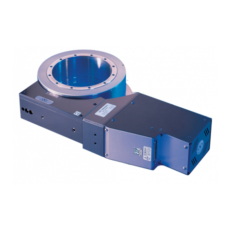
Newport
Newport RV User manual
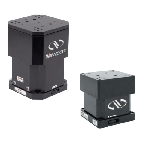
Newport
Newport GTS-V Series User manual

Newport
Newport New Focus 8892 User manual
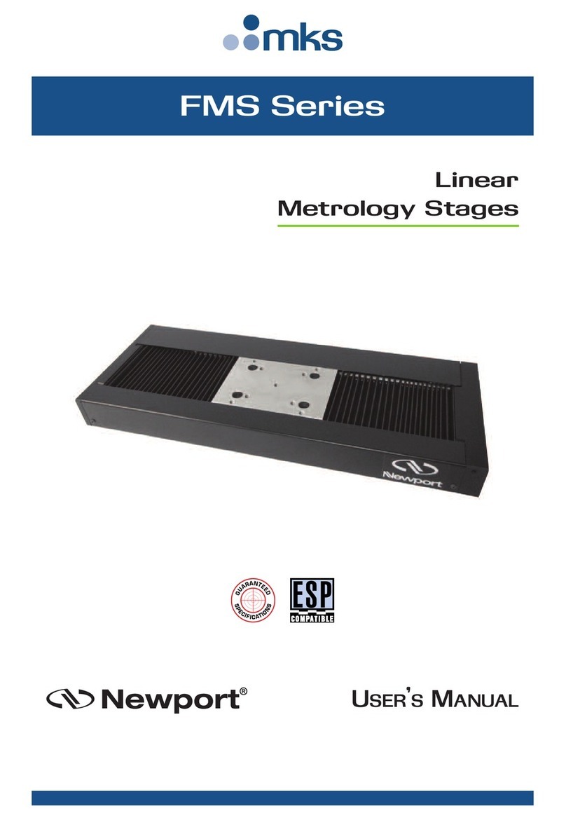
Newport
Newport FMS Series User manual

Newport
Newport TSP Series User manual
Newport
Newport ORIEL Instruments Cornerstone 260 User manual
Newport
Newport GTS30V User manual
Newport
Newport IDL165-LM Series User manual

Newport
Newport UTM Series User manual
