MMM Group ecocell 22 User manual

Instructions for use
Laboratory drying ovens and incubators
line Standard
ECOCELL 22, 55, 111, 222, 404, 707
DUROCELL 22, 55, 111, 222
VENTICELL 22, 55, 111, 222, 222/2, 404,
404/2, 707, 707/2
INCUCELL 22, 55, 111, 222, 404, 707
INCUCELL V 22, 55, 111, 222, 404, 707
LSI-S_np_en_1309_mmm_V2.10_B2V

Congratulations on obtaining a new temperature cabinet, designed for uniform tempering of various
materials by hot air at a selectable temperature and a selectable time mode in laboratories. There is an
air ap installed that enables wet material drying. The temperature course is controlled by an advanced
microprocessor (Fuzzy logic) with a digital display and a temperature sensor PT 100. This system
ensures high accuracy of temperature regulation and tempering process reliability.
The units meet technical and legislative requirements and they are designed according to respective
EN standards. The units are made of high quality materials by using the latest technology. Each piece
undergoes a careful output control.
Provided you will follow the instructions mentioned here the unit becomes your reliable and powerful
partner.
Now these advantages will be available just for you. This unit will help to solve your everyday problems
and it will become powerful assistant for you. This unit is very easy to use, nevertheless, we recommend
you to read the Operating instructions carefully so that you could use all advantages of this unit and
obtain complete knowledge for its optimal use.

CONTENTS:
6. 9. 2013
1 GENERAL................................................................................................................................3
1.1 PurPose and use............................................................................................................................3
2 IMPORTANT INSTRUCTIONS...................................................................................................3
2.1 unPacking, checking and transPort..............................................................................................3
2.2 Before installation........................................................................................................................3
2.3 useful sPace..................................................................................................................................5
3 DESCRIPTION OF THE UNIT....................................................................................................5
3.1 general view.................................................................................................................................5
3.2 Power connection and connectors..............................................................................................6
3.3 control Panel...............................................................................................................................7
4 FUNCTION AND OPERATING................................................................................................7
4.1 starting ans switching-off............................................................................................................7
4.2 setting-uP the required values of temPerature, time-delayed switching-off, numBer of cycles,
time-delayed Program start ..........................................................................................................8
4.3 user menu.....................................................................................................................................9
4.4 alarm function..............................................................................................................................9
4.5 Protocol Printing.........................................................................................................................9
4.5.1
installation and setting of the Printer........................
...........................................................10
4.5.2
Printing................................................................................................................................10
4.6 safety system function and setting.............................................................................................10
4.6.1
change of maximum and minimum values........................................................................................11
4.6.2
suPervisory circuit diagram function.........................................................................................11
4.6.3
temPerature limits of the units.....................................................................................................11
4.6.4
checking the safety relay function.........................................................................................11
4.6.5
checking the correct activity of the safety system................................................................11
4.7 list of error messages..............................................................................................................12
4.7.1
not disPlayed errors..................................................................................................................13
4.8 adjusting and function of the air flaP...................................................................................13
4.9 exchanging the door sealing and adjusting the door.............................................................14
5 PARAMETERS OF THE UNIT.................................................................................................16
5.1 electric connections...................................................................................................................17
6CLEANINGAND DECONTAMINATION OF THE UNIT.................................................................17
7 MAINTENANCE......................................................................................................................18
8 WARRANTY AND SERVICE....................................................................................................18
9 TRANSPORT AND STORAGE.................................................................................................18
10 THE WAY OF LIQUIDATION OF PACKAGE AND DISCARDED UNIT................................19
11 OPTIONAL EQUIPMENT...........................................................................................................19
11.1 door with window and inner lighting (excePt ic, icv excePt ic, icv for all the tyPes
of the volume of
22)...................................................................................................................19
11.2 access Ports of diameter
25, 50, 100
mm.......................................................................................20
11.3 lockaBle door.............................................................................................................................20
11.4 left door version......................................................................................................................20
11.5 flexiBle Pt
100
sensor.................................................................................................................20
11.6 suPPortive sw for Pc...............................................................................................................20

11.6.1 recording sw - warmcomm - for Pc under windows..................................................................20
11.6.2 recording Printing sw - Printer archiv - for Pc under windows................................................20
11.7 hePa filter....................................................................................................................................20
11.7.1 instalation of hePa filter, filter dimensions, function and filtration characteristic
of the air filter.............................................................................................................................21
11.8 two-door Passing - through version..............................................................................................21
11.8.1 venticell
222/2
- installation data....................................................................................................22
11.8.2 venticell
404/2
- installation data.................................................................................................22
11.8.3 venticell
707/2
- installation data..................................................................................................23
11.8.4
douBle-door through version with automatic door Blocking.......................................................
24
11.8.5
door Blocking errors................................................................................................................
24
11.9 anti-dry modification for cultivating mediums and tissue cultures.............................................25
11.10 no-Potential contact - alarm........................................................................................................25
12 EMERGENCY DOOR OPENING.............................................................................................25
APPENDICES:
EC - DECLARATION OF CONFORMITY

1
general
The electrically heated ovens/incubators
are designed for laboratories, especially for
tempering of various materials by hot air at
adjustable temperature and optional time mode.
An air ap enables to dry wet materials.
An advanced modern microprocessor (Fuzzy
- logic) with a digital display and a PT 100
controls the temperature course. This system
provides high accuracy of temperature control
and reliability of the tempering process. The
second independent digital safety system
ensures, together with the second independent
temperature sensor, the control and safety of the
tempering process for the whole device life.
These devices meet all legislative requirements
and are designed according to respective EN
standards – see Conformity Declaration. They
are made of high-grade materials by using the
latest technology.
Each unit undergoes a careful output control.
1.1
PURPOSE AND USE
ECOCELL (EC) is intended for tempering of
materials by hot air with natural circulation. The
units are designed for temperatures up to
250 °C, optionally up to 300 °C. Compared
with VC units they are characterized by quiet
operation and lower consumption of electrical
energy.
DUROCELL (DC) serves for hot-air tempering
with natural circulation (use for the following
procedures: Acid hydrolysis, extraction of non-
ammable substances, thermal decomposition
in closed vessels). The devices are intended for
temperatures up to 125 °C. The inner surfaces of
the chamber are covered with an EPOLON layer
which protects the chamber against corrosive
action of acids in form of liquids or vapours in case
of their accidental leakage from closed vessels.
For other important information see the chapter
Before Putting into Operation.
VENTICELL (VC) is intended for tempering of
materials by hot air with forced air circulation
by means of a fan. The ovens are designed for
temperatures up to 250 °C, optionally up to 300 °C.
INCUCELL (IC, ICV) serves as an incubator or
for cell cultivation in microbiological laboratories
(see chapter Optional equipment; Anti-dry
modication of cultivating mediums and tissue
cultures). The units are designed for temperatures
up to 70 °C optionally up to 100 °C. A quiet
operation is characteristic for the version IC
(without a fan), more accurate temperature
regulation with small deviations is characteristic
for the version ICV (with ventilator).
2
important
instructions
2.1
UNPACKING, CHECKING AND
TRANSPORT
Please check after unpacking whether the
unit and its accessories are complete and not
damaged. An eventual damage has to be reported
to the transporting company immediately. During
the manipulation – in case of lifting the cabinet
etc. – the unit must not be held by the rail or
door. The units of volumes 404 and 707 shall be
lifted by means of supplied hooks; the casters
are designed for local moving only, not for longer
transport. A standard delivery consists of a
temperature cabinet and two sieves, three chip
cards formatted for program download (marked
Programs – empty) and one special operations
card (SO).
Attention: If an SO card is used for a program
download, its original function will be cancelled.
2.2
bEFORE INSTALLATION
● Please read carefully the Operating
Instructions before starting the work
with the unit!
● Install the instrument by plugging the power
cord to a line voltage socket. The specied
parameters of the connection are described
in chapter 5.1 - Electrical Connection.
● At temperatures of above 100 °C the inner
chamber surface becomes yellowish. This
coloration is neither the material nor the
device defect.
After the rst starting of the unit the heating
elements and insulation start to be baked
with a typical smell; after a few operation
cycles this smell disappears, nevertheless,
it is suitable, during the insulation baking at
a temperature above 100 °C, to provide a
sufcient air exchange (e.g. by ventilation
or exhaustion).
Instructions for use
LSI-S_np_en_1309_mmm_V2.10_B2V 3

With VC and EC types the air exhaust is
protected by a cover at the rear wall of the
unit. This cover is placed inside the unit
while shipping. When installing the unit,
insert the cover into the horizontal openings
bellow and above the exhaust to attach it
behind the exhaust.
DC-type – regarding the fact that it is the
inner chamber only which is resistant to
corrosive effects, the following must be
ensured during the application:
a) Processes specied in the previous
chapter must be performed in the chamber
in closed vessels (corrosive substances
release into the chamber must be prevented);
b) Exhalations from the exhaust outlet must
be exhausted actively to prevent vapour
condensation on the outlet and its dripping
down to the electric part of the device;
c) The whole device must be placed in a
no-corrosive atmosphere (damage of the
source and regulation electronics must be
prevented).
The units are designed for indoor operation
within the ambient temperatures ranges
from 5 °C to 40 °C and at maximum relative
humidity 80 %.
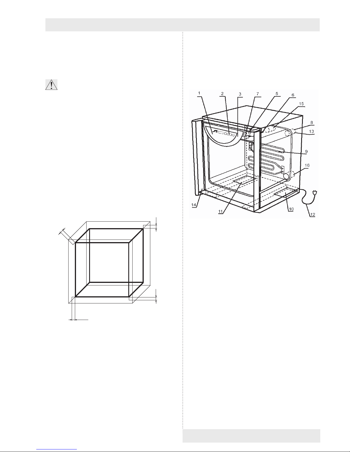
The oven shall be installed in a distance of
min. 100 mm from the rear and sidewalls.
The temperature of the outlet air on the
exhaust may be up to 250 °C (or 300 °C);
this area is labeled by .The walls near
the oven shall be incombustible.
The load-bearing capacity of the oor
during installation of the device shall
correspond to the weight of the unit itself
taking the weight of the maximum charge
into consideration (see chapter
5 - Parameters of the Unit).
The unit must not be placed on a support
that could cause a danger of re or
smothering in case of falling some hot
object out of the unit.
Noinammable,explosiveortoxic
materialsmaybeputintooven!The
same applies to materials that could
release such substances.
Material is only to be put on trays, never
directly on the bottom of the unit!
No articles may be put on he external
surface of the unit.
The unit is not intended for warming up the
liquids.
The units are not intended for use in the
atmosphere with a possible danger of
ammable or explosive anesthetics.
Any assembly or disassembly may be
done only when disconnected from the
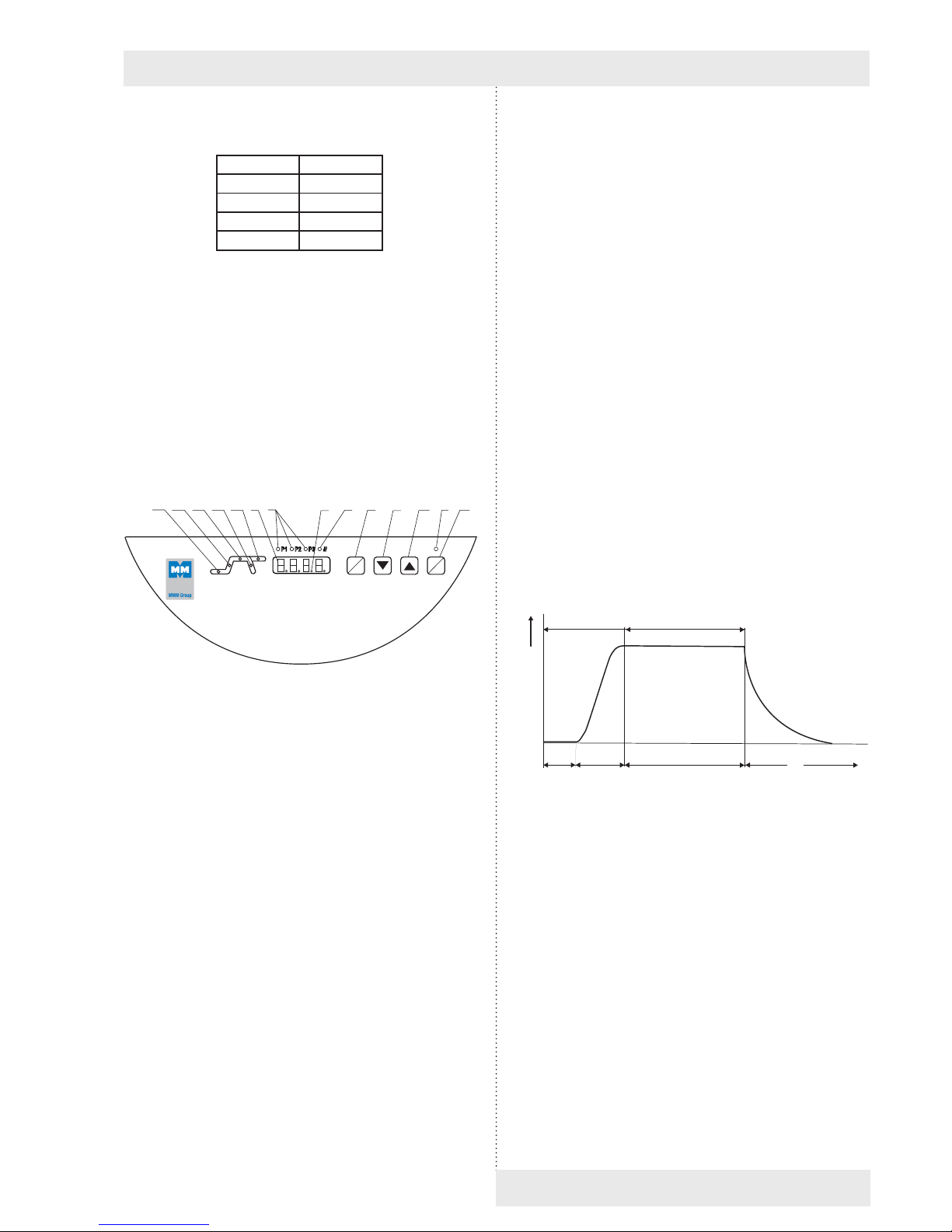
mains! After switching the unit off with
thekey(key11,g.4)theunitcomes
onlytoastand-bymode,however,itis
not disconnected from the mains!
● If the unit is not used for a longer time,
disconnect it from mains by pulling the
power cord out of the socket.
The units are supplied with the maximum
permitted temperature set to the maximum.
The power cord must not come in contact
with hot parts of the units – with the
exhaust hole cover.
● Protection of the temperature box, its
surroundings and processed material
against inadmissible temperature excess is
secured by a safety system.
Pull out and subsequently push in the
upper metal plate piece of internal chamber
carefully, there is a danger of cutting
through the rubber gasket of the chamber
through careless manipulation.
The maximum permitted loads: see chapter
5 - Parameters of the Unit.
When operating the cabinets at high
chamber temperatures there can be the
maximum allowed temperature of 70 °C at
their external surface (exhaust ports and
their surroundings and the surroundings
of the chamber sealing, window and door
surface in case of the optional type with
window in door) surpassed and there is a
danger of burns. Please be very careful.
● During the operation of the devices of
404 and 707 at high temperatures a
deformation of the inner door surface
occurs as a consequence of thermal
tension, which makes their closing more
Instructions for use
4 LSI-S_np_en_1309_mmm_V2.10_B2V

difcult. If you open the door in this state,
do not close them until the chamber
is cooled down. Otherwise the door
mechanism could be damaged.
Regularly – in daily intervals – check by
listening if after the start the fan of the case
is running.
2.3
USEFUL SPACE
The useful space is illustrated on Fig. No.1,
where X(D) = 10 % of the inner chamber depth,
X(W) = 10 % of the inner chamber width, X(H)1
is the distance from the lowest tray to the bottom
of the inner chamber, X(H)2is the distance from
the upper most tray to the ceiling of the inner
chamber. The required temperature accuracy
- see chapter 5 - Parameters of the Unit - is
achieved only within the space dened above
(in connection with DIN 12 880 - marked with
thick lines, thinner lines mark the inner chamber
walls). (It means, that over the last upper tray the
limits from chapter 5 - Parameters of the unit –
are not obligatory).
Fig. 1
3
description
of the unit
3.1
GENERAL VIEW
Fig. 2
1 - controller panel
2 - control keys
3 - plastic cover of the controller panel
5 - lever for air ap positioning
6 - case of PT 100 sensor
7 - fan (only for VC, ICV)
8 - exhaust with air ap (with all types)
9 - heating elements
10 - power board I
11 - power board II (only three-phase type)
12 - mains cord
14 - door sensor
15 - suction hole (only for VC, ICV, with air ap)
16 - suction hole (with types EC, DC, IC)
X
(H)
X (V)2
X (V)
1
X (Š)
Instructions for use
LSI-S_np_en_1309_mmm_V2.10_B2V 5

ECOCELL 22
VENTICELL 22
Instructions for use
Návod k použití LSI – linie Standard B2v strana 11
LSI_S_B2v_c_np1101 V 2.02_TT
VENTICELL 22 PŘEBÝVÁ POZICE 4
1234 5
678 9
6 LSI-S_np_en_1309_mmm_V2.10_B2V
VENTICELL 22
3.2
POWER CONNECTION AND
CONNECTORS
1 2
34
Fig. 5:
Foot of the unit with mains cord
- rear view (with the power board I)
1 - Interface for printer
2 - Mains supply
3 - Screws attaching the power board
4 - Power board panel (located in the foot)
9 Canon connector on the case
Pin Signal
2 RX
3 TX
5 GND
6 DSR
1234 5
678 9
Fig. 6: 9 Canon - Interface for protocol printer

25 Canon connector in the printer
Pin Signal
2 TXD
3 RXD
7 GND
20 DTR
The appliances, which are connected with the
connector RS-232C, must comply with valid
regulations in terms of electric safety and
electromagnetic compatibility.
Interface parameters: Baud 9600
Stopbit: 1
Parity: none
Databit: 8
3.3
CONTROL PANEL
Fig. 4
1 - display
2 -
decimal point - burns (the unit is
connected to the mains - stand-by mode)
3 -
the indicators of pre-selected programs:
- burn: program is active
- blink: program will be active in 5 sec.
5 - heating indicator light - burns:condition of
temperature regulator - heating active
6 - power indicator light - burns after
switching the unit on by ON/OFF swich
7 - Safety system indicator is ashing: The
temperature exceeded the chosen limit set
by the protective thermostat – the heating
is switched off (see more in Chapter 4.6
Safety System Functions and Setting)
8 - setting mode activation key
9 - setting the value downwards
10 - setting the value upwards
11 - switch (ON - switched on, OFF - stand by mode)
14 - Indicator light: blinks - set-up
mode, burns - the active part of the
program is time-delayed switching-on
Instructions for use
15 - indicator light: blinks - set-up mode,
burns - the active part of the program is
heating-up to present temperature
16 - indicator light: blinks - set-up
mode, burns - the active part of the
program is time-delayed switching-off
17 - Indicator light: blinks - set-up
mode, burns - decrease of temperature
after switching-off
18 - Indicator light: blinks - set-up mode,
burns - the active part of the program is
innite stay on the present temperature.
Indicator lights 14-18 blink - number of cycles
setting mode.
4
function and
operating
The unit can be set to various modes according
to the required function, i.e. the unit’s cycle can
be modied, as described below. In the gure a
complete course of one cycle with its stages is
shown.
t (x)
t
(°C)
0a b t (min)c
Segment Funktion
0 time-delayed switching-on,
a rise to the temperature,
b time-delayed switching-off
c temperature drop after switching off
The functions of the respective indicator lights
are described in chapter 3 - Description of the
Unit, and 3.3 - Control Panel.
4.1
STARTING AND SWITCHING-OFF
1. In case, that the unit was in the stand-by mode
before switching-off, a green dot in the right
lower part of the display will lit up, otherwise
the program, interrupted by switching off, will
continue.
x
w
ON
OFF
14 15 16 17 18 1 3 2 5 8 9 10 6 11
LSI-S_np_en_1309_mmm_V2.10_B2V 7

Instructions for use
8 LSI-S_np_en_1309_mmm_V2.10_B2V
2. Press the key ON/OFF. The indicator light
above the key, the indicator light of the pre-
selected program and the indicator light of the
initial active program stage will lit up.
If the temperature in the chamber will be lower
than the preset value, the heating indicator
light will burn as well - either permanently
or blinking (depending on heating controller
status - on or off).
3. Press the key ON/OFF. The display turns off,
only the green indicator light in the lower right
part is on (stand by). The total disconnection
from mains (in case of a long-term putting out
of operation or a maintenance) is achieved
by pulling the mains cord from a socket – see
also chapter Before installation.
4.2
SETTING-UP THE REQUIRED
VALUES OF TEMPERATURE,
TIME-DELAYED SWITCHING-OFF,
NUMbER OF CYCLES, TIME-
DELAYED PROGRAM START
1. Set the pre-selection of the program 1or 2 or
3 by pressing the key ▼ or ▲, after pressing
the key ▼ or ▲the indicator light of the next
program will start to blink. This program will
be activated in ca. 5 sec, if no other key is
pressed during this time. Setting by means
off ▼ or ▲, will cause the stop of the actually
running cycle and starting a new cycle with the
pre-selected parameters. The setting-up cycle
begins with setting the required temperature.
2 Press the key X/W, indicator lights 15, 16
(Fig.4) start to blink, by pressing the keys ▼▲
set the required temperature in °C on the display.
The lowest temperature interval, which can
be set and displayed with EC, DC, VC is 1 °C;
with IC, ICV it is 0,1 °C.
The indicator lights of the segments blink
permanently.
3. By pressing the key X/W change over to
the setting of time-delayed switching-off, by
pressing the keys ▼▲set the required value
in hours and minutes from 0 to 99 hrs and
59 min on the display, thereby the indicator
lights 16, 17 (Fig.4) blink. The symbol ---
corresponds to the timely unlimited exposure.
4. By pressing the key X/W change over to the
setting of number of cycles and by pressing
the keys▼▲ set the number of cycles from
1 up to 255 (more information on the cycles
see 4.3) - all indicator lights blink during the
setting up.
This function can be used only with the time-
delayed switching-off ≠ 0.
Select the option of cycles setting by using the
user menu.
5. By pressing the key X/W change over to the
stage of setting the time-delayed starting and
by pressing the keys ▼▲ set the required
value in minutes from 0 up to 99 hrs 59 min,
the indicator light 14 (Fig.4) blinks.
6. Start the program by double pressing the key
ON/OFF (the program start is announced by
an acoustic signal). Actual temperature with
time countdown will blink on the display during
the time-delayed program starting.
The heating is switched on after reaching the
time of zero and the display shows the actual
temperature in the chamber.
After reaching the required temperature:
a) in case of setting the time-delayed shut
down, the chamber temperature with the
preset time countdown starts to change on
the display or
b) in case of time unlimited switching-off, the
chamber temperature with the count up
time starts to change on the display. After
99 hours:59 min pass, time is displayed in
hours up to 999 hours. It is then displayed
by ∞ symbol (innity). When printing the
record on the printer, time is shown up to
999:59; the text “inni” is then printed.
Continuously lighting indicators inform about
the actual active phase of the programme.
The permanently lighting indicator lights
provide information on the actually active
program stage.
7. Individual values can be checked during the
program run - by pressing the key X/W the
required value is shown on the display, the
indicator lights blink, by the next pressing of
the key X/W within 5 seconds you will change
over to the next stage, in this way all settings
can be checked step by step.
The original program will continue, if no control
element within 5 seconds will be used.
8. In the similar way, you can change the already
set values during the programme operation, if
a) you will wait ca 5 second after setting of
new values, the programme continues with
changed values from the break point.
b) after setting the value you can start the
program by double pressing the key ON/OFF,
the program will start with new values from the
beginning.
Fan run and program end:
With all types containing fan the fan runs for
5 minutes after the program end and then it is
switched off.

Instructions for use
LSI-S_np_en_1309_mmm_V2.10_B2V 9
4.3
USER MENU
Enter the functions by pressing X/W + ▼
concurrently.
After you enter the functions, LEDs of all three
programmes switch on. Select the required
function U1, U2, … by means of the button ▼▲
and enter the function by X/W. After you enter:
a) U1 – printer’s printing period setting (Per.P)
from 1 to 255 min, or the print period switch-
off (“OFF”) by means of buttons ▼▲.
b) U2 – (CYcl) On or OFF – cycles permit or
prohibition are set by means of ▼▲ (for all
pre-sets at once); a cycle means a multiple
programme repetition with a pre-set delayed
switching off and on.
c) U3 - Prn or PC – data transfer via interface
RS 232 either onto the printer (Prn) or, in
case of using the program WarmComm, onto
the computer (PC); set the sign Prn or PC by
means of ▼▲.
d) U4 – setting of the fan speed (VEnt). The
speed could be changed in steps: 50, 60, 70,
80, 90 and 100 %. The initial setting is 100 %.
The speed is regulated with the accuracy of ±
5 %.
e) U5 - enabling (ON) or disabling (OFF) of the
acoustic signalizing at the exposure end (after
the end of the last cycle in case of cycling).
Within the original adjustment the acoustic
signalling is permitted.
f) U6 - Safety system functioning as a protective
thermostat
User safety upper temperature limit – setting
of the maximum user-permitted exposure
temperature (SFt.H). Change this value
by means of ▼▲ and conrm by ON/OFF
pressing. When setting this maximum value,
the real temperature course, namely its
potential overshoot during temperature rising,
must be taken into account. If the pre-set
maximum permitted temperature is lower
than the required exposure temperature,
the display shows the warning “SEt tEMP
CroSSEd SAFEtY USEr LiMit” , because the
safety system would otherwise be activated
during the cycle. The resolution and range
of the setting correspond to the resolution
and range of the required temperature. The
highest temperature has been pre-set as
default.
g) U8 – Safety system – setting of the maximum
onset phase duration (SPt.f). After ▼▲
pressing, the actual maximum onset phase
duration is displayed. It can then be changed
by 1-hour steps within the range from 1 to 24
hours, or the time watching can be switched
off, which is then displayed in form of “OFF“.
Conrm by ON/OFF pressing. Default setting:
Time watching is switched off.
h) U9 – Selection of exible sensor displaying.
(Yes/No).
i) U14 – Alarm – setting of the permitted
lower deviation from the required exposure
temperature (dlt.L). Set the deviation by
means of in the range from -0.1 to -99.9 °C,
or the function can be switched off, which is
displayed as “OFF”. The alarm function has
been switched off as a default.
j) U15 – Alarm – setting of the permitted
upper deviation from the required exposure
temperature (dlt.H). Set the deviation by
means of in the range from +0.1 to 99.9 °C,
or the function can be switched off, which is
displayed as “OFF”. The alarm function has
been switched off as a default.
Exit any user function setting by X/W pressing.
Exit any user function selection by ON/OFF
pressing.
4.4
ALARM FUNCTION
The alarm function can be used for the real
chamber temperature watching. Set the
maximum (upper) and minimum (lower) permitted
deviations in user settings U14 and U15. The
said values are then watched by the control
unit. If the actual temperature drops below the
lower value during the exposure phase, the
appropriate message “Lo ALArm” is displayed
till its cancellation by X/W button. If the actual
temperature exceeds the upper limit during the
temperature rise, exposure and cooling, the
appropriate message “Hi ALArm” is displayed till
its cancellation by X/W button. The alarm switch-
on or cancellation is recorded to the printer or
the PC programme. The alarm performs no other
than informing activity.
ATTENTION! The alarm has an information
function only. It will neither remove nor restrict
the cause of the alarm. To restrict the heating in
case of a defect, use the safety system and its
setting in U6.
4.5
PROTOCOL PRINTING
DPT 6333 printer is recommended for the record
printing on the printer. Other printers may also be
used, e.g. CITIZEN, model iDP 3110-24 RF-A.
Printing to a PC application (Printer Archiv) is
allowed as well.Archiv.

Instructions for use
10 LSI-S_np_en_1309_mmm_V2.10_B2V
4.5.1
INSTALLATION AND SETTING OF
THE PRINTER
DPT-6333-V24 does not require any microswitch
setting by the user.
Setting the DIP microswitches of the printer
CITIZEN iDP 3110:
all four pins are in the lower position OFF.
Setting the DIP microswitches of the printer
CITIZEN CBM 910:
OFF / ON / OFF / ON / OFF / ON / ON / OFF
(from the left to the right).
CBM 910II: OFF / ON / OFF / OFF / OFF / OFF
/ ON / OFF.
After the setting is changed, the printer must be
switched off and on either by the switch or by
disconnection from the power supply.
(A different type of the printer must be adjusted
with the help of the printer´s manual and the data
on the interface RS232 shown on the case.)
Connect the printer to the device by means of a
cable with serial connector (RS-232C). Connect
one end of the cable to the printer socket (see
Fig. 4) and the other one to the connector in the
rear part of the printer. Connect the printer to the
electric power mains by means of an adapter.
Some types require the switch on the right side
of the printer to be switched on. The indicators
POWER and SEL light up. The printer is in the
on-line mode. Paper is fed by pressing the LF
button (in the on-line mode only, i.e. after the SEL
button pressing – the SEL indicator turns off. To
renew the on-line mode, the SEL button must
be pressed – the SEL indicator lights up). The
printer can print in the on-line mode only!
Follow the chapter User Support Functions to set
the type of data from the COM output connector
(user mode U3) and the required print interval
(user mode U1).
By the printer interval setting you can determine
the time intervals of actual chamber temperature
printing. The interval is shown in the record
heading.
The printer interval can be set on the display
in the range from tmin = 1 min to tmax = 255 min
(i.e. 4 hours 15 min) in 1-minute increments.
4.5.2
PRINTING
1. The printer prints out the heading showing the
device type, programme number, number of
cycles, pre-set temperature, time of the start
delay, and the required time interval.
2. Then the printer prints out the procedural
data and titles of the procedural data columns
(physical unit inclusive).
3. Below that, the values of the following
procedural data are printed out:
- Actual temperature in the chamber;
- Time from the programme start.
4. Other printed data:
- Start of individual phases;
- Change of any required value;
- Change of a user function inuencing the
cycle procedure (U1, U3, U4, U6, U8) m,
including the new value printing;
- Alarms activation/deactivation, including the
description;
- For IC,ICV: Activation or deactivation of
the safety system warning, including the
description;
- Error state activation, including the
description.
5. In case of power failure and subsequent
power recovery, the printer prints out “-->
Power recovery!” Counting of the printing time
intervals starts from the moment of power
recovery. A new heading is printed out after
switching the device off and on by means of
ON/OFF.
If there is a power failure of the printer only, or
if the printer is switched off, the printer shows
no message after the power recovery or the
printer switch-on.
4.6
SAFETY SYSTEM FUNCTION AND
SETTING
The safety system watches the exposure process
controlled by the control circuit. It also performs
the function of a safety thermostat and serves to
protect the temperature box, its surroundings and
the processed material against an inadmissible
excess of the set temperature (it will e.g. prevent
the damaging or destruction of material samples
in case of the temperature regulator damage, or
unintended setting of a higher temperature than
that tolerated by the sample in the unit chamber).
Supervision is performed both under the normal
operation and in a Stand By.
The safety system measures the temperature
independently at the same place like the
regulatory sensor and counts the time

Instructions for use
LSI-S_np_en_1309_mmm_V2.10_B2V 11
independently. If the set maximum temperature
and period of time are exceeded, the safety
relay switches off the heating, indicates the error
state by its indicator ashing (red) and passes
the information about the error to the controlling
unit which then passes to the error regimen and
indicates the error.
To cancel the error by the user, hold X/W. The
controlling unit cancels the error state in the
safety system circuit. The device passes to a
break state in which parameters can be reset, or
you can let the chamber cool. The device is put
into operation by pressing ON/OFF.
4.6.1
CHANGE OF MAxIMUM AND
MINIMUM VALUES
It is performed in the user settings U6, U8 – see
the safety system function diagram and
description of the user settings. Minimum
difference from the set regulated temperature
should be ± 5 °C.
4.6.2
SUPERVISORY CIRCUIT DIAGRAM
FUNCTION
T limiting – threshold temperature is the
maximum operation temperature permitted by the
manufacturer in all phases and watched by the
safety system. Its value depends on the device
type and cannot be changed.
T User High – safety user upper temperature
limit is the maximum temperature permitted by
the manufacturer for the phase of temperature
rise, exposure and cooling, pre-set in U6 and
watched by the safety system.
T delay – maximum allowable temperature of
the delayed switching phase. It is set itself at
the cycle beginning to the sum of the actual
temperature plus 30 °C.
Tnal- maximum permitted temperature after
termination of cooling. It reaches the T exp max
temperature or 55 °C, whichever is lower.
D delay - time of the delayed switching may vary
from the set time for ± 2 min.
D rise - max. rise time according (Safety Time) to
the setting in the user mode U8.
D exposition - exposition time may vary from the
set time for +3 min / - 0 min.
D cooling - max. cooling time is set to 24 hours.
4.6.3
TEMPERATURE LIMITS OF THE
UNITS
ECOCELL 280 °C
DUROCELL 150 °C
VENTICELL 280 °C
VENTICELL 300 °C 330 °C
INCUCELL 100 °C
INCUCELL 100 °C 130 °C
4.6.4
CHECKING THE SAFETY RELAY
FUNCTION
The test is performed automatically in the
phase of the temperature rise, without the cycle
inuencing, and after the period between tests
elapsing (3,000 hours). The said time is counted
in the exposure phase. After the device is
connected to the power mains, the safety relay
state is monitored as well. If the test result is not
good, Err 24 is announced.
4.6.5
CHECKING THE CORRECT ACTIVITY
OF THE SAFETY SYSTEM
Checking is performed after the required
temperature reached the steady state
(10 minutes at least) in the exposure phase. If
you change the user safety temperature in U6,
do not forget to record each temperature change
in the safety system by ON/OFF pressing before
leaving the user mode.
Temperature exceeding:
•Activate the user service, mode U6.
•Set the user safety upper temperature to a
value exceeding the required one by 5 °C. The
protective circuit must not react.
•Set the user safety upper temperature to
a value 5 °C below the required one. The
protective circuit must react. The safety
system indicator lights up and error Er13 is
announced. In INCUCELL, the safety system
indicator lights up only.
Návod k použití LSI – linie Standard B2v strana 20
V 1.15_TT LSI_S_c_np0800
4.6.2 Diagram funkce kontrolního obvodu
T mezní - max. dovolená teplota ve všech fázích, její hodnota závisí na typu přístroje.
T exp max - max. dovolená teplota fáze náběhu, expozice, i chladnutí dle nastavení v uživatelském módu.
T exp min - minimální dovolená teplota fáze expozice dle nastavení v uživatelském módu.
T zpož - max. dovolená teplota fáze zpožděného zapnutí. Nastaví se sama na dle skutečné teploty +10°C.
T konečná - max. dovolená teplota po skončení chladnutí. Je stejná s T zpož.
D zpož - doba zpožděného zapnutí se může lišit od nastavené o +/- 2 min.
D náběhu - max. doba náběhu dle nastavení v uživatelském módu.
D expozice - doba expozice se může lišit od nastavené o +3 min / -0 min.
D chladnutí - max. doba chladnutí je nastavena na 24 hodin.
4.6.3 Odečítání času mezi testy bezpečnostního relé
Počítadlo se snižuje při započetí každé nové hodiny expozice. Jeho stav je zobrazen
v uživatelském módu U12. Při dosažení stavu 0 je vyžadován před expozicí test
bezpečnostního relé, jinak není expozice umožněna. Dobrý výsledek testu toto počítadlo
znovu nastaví na výchozí stav. (3000h).
4.6.4 Test bezpečnostního relé
Test probíhá autonomněve fázi náběhu, po vypršení času mezi testy. Pokud test probíhá,
vypisuje se na displeji kromě skutečné teploty regulačního a případněflexibilního čidla i
nápis „SAFETY TEST“.
Pokud se zobrazuje „SAFETY TEST – SET TEMPERATURE UP“ ve skříni je ještě vysoká
teplota – nutno nechat vychladit. Tyto nápisy se zobrazují i ve fázi zpožděného zapnutí.
Test je ale také možné si vyžádat v uživatelském módu U12. Pokud test proběhl dobře,
následuje dále fáze expozice, dle nastavených parametrů. Pokud test neproběhl dobře, je
vyhlášena chyba Err 24.
T mezní
T žádaná
T exp max
T exp min
Teplota
Čas
T zpož T konečná
D zpož D náběhu D expozice D chladnutí
T skutečná
Naformátováno: Odrážky a
číslování
T limit
T exp max
T exp min
T nal
D cooling
T delay
Time
D rise
Temperature
D exposition
D delay
T desired
T actual
T User High

Instructions for use
ON
OFF
X
W
START
STOP
RH 5 6
Program Segment °C
*
1 2 3 4 5 6 7
8910 11 12 13
12 LSI-S_np_en_1309_mmm_V2.10_B2V
CAUTION:
The safety system function differs according to
the device type.
VENTICELL, ECOCELL and DUROCELL
devices
If the maximum set permitted temperature in
the chamber is exceeded, the safety system
will switch off the heating elements and the
safety system indicator lights up (the device
does not heat although the heating indicator is
lighting). Even if the temperature in the chamber
drops below the set limit, the heating remains
disconnected. To restart it, the button X/W must
be held pressed. The device passes to the break
state in which the parameters can be set or you
can let the chamber cool. The device will be
switched on by pressing ON/OFF.
Any event of temperature exceeding and
error announcement is printed on a printer if
connected.
DevicesINCUCELLandINCUCELLwitha
ventilator
If the maximum set permitted temperature in
the chamber is exceeded, the safety system will
switch off the heating elements and the safety
system indicator lights up (the device does not
heat although the heating indicator is lighting).
After the temperature in the chamber drops
below the set limit, the heating is automatically
switched on again. The safety system indicator
will turn OFF. Any event of temperature
exceeding and return is printed on a printer if
connected.
4.7
LIST OF ERROR MESSAGES
When an error is displayed, you can switch to a
textual description of the error, and/or other data
displaying related to the error and recorded in
the moment of the error occurrence. Use ▼▲ for
switching. Leave this display by X/W pressing.
Er 11 – Wrong temperature sensor of the
safety system
Contact the service centre.
Er13 – The temperature exceeds the user
upper limit watched by the safety system.
Check the limit setting in the user mode U6:
The limit may not be lower than the required
temperature, taking also account of overshoot or
uctuation.
After you change the value, check by a repeated
entry in the U6 mode whether the pre-set value
has been saved. If not, check the correct setting
procedure in the instructions for use.
Check also whether the device has not been
overheated without the device fault, e.g. by the
load ignition.
Er15–Thedevicethresholdtemperature
watched by the safety system has been
exceeded.
Check whether the device has not been
overheated without the device fault, e.g. by the
load ignition.
Er17 – The maximum phase time was
exceeded
If there is any error during the temperature rise,
compare the rise duration with the setting in the
user mode 8 and/or assess the reasons for the
long rise duration, or increase the maximum
controlled period in mode U8.
Er23 – the temperature measured by the
control system differs from the temperature
measured by the safety system.
Check whether the error was not caused by
strong temperature changes, e.g. by the door
opening and air blowing.
Er24 - The safety relay did not pass the test
Contact the service centre.
Er 30 to Er 49 – Door blocking errors
See more in the chapter Two-Door Pass-through
Model with Automatic Door Blocking
Er 50 and Er 51 – Wrong regulatory sensor
Contact the service centre.
Er52andEr53–Errorsofexiblesensors
Check the integrity of the exible sensor.
SEt tEMP CroSSEd SAFEtY USEr LIMIt.
Warning message informing only that the pre-
set temperature is either lower or higher, but
too close (up to 3 °C) to the user safety upper
temperature checked by the safety system (U6),
which probably will cause the safety system
activation. Cancel the message by X/W pressing
and change one of the two given values.
Hi ALARM
Lo ALARM
Alarm activation announcement. See the chapter
ALARM FUNCTION

Instructions for use
Other error messages
Disconnect the device from the power supply and
then reconnect it.
If the error repeats, contact the service centre.
4.7.1
NOT DISPLAYED ERRORS
Red indicator with the safety thermostat
symbol is lighting and the sound alarm is
activated(intermittenttone).Thesafety
system found that the set temperature had
been exceeded. The error is not indicated;
information on the display is normal.
AppliesonlytoINCUCELLdevices.
Check the setting between U6.
Red indicator with the safety thermostat
symbol is lighting; the control unit does not
react. The safety system switched off the safety.
Disconnect the device from the power supply and
reconnect relay; the heating elements have no
current supply. Disconnect the device from the
power supply and reconnect it.
Thedevicedoesnotshowanyinformation
(the display is not lighting).
Check whether the device is connected to the
electric power mains. If yes, try to disconnect and
reconnect it.
Thedevicedoesnotreacttoanybutton.
Disconnect the device from the power supply and
reconnect it.
The printer does not print, or prints some
nonsense.
Check whether the device is switched to data
sending to the printer (U3); check the print period
(U1). Check whether the printer is connected to
power supply and switched to the data transfer
rate 9600 Bd.
Therequiredtemperatureisovershotalot
repeatedly during the exposure cycle and is
reached only after some time.
Check whether the door and the device ap are
closed properly.
The required temperature is exceeded a lot
duringtheexposurecycle;thedevicestays
overheated.
Switch the device off.
The required temperature is reached during
the exposure cycle only after a too long time.
Check whether the door and the device ap
are closed properly. Check whether the mains
voltage reaches the values required by the
Instructions for Use, chapter Mains Connection.
Thetemperatureneverreachestherequired
valueduringtheexposurecycle.
Check whether the mains voltage reaches the
values required by the Instructions for Use,
chapter Mains Connection.
4.8
ADjUSTING AND FUNCTION
OF THE AIR FLAP
Function description:
The air ap is intended for ventilating the
chamber space of the unit, for example when
drying wet materials.
Airapadjustment:
Adjust the air ap when installing the unit. Put the
control lever of the air ap to the closed position
and adjust the air ap in the exhaust hole at the
rear wall of the unit so that it closes the entire
ventilating hole. Hold the shaft of the ap with
pliers to prevent turning over.
Note:
With VENTICELL and INCUCELL WITH FAN it
is necessary, in addition to the exhaust ap, to
adjust the sucking air ap as well.
Theairapcontrol:
If you put wet materials into the unit to dry it
before tempering, put the air ap in the position
open so that the humidity could freely leave the
chamber. After nishing the drying put the air ap
in the position closed.
Note:
Operating the unit with an open air-ap increases
the power consumption and the maximum
temperatures may not be reached.
LSI-S_np_en_1309_mmm_V2.10_B2V 13
CLOSED OPE
N
DOORS

4.9
ExCHANGING THE DOOR
SEALING AND ADjUSTING THE
DOOR
Remove the sealing completely, start in the middle
lower part.
Fix the new sealing on the edge of the chamber,
start in the middle lower part. Squeeze the
sealing between the chamber and the outer
cover.
The door is adjustable at four points:
– in the left upper part by means of bolts and
nuts – sketch position 3
– in the left lower part by means of bolts and
nuts – sketch position 4
– in the right upper part by means of internal
hexagon screw – sketch position 2
– in the right lower part after loosening the
screw with internal hexagon adjusting in front-
back direction of the door hinge is possible –
sketch position 1.
In the apparatus of the volume of 22 there is
only one adjustable screw in the side of the door
locking device.
Adjust the door so that when closed the rubber
sealing of the chamber would t to the sheet of
the oating door along the whole perimeter. To
check it up place a sheet of paper between the
sealing and the metal sheet of the oating door
before it is closed, it is possible to take the paper
out against a small resistance.
Instructions for use
1
2
3
4
14 LSI-S_np_en_1309_mmm_V2.10_B2V
Návod k použití LSI – linie Standard B2v strana 26
V 2.02_TT LSI_S_c_np0800
VENTICELL 22
VENTICELL 22

LSI-S_np_en_1309_mmm_V2.10_B2V 15
Instructions for use

ECOCELL (EC), DUROCELL (DC), VENTICELL (VC), INCUCELL/INCUCELL V (IC/ICV)
Technical data
Interior of stainless steel
material DIN No 1.4301
volume EC, VC, IC / ICV
DC
cca liters 22
22
55
55
111
111
222
222
222/2+ 404
-
404/2+ 707
-707/2+
-
width mm 240 400 540 540
540 540 540 940 940
depth EC, DC, VC
IC / ICV
mm 320 390
370
390
370
540
520
540 540
520
540 540
520
540
-
height mm 295 350 530 760
760 1410 1410 1410 1410
Tray bearing plate, width x depth
racks
distance of the wiring
standard equipment
mm
No
mm
pcs. included
185x265
4
60
2
380x335
4
70
2
520x335
7
70
2
520x485
10
70
2
520x485
10
70
2
520x485
19
70
2
520x485
19
70
2
920x485
19
70
2
920x485
19
70
2
Maximal load screens
steel sheet racks
in total
kg/screen
kg/rack
kg/case
10
10
25
20
20
50
20
20
50
30
30
70
30
30
70
30
30
100
30
30
100
50
20
130
50
20
130
Door psc. 1 1 1 1
2 1 2 2 4
External dimensions
(including door and handle)
width
depth
height (incl.Feet F and Rolls R)
Ø of the air branch outer / inner
mm
mm
mm
mm
406
580
604F
52/49
620
640
680F
52/49
760
640
860F
52/49
760
790
1090F
52/49
760
790
1110F
52/49
760
790
1910R
52/49
760
790
1910R
52/49
1160
790
1910R
52/49
1160
790
1910R
52/49
Package dimensions (three
layers carton)
width
depth
height (incl. palette)
mm
mm
mm
465
665
655
700
730
880
830
730
1050
830
860
1280
830
860
1280
830
860
2070
830
860
2070
1230
860
2080
1230
860
2080
Weight nett
brutt
kg
kg
31
36
55
66
75
87
100
116
105
121
150
175
150
185
215
240
230
255
Elektricity power W input [stand by] 5 5 5 5
5 5 5 5 5
- mains 50/60 Hz max. power input kW VC
DC
IC / ICV
EC
0,96
0,92
0,24/0,96
0,92
1,3
1,2
0,3 / 0,7
1,2
1,9
1,8
0,3 / 0,7
1,8
1,9
1,8
0,5 / 0,7
1,8
3,7 3,7
-
0,9 / 1,3
3,6
5,5 4,9
-
0,9 / 1,3
5,4
7,2
voltage V ****) EC, DC, VC
IC / ICV
230
230 230
230
230
230
230
230
400/3NPE 400/3NPE
230
400/3NPE 400/3NPE
230
400/3NPE
-
current A VC
DC
IC/ICV
EC
4,2
4,0
1,1 / 4,2
4,0
5,6
5,2
1,3 / 3
5,2
8,3
8,3
1,3 / 3
7,8
8,3
7,8
2 / 3
7,8
5,2
5,2
-
3,9 / 5,6
7,8
7,9
7,8
-
3,9 / 5,6
7,8
10,4
voltage V ****) EC, DC, VC
IC / ICV
115
115
115
115
115
115
115
115
115/3PE 115/3PE
115
115/3PE 115/3PE
230
115/3PE
-
Temperature data
Working temperature
(beginning of the regulation)
od 10 °C above ambient temp. to °C
od 5/10 °C
above ambient temp. to °C
od 5 °C above ambient temp. to °C
VC **)
IC / ICV ***)
EC
DC
250 /300
70 / 100
250
125
250 / 300
70 / 100
250
125
250 / 300
70 / 100
250
125
250 / 300
70 / 100
250
125
250 / 300 250 / 300
70 / 100
250
-
250 / 300 250 / 300
70 / 100
250
-
250 / 300
-
-
-
The temperature
deviations*****) according to
DIN 12 880, Section 2, from the
average value of the working
temperature in the space of the
chamber, when the ventilation
ap and doors are closed
VC (>50 °C) space deviation
time deviation
cca (±) % Average value
In the space of the
chamber cca (±) ºC
1,1
0,3
1
0,4
1
0,4
1
0,4
1
0,4
1,8
0,9
1,5
0,4
2,5
0,4
2,5
0,74
IC/ICV
at 37 °C
space deviation
time deviation
cca (±) °C
do (±) °C
1,1/0,4
0,4/0,1
<0,5/≤0,3
≤0,2
<0,5/≤0,3
≤0,2
<1/≤0,3
≤0,2
<1/≤0,8
≤0,2
<1,5/≤1,5
≤0,2
-
-
EC space deviation
time deviation
cca (±) % Average value
In the space of the
chamber cca (±) ºC
2,7
1,0
2
≤0,3
2
≤0,8
2
≤0,8
2,5
≤1
3,5
≤1
-
-
DC
at 100°C
space deviation
time deviation
cca (±) % Average value
In the space of the
chamber cca (±) ºC
3,1
0,4
2
≤0,3
2
≤0,8
2
≤0,8
-
-
-
-
-
-
Temperature
rise time with
closed air ap
and at the voltage
of 230 V ± OV
250 °C VC
EC cca min. 28
54
49
59
53
60
70
99
33 58
85
43 64
95
50
-
100 °C DC 34 41 48 50
- - -
37 °C IC/ICV 70/8 49 / 41 57 / 51 79 / 66
41 / 38 59 / 51 -
Heat emision at 250 °C EC, VC cca W 300 / 420 590 760 990
1300 1940 2400 2550 3300
100 °C DC 140 380 490 630
- - -
37°C IC/ICV 20/70 30 45 45
65 85 -
Air exchange
rate at
150 °C VC
EC
cca/h 45
6
45
8
49
12
24
5
24 18
4
18 12
3
12
-
100 °C DC 6 8 12 5
- - -
37 °C IC/ICV 4 / 45 5 / 45 5 / 49 5 / 24
5 / 18 5 / 12 -
5 parameters of the unit
Note: All technical data are related to 22 °C ambient temperature and ± 10 % voltage swing (if not specied otherwise).
For other parameters see section 5.1 – Electric connections
*) Approx. 50 % of the tray area can be lled in a way a uniform air circulation is enabled inside the chamber.
**) Standard type is up to 250 °C, optional type is up to 300 °C ***) Standard type is up to 70 °C, optional type is up to 99,9 °C
****) Supply voltage is indicated on the type lable of the unit *****) Temperature deviations were measured in accordance with DIN 12 880
+) Two-door open-through model, in Venticell only
16 LSI-S_np_en_1309_mmm_V2.10_B2V

ECOCELL (EC), DUROCELL (DC), VENTICELL (VC), INCUCELL/INCUCELL V (IC/ICV)
Technical data
Interior of stainless steel
material DIN No 1.4301
volume EC, VC, IC / ICV
DC
cca liters 22
22
55
55
111
111
222
222
222/2+ 404
-
404/2+ 707
-707/2+
-
width mm 240 400 540 540
540 540 540 940 940
depth EC, DC, VC
IC / ICV
mm 320 390
370
390
370
540
520
540 540
520
540 540
520
540
-
height mm 295 350 530 760
760 1410 1410 1410 1410
Tray bearing plate, width x depth
racks
distance of the wiring
standard equipment
mm
No
mm
pcs. included
185x265
4
60
2
380x335
4
70
2
520x335
7
70
2
520x485
10
70
2
520x485
10
70
2
520x485
19
70
2
520x485
19
70
2
920x485
19
70
2
920x485
19
70
2
Maximal load screens
steel sheet racks
in total
kg/screen
kg/rack
kg/case
10
10
25
20
20
50
20
20
50
30
30
70
30
30
70
30
30
100
30
30
100
50
20
130
50
20
130
Door psc. 1 1 1 1
2 1 2 2 4
External dimensions
(including door and handle)
width
depth
height (incl.Feet F and Rolls R)
Ø of the air branch outer / inner
mm
mm
mm
mm
406
580
604F
52/49
620
640
680F
52/49
760
640
860F
52/49
760
790
1090F
52/49
760
790
1110F
52/49
760
790
1910R
52/49
760
790
1910R
52/49
1160
790
1910R
52/49
1160
790
1910R
52/49
Package dimensions (three
layers carton)
width
depth
height (incl. palette)
mm
mm
mm
465
665
655
700
730
880
830
730
1050
830
860
1280
830
860
1280
830
860
2070
830
860
2070
1230
860
2080
1230
860
2080
Weight nett
brutt
kg
kg
31
36
55
66
75
87
100
116
105
121
150
175
150
185
215
240
230
255
Elektricity power W input [stand by] 5 5 5 5
5 5 5 5 5
- mains 50/60 Hz max. power input kW VC
DC
IC / ICV
EC
0,96
0,92
0,24/0,96
0,92
1,3
1,2
0,3 / 0,7
1,2
1,9
1,8
0,3 / 0,7
1,8
1,9
1,8
0,5 / 0,7
1,8
3,7 3,7
-
0,9 / 1,3
3,6
5,5 4,9
-
0,9 / 1,3
5,4
7,2
voltage V ****) EC, DC, VC
IC / ICV
230
230 230
230
230
230
230
230
400/3NPE 400/3NPE
230
400/3NPE 400/3NPE
230
400/3NPE
-
current A VC
DC
IC/ICV
EC
4,2
4,0
1,1 / 4,2
4,0
5,6
5,2
1,3 / 3
5,2
8,3
8,3
1,3 / 3
7,8
8,3
7,8
2 / 3
7,8
5,2
5,2
-
3,9 / 5,6
7,8
7,9
7,8
-
3,9 / 5,6
7,8
10,4
voltage V ****) EC, DC, VC
IC / ICV
115
115
115
115
115
115
115
115
115/3PE 115/3PE
115
115/3PE 115/3PE
230
115/3PE
-
Temperature data
Working temperature
(beginning of the regulation)
od 10 °C above ambient temp. to °C
od 5/10 °C
above ambient temp. to °C
od 5 °C above ambient temp. to °C
VC **)
IC / ICV ***)
EC
DC
250 /300
70 / 100
250
125
250 / 300
70 / 100
250
125
250 / 300
70 / 100
250
125
250 / 300
70 / 100
250
125
250 / 300 250 / 300
70 / 100
250
-
250 / 300 250 / 300
70 / 100
250
-
250 / 300
-
-
-
The temperature
deviations*****) according to
DIN 12 880, Section 2, from the
average value of the working
temperature in the space of the
chamber, when the ventilation
ap and doors are closed
VC (>50 °C) space deviation
time deviation
cca (±) % Average value
In the space of the
chamber cca (±) ºC
1,1
0,3
1
0,4
1
0,4
1
0,4
1
0,4
1,8
0,9
1,5
0,4
2,5
0,4
2,5
0,74
IC/ICV
at 37 °C
space deviation
time deviation
cca (±) °C
do (±) °C
1,1/0,4
0,4/0,1
<0,5/≤0,3
≤0,2
<0,5/≤0,3
≤0,2
<1/≤0,3
≤0,2
<1/≤0,8
≤0,2
<1,5/≤1,5
≤0,2
-
-
EC space deviation
time deviation
cca (±) % Average value
In the space of the
chamber cca (±) ºC
2,7
1,0
2
≤0,3
2
≤0,8
2
≤0,8
2,5
≤1
3,5
≤1
-
-
DC
at 100°C
space deviation
time deviation
cca (±) % Average value
In the space of the
chamber cca (±) ºC
3,1
0,4
2
≤0,3
2
≤0,8
2
≤0,8
-
-
-
-
-
-
Temperature
rise time with
closed air ap
and at the voltage
of 230 V ± OV
250 °C VC
EC cca min. 28
54
49
59
53
60
70
99
33 58
85
43 64
95
50
-
100 °C DC 34 41 48 50
- - -
37 °C IC/ICV 70/8 49 / 41 57 / 51 79 / 66
41 / 38 59 / 51 -
Heat emision at 250 °C EC, VC cca W 300 / 420 590 760 990
1300 1940 2400 2550 3300
100 °C DC 140 380 490 630
- - -
37°C IC/ICV 20/70 30 45 45
65 85 -
Air exchange
rate at
150 °C VC
EC
cca/h 45
6
45
8
49
12
24
5
24 18
4
18 12
3
12
-
100 °C DC 6 8 12 5
- - -
37 °C IC/ICV 4 / 45 5 / 45 5 / 49 5 / 24
5 / 18 5 / 12 -
5.1
ELECTRIC CONNECTIONS
Basic data for connection:
Mains
connection:
230V/50(60)Hz
400V/50(60)Hz, 3NPE;
115V/50(60)Hz;
115V/50(60)Hz, 3PE
(standard types are marked with bold face)
Mains voltage uctuation ±10 %
Protection against
dangerous contact - class:
I
External circuits insulation
double insulation
The mains supply for the three-phase units must be
ensured by a switch or circuit breaker which serves
for disconnection. Such a switch or circuit breaker
must be:
– A component part of the building installation;
– Placed in an immediate vicinity of the unit and
accessible easily by the operator;
– Labelled as the device disconnecting element;
– Rated correctly and must comply with the
requirements of the standards IEC 60947-1 and
IEC 60947-3.
Protection
according to
EN 60529
IP 20
Overvoltagecategoryaccordingto
(IEC 664 – EN 61010)
II in case of pollution degree 2
Used fuses:according to corresponding
diagrams in the Service
instructions
Ambient conditions:
– ambient temperature: +5 °C to +40 °C
– max.relative humidity: 80% at the temperature up
to 31 °C
– maximal altitude: 3000 m
6
cleaning and
decontamination
of the unit
Clean the unit while cold and when the power
supply cord is disconnected from the mains.
Clean the interior walls of the chamber as well as
the exterior of the unit with water and detergent,
or possibly with suitable chemicals. Abrasive
cleaning agents may scratch the metal sheets.
If you want to clean the outer jacket of the
chamber, take the inner walls of the chamber out
as follows:
Shift the upper wall of the chamber out of the
unit, take out the sidewalls, the bottom and
the rear wall. Put the unit together in a reverse
Instructions for use
LSI-S_np_en_1309_mmm_V2.10_B2V 17

Instructions for use
sequence after it has been cleaned, be careful
and slide in the bottom and the sidewalls as far
as behind the four projections in the front part of
the chamber.
In case some contaminated material has
escaped into the chamber the user is responsible
for proper decontamination of all contaminated
surfaces with suitable and approved disinfecting
agent.
Casesofvolume22–EC,DC,IC:
Unbolt the screws in the back part of the ceiling
and of the bottom of the chamber. By pulling out
the walls in the direction to the door you release
the walls and remove them from the apparatus.
When you perform the assembly, you insert
the front bend of the bottom under the holder
of the heating radiator and lock the bottom with
a screw. When you perform the assembly of
the ceiling you put the back part on the sensor
holder, put the front bend of the ceiling on the
ceiling holder and lock with a screw.
(When you perform the assembly/disassembly
of VC, ICV, use the identical procedure, after
releasing the screw of the bottom, you tilt out the
back wall.)
Before using some other cleaning or
decontamination method different from our
recommendation, it is suitable for the user to
be informed by with the producer whether the
intended method cannot cause damage to the
device.
7
maintenance
No special maintenance is necessary. In case of
any troubles, please, call the service.
Inspection of electric components:
The cases of thermal technique are destined for
a basic/normal environment, the manufacturer
recommends the inspection period of 1 year, if
not determined by local regulations otherwise.
Inspection operations:
Inspection of the electrical installation, particularly
of the electric power supply, of connecting
terminals and a protective terminal.
Check the integrity of the conductor insulation
(for example, due to wearing through, burning
etc.) and the rm connection in the terminals.
The resistance of the protective connection is
< 0.1 Ohm, the resistance of the supply is not
included.
18 LSI-S_np_en_1309_mmm_V2.10_B2V
If the case is placed in a different environment,
the inspection must be performed in accordance
with the local standards.
The service inspection is the matter of agreement
between the client and the service organization.
8
warranty and
service
The guarantee period is marked on the certicate
of warranty.
The warranty refers to manufacturing defects or
material defects on condition that:
•the product has been installed and used in
accordance with the Instructions for use
• the cause of the defect was not a insufcient
maintenance, unqualied intervention in the
device or damage through external impacts.
The warranty does not relate to natural wear of
material and to consumer material, such as e.g.
door sealing, materials for recording devices,
accumulators etc. If a defect occurs, draw claims
to a warranty repair directly at the nearest MMM
service center. Please mention the device name
and type, its serial number and how the defect
appears (error message, printer record).Provided
the warranty conditions are fullled there follows,
according to the consideration of the service
center, the cost-free repair or replacement of the
defective part.
If the prescribed maintenance is complied with,
the device life exceeds 10 years. At the same
time, this is the period for which the manufacturer
bears objective responsibility within the meaning
of EU Directive no. 85/374/EEC for any potential
damage caused by the device operation. If you
decide to continue using the device after the
said period expiration, ask the manufacturer or
an authorized service for an expertise whether
or not the device can still be used regarding its
wear and tear, technical condition and service
availability.
9
transport and
storage
A competent person will prepare the unit for
transport. The unit shall be transported and
stored in its original package. If you send the
device back (for repair or change in case of
claim), use the original package. Otherwise
Other manuals for ecocell 22
1
This manual suits for next models
30
Table of contents
Other MMM Group Laboratory Equipment manuals