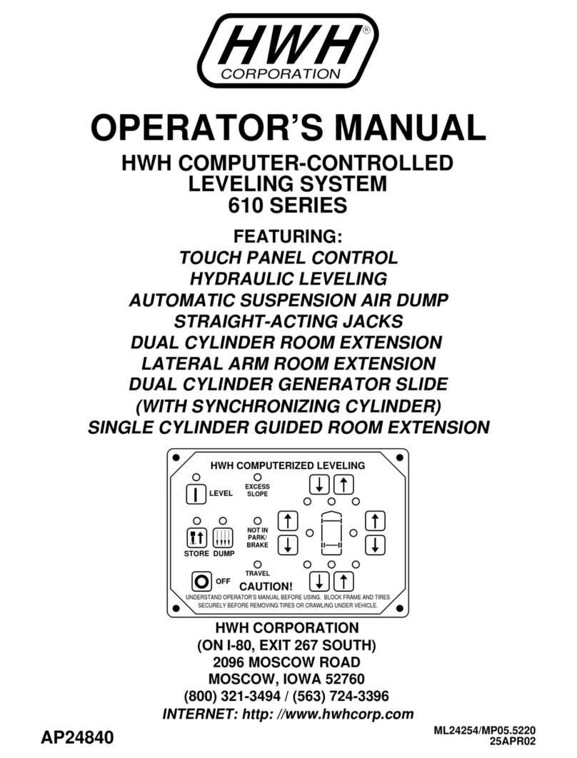
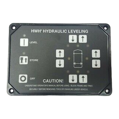
HWH 610 SERIES User manual

H
CORPORATION
H
W
R
FEATURING:
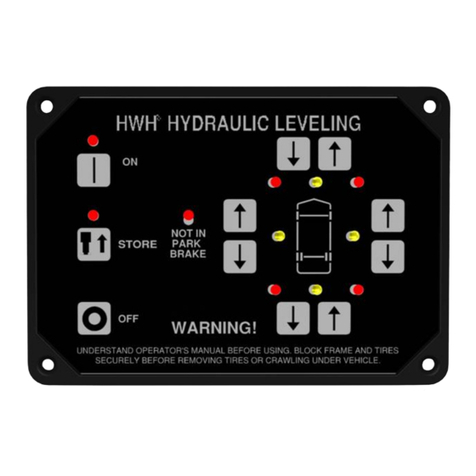
TOUCH PANEL CONTROL
HYDRAULIC LEVELING
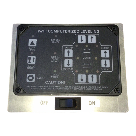
COMPUTER-CONTROLLED LEVELING SYSTEM
OPERATOR’S MANUAL
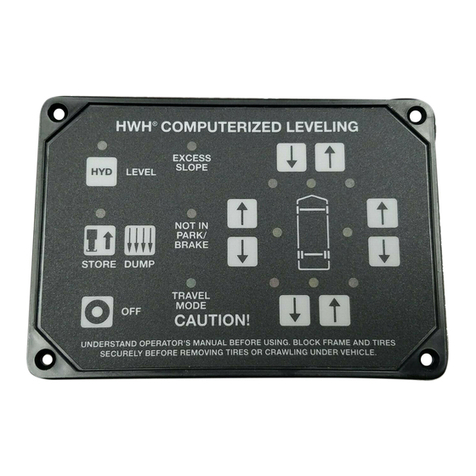
HYD
LEVEL
SECURELY BEFORE REMOVING TIRES OR CRAWLING UNDER VEHICLE.
UNDERSTAND OPERATOR’S MANUAL BEFORE USING. BLOCK FRAME AND TIRES
CAUTION!
OFF
NOT IN
EXCESS
SLOPE
PARK/
BRAKE
STORE
ML0036/MP05.4518
18MAY01
AIR LEVELING
TWO FRONT HWH JACKS ONLY
AIR
HWH COMPUTERIZED LEVELING
JET AIR SUSPENSION
COMBINATION HYDRAULIC/AIR LEVELING
610 SERIES
(ON I-80, EXIT 267 SOUTH)
INTERNET: http: //www.hwhcorp.com
(800) 321-3494 / (563) 724-3396
MOSCOW, IOWA 52760
2096 MOSCOW ROAD
HWH CORPORATION
AP19657

CAUTION !
READ THE ENTIRE OPERATOR’S MANUAL BEFORE OPERATING.
MOVE FORWARD OR BACKWARD WITHOUT WARNING CAUSING INJURY OR DEATH.
EXTENSION.
CAUSING INJURY OR DEATH.
CHIPS, OIL LEAKS, ETC. FOLLOW ALL OTHER APPLICABLE SHOP SAFETY PRACTICES.
OPERATOR’S MANUAL
MP15.4502
30MAY01
BLOCK FRAME AND TIRES SECURELY BEFORE CRAWLING UNDER VEHICLE. DO NOT USE LEVELING JACKS OR AIR
SUSPENSION TO SUPPORT VEHICLE WHILE UNDER VEHICLE OR CHANGING TIRES. VEHICLE MAY DROP AND/OR
THE JACKS MAY ABRUPTLY SWING UP WHEN THE FOOT CLEARS THE GROUND OR WHEN JACK REACHES FULL
NEVER PLACE HANDS OR OTHER PARTS OF THE BODY NEAR HYDRAULIC LEAKS. OIL MAY PENETRATE SKIN
WEAR SAFETY GLASSES WHEN INSPECTING OR SERVICING THE SYSTEM TO PROTECT EYES FROM DIRT, METAL
KEEP ALL PEOPLE CLEAR OF VEHICLE WHILE LEVELING SYSTEM AND ROOM EXTENSION ARE BEING OPERATED.
HOW TO OBTAIN WARRANTY SERVICE
THIS IS NOT TO BE INTERPRETED AS A STATEMENT OF WARRANTY
HWH CORPORATION strives to maintain the highest level of
customer satisfaction. Therefore, if you discover a defect or
problem, please do the following:
(563) 724-3396 OR (800) 321-3494. Give your name and
coach was purchased, or the date of system installation,
Notify the dealership where you purchased the
vehicle or had the leveling system installed. Dealership
management people are in the best position to resolve
the problem quickly. If the dealer has difficulty solving
the problem, he should immediately contact the Customer
Service Department, at HWH CORPORATION.
If your dealer cannot or will not solve the problem,
notify the Customer Service Department:
HWH CORPORATION 2096 Moscow Rd. Moscow IA. 52760
address, coach manufacturer and model year, date the
SECOND:
FIRST:
authorization of an independent service facility, to be
defective part, either by appointment at the factory or by the
CORPORATION will authorize repair or replacement of the
determine whether or not your claim is valid. If it is, HWH
HWH CORPORATION personnel will contact you to
during business hours (8:00 a.m. till 5:00 p.m. c.s.t.).
description of the problem, and where you can be reached
determined by HWH CORPORATION. All warranty repairs
must be performed by an independent service facility
authorized by HWH CORPORATION, or at the
HWH CORPORATION factory, unless prior written approval
has been obtained from proper HWH CORPORATION
personnel.

CONTROL IDENTIFICATION
MP25.4555
02NOV98
CONTROL FUNCTIONS
INDICATOR LIGHTSCONTROLS
HYD
LEVEL
SECURELY BEFORE REMOVING TIRES OR CRAWLING UNDER VEHICLE.
UNDERSTAND OPERATOR’S MANUAL BEFORE USING. BLOCK FRAME AND TIRES
CAUTION!
OFF
NOT IN
EXCESS
SLOPE
PARK/
BRAKE
STORE
AIR
HWH COMPUTERIZED LEVELING
EXCESS SLOPE
LIGHT
NOT IN PARK/BRAKE
LIGHT
REAR SUSPENSION
CONTROL
LIGHT
REAR SUSPENSION
BUTTON
HYDRAULIC OPERATION
LIGHT
HYDRAULIC START
BUTTON
JACK STORE
LIGHT
JACK STORE
BUTTON
OFF BUTTON
RAISE LEFT SIDE
BUTTON
LOWER FRONT
BUTTON
RAISE FRONT
BUTTON
JACK DOWN
LIGHT (2-Red)
LEVEL SENSING
LIGHT (4-Yellow)
RAISE RIGHT SIDE
BUTTON
LOWER RIGHT SIDE
BUTTON
"REAR SUSPENSION"
WARNING LIGHT
(2-Red)
RAISE REAR
BUTTON
LOWER REAR
BUTTON
LOWER LEFT SIDE
BUTTON
"HYDRAULIC START" Button
matic hydraulic leveling system.
"REAR SUSPENSION" Button
rear suspension control on.
"JACK STORE" Button
leveling system.
"OFF" Button
"RAISE AND LOWER" Left side buttons
trol the left rear suspension air bag.
"RAISE AND LOWER" Rear buttons
both rear suspension air bags.
"RAISE AND LOWER" Front buttons
both front jacks.
"NOT IN PARK/BRAKE" Indicator light
the control panel is "ON" and the hand/auto park brake is not
set.
"EXCESS SLOPE" Indicator light
the leveling system cannot level the coach.
"REAR SUSPENSION CONTROL" Indicator light
indicates the manual rear suspension control is operable.
"HYDRAULIC OPERATION" Indicator light
cates hydraulic leveling is on.
"JACK STORE" Indicator light
ic retracting is operating.
"JACK DOWN" Indicator light
jacks are vertical.
"LEVEL SENSING" Indicator light
front, rear, right or left side is low.
"REAR SUSPENSION" Warning light
the rear axle position control will NOT function at this time.
- This button turns the manual
- This button operates the auto-
- This button automatically retracts the
- This button turns the panel off.
- These buttons con-
- These buttons control
- This light is on when
- This light comes on when
- This light
- This light indi-
- This light indicates automat-
- These lights indicate the front
- These lights indicate the
- These lights indicate
"RAISE AND LOWER" Right side buttons
control the right side rear suspension air bag.
- These buttons

OPERATING PROCEDURES
MP35.4527
02NOV98
GENERAL INSTRUCTIONS
PREPARATION FOR TRAVEL
For normal travel the "REAR SUSPENSION CONTROL" should
be OFF. The "REAR SUSPENSION WARNING LIGHTS"
should be OFF. If these lights are ON the automatic rear axle
position control will NOT function.
Park with the front of the vehicle facing downhill if possible.
If parking on soft ground or asphalt paving, wood blocks or
pads must be placed under the jacks.
Any time a hydraulic leveling process is interrupted, retract the
jacks according to the "JACK RETRACTION" section and then
restart the leveling process.
If the hand/auto brake is not set when the (HYD) button is
pressed, the "NOT IN PARK/BRAKE" light will come on and
the hydraulic leveling system will not operate. The light will
remain "ON" only while the "HYD" button is pressed. "REAR
SUSPENSION CONTROL" will function any time the ignition
is "ON" or in the "ACC" position.
Before traveling, the red "JACK DOWN" warning lights must
be off. The master "JACK DOWN" warning light on the dash
should be off. If the lights are not correct for travel, retract the
jacks as described in the "JACK RETRACTION" section. The
"REAR SUSPENSION WARNING LIGHTS" should be "OFF".
If these lights are "ON" the automatic rear axle position con-
trol will NOT function.
CAUTION:
SYSTEM OPERATION
AUTOMATIC HYDRAULIC/AIR LEVELING
1. Place the transmission in the recommended position for
parking and set the parking brake. Turn the ignition to the "ACC"
or "ON" position.
2. Press the "HYDRAULIC START" (HYD) button. This will
place the system in the hydraulic/air operation mode. The "HY-
DRAULIC OPERATION" indicator light will glow steady.
3. Press the "HYDRAULIC START" button a second time. The
"HYDRAULIC OPERATION" light will start to flash. The left
front jack will lower to the vertical position, then the right front
jack will lower to the vertical position. As the jacks lower to the
vertical psition their respective "JACK DOWN" indicator light
will come on. The two "REAR SUSPENSION WARNING
LIGHTS" will come on. The dash mounted "JACK DOWN" warn-
ing lights and the "WARNING MANUAL MODE" light will come
"ON". The pump will shut off and the "HYDRAULIC OPERA-
TION" light will glow steady. At this time, the operator should
check to make sure the jacks are vertical and place pads under
the jacks if the ground will not support the vehicle.
4. Press the "HYDRAULIC START" button a third time. The
"HYDRAULIC OPERATION" light will start to flash. The coach
is then automatically leveled utilizing the rear suspension air
bags and the front hydraulic jacks. The rear suspension air
bags will inflate or deflate to do as much of the leveling as pos-
sible before the front jacks are utilized. If not used for leveling,
the front jacks will be extended to the ground to help stabilize
the coach. In the event the jacks and/or the rear suspension
air bags are unable to level the coach, the "EXCESS SLOPE"
indicator light will come "ON". One or two yellow lights will re-
main "ON". The leveling process may take as long as four to
five minutes if an excess slope is involved.
5. After a pause of ten (10) seconds, the system will auto-
matically shut off. (The dash mounted "JACK DOWN" warn-
ing light will remain "ON" as long as the ignition is in the "ON"
or "ACC" position and the front jacks are in the vertical pos-
ition.)
6. Turn the iginition switch to the "OFF" position.
DO NOT RELY SOLELY UPON THE WARN-
ING INDICATOR LIGHTS. IT IS THE OPERATOR’S RE-
SPONSIBILITY TO VISUALLY CHECK THAT ALL JACKS ARE
UP AND THE VEHICLE IS AT THE PROPER RIDE HEIGHT
BEFORE MOVING THE VEHICLE.

OPERATING PROCEDURES
MP35.4572
02NOV98
JACK RETRACTION
1. The operator must be sure that there are no objects under
the vehicle and that all people are clear of the vehicle.
2. Turn the ignition switch to the "ON" or "ACC" position. Press
the "HYDRAULIC START" button. The "HYDRAULIC OPER-
ATION" indicator light will glow steady.
3. Press the "JACK STORE" (STORE) button. The "JACK
STORE" indicator light will start to flash. As the two front jacks
retract to the horizontal position, the respective "JACK DOWN"
indicator light on the touch panel will go out. When both front
"JACK DOWN" lights are out, the two "REAR SUSPENSION
WARNING LIGHTS" will go out. The automatic rear suspen-
sion control will now function. The dash mounted "JACK DOWN"
warning light will go out. The "WARNING MANUAL MODE"
indicator light will be "OFF". The coach may now be moved.
The "JACK STORE" indicator light will continue to flash.
4. The system will continue to "retract" for six minutes, then
automatically shut off. If a "JACK DOWN" indicator light stays
on the system will continue to retract for thirty (30) minutes
then shut off regardless of warning lights.
IMPORTANT:
Do not interrupt power to the system until the
system automatically shuts off.
5. If the jacks cannot be retracted by this procedure, see "MANUAL
JACK RETRACTION" section.
MANUAL HYDRAULIC OPERATION
1. Place the transmission in the recommended position for
parking and set the parking brake. Turn the ignition to the "ACC"
or "ON" position.
2. Press the "HYDRAULIC START" button. This will place the
system in the hydraulic/air operation mode. The "HYDRAULIC
OPERATION" indicator light will glow steady.
3. Press the "HYDRAULIC START" button a second time. The
"HYDRAULIC OPERATION" light will start to flash. The left
front jack will lower to the vertical position, then the right front
jack will lower to the vertical position. As the jacks lower to the
vertical position, their respective "JACK DOWN" indicator light
4. The vehicle may be leveled using the manual raise and lower
buttons on the right half of the panel. (Refer to the Control Ident-
ification and Function page.) If a yellow "LEVEL SENSING"
indicator light is "ON", that side or end of the vehicle is low.
Right to left leveling is done with the rear suspension air bags.
If the front yellow light is on, it is best to lower the rear of the
vehicle first. If the front light remains on, extend the two (2)
front jacks until the front yellow light goes out. If not used for
leveling, the two front jacks may be extended to the ground to
help stabilize the coach.
IMPORTANT:
Do not continue to push the front raise button
for more than ten (10) seconds after the jacks are fully extended.
5. Turn the ignition switch to the "OFF" position.
MANUAL AIR OPERATION
1. The manual "REAR SUSPENSION CONTROL" (manual
air operation) will operate any time the ignition switch is in the
"ACC" or "ON" position. This function can be used to level the
coach without the front jacks being lowered to the vertical pos-
ition.
2. Press "REAR SUSPENSION CONTROL" (AIR) button. "REAR
SUSPENSION CONTROL" indicator light will come "ON" steady.
The "WARNING MANUAL MODE" indicator light (in dash) will
come "ON". The two (2) red "REAR SUSPENSION WARN-
ING LIGHTS" on the touch panel will come "ON".
NOTE:
At this point, the automatic rear axle position control
will not function.
3. Use the up and down arrow on the right side of the touch
panel to inflate or deflate the rear suspension air bags. Only
the right, left, and rear raise and lower buttons will operate at
this time. Level the coach according to the yellow "LEVEL
SENSING" indicator lights.
4. Pushing the "OFF" button will return the coach to the auto-
matic rear axle position control. Turn the ignition switch to the
"OFF" position.
will come "ON". The dash mounted "JACK DOWN" warning
light and the "WARNING MANUAL MODE" light will come "ON".
The pump will shut off and the "HYDRAULIC OPERATION"
light will glow steady. At this time, the operator should check
to make sure the jacks are vertical and place pads under the
jacks if the ground will not support the vehicle.

OPERATING PROCEDURES
MP35.4577
02NOV98
MANUAL JACK RETRACTION
1. Use the valve release "T" handles for retracting only if the
"STORE" button on the control panel will not retract the jacks
for travel.
CAUTION:
KEEP AWAY FROM THE WHEELS, DO
NOT CRAWL UNDER COACH, KEEP A SAFE DISTANCE IN
FRONT AND REAR OF VEHICLE. THE VEHICLE MAY DROP
AND/OR MOVE FORWARD OR BACKWARD WITHOUT
WARNING OR AS THE VALVE RELEASE IS OPERATED.
2. Locate the 2 valve release "T" handles on the solenoid valves.
The solenoid valves are located on the pump/manifold assem-
bly. (See the Hydraulic Line Connection Diagram.)
3. Allow clearance for coach to lower.
4. Open the two valves slowly by turning counter clockwise.
The handles may turn easily at first but as an internal spring
is compressed, turning may become more difficult. The valves
need only to be opened enough to retract the jack.
5. Check that both jacks are now retracted.
6. Close the valves by turning the release handles clockwise.
Once the internal spring tension has been released, the handles
will turn free for several turns. DO NOT tighten the handles
past this point as internal damage may occur to the solenoid.
7. The system should not be repaired before being used again.

MAINTENANCE
MP45.4530
30JAN01
SERVICING OF LEVELING SYSTEM
The oil should be checked when the vehicle is first purchased
and then once every two years. More often if there is an oil
leak in the system.
VISUAL INSPECTION
OPERATIONAL CHECK
"NOT IN PARK/BRAKE" CHECK
Review operator manual and confirm that the system is operating correctly.
FLUID: HWH Specialty Hydraulic Oil is recommended. In an
brake fluid or hydraulic jack fluid. Use of these can damage
and can cause staining should a leak occur. DO NOT USE
Dexron automatic transmission fluid contains red dye
emergency Dexron automatic transmission fluid can be used.
seals.
NOTE:
Retract the two front leveling jacks before checking oil level.
Locate the pump/manifold assembly and clean any dirt away
from the breather/filler cap on the oil reservoir. Check that
the oil is within one (1) inch of the top of the reservoir.
Periodically inspect the leveling jacks for damaged or
missing parts such as pivot bolts, springs, roller bearings or
stops. Check the hydraulic lines and wiring for damage and
wear.
Check that the jacks do not interfere with any part of the
vehicle when they are in the horizontal position.
Set park brake. Switch ignition to "ACCESSORY" position.
Continuously press (HYD) button on touch panel to turn on
system. Release parking brake and confirm that the "NOT
IN PARK/BRAKE" indicator light comes on. Reset parking
brake. Switch ignition to "OFF" position.
NOTE: If any of the above checks or inspections reveal a
problem or if there are other problems or questions, consult
a qualified RV repair center, your vehicle or coach
manufacturer, or HWH Corporation for service or repair.

LF RF
FRONT
LEFT
FRONT RIGHT
FRONT
PUMP
MOTOR
SOLENOID
MANIFOLD
EMERGENCY
VALVE RELEASE
PUMP/MANIFOLD
ASSEMBLY
NOTE: BEFORE OPERATING EMERGENCY
VALVE RELEASE, READ AND UNDERSTAND
PROCEDURE FOR EMERGENCY RETRACT IN
OPERATORS INSTRUCTIONS.
"T" HANDLES
HYDRAULIC LINE
CONNECTION DIAGRAM
MP65.4530
02NOV98
SHUTTLE VALVE

12 VOLT D.C.
HYDRAULIC
POWER UNIT
MRELIEF VALVE
RETURN PRESSURE SOLENOID MANIFOLD
ASSEMBLY
CHECK
VALVE
INNER
CHECK
VALVE
OUTER
SOL.VALVE SOL.VALVE
RFLF
PRESSURE/
RETURN
SHUTTLE
VALVE
ACTUATOR
RIGHT
FRONT
LEFT
FRONT
HYDRAULIC SCHEMATIC
BI-AXIS LEVELING SYSTEM WITH KICK-DOWN JACKS
MP65.4535
02NOV98

TOUCH
PANEL
LF RF
HYDRAULIC HARNESS
BLUE (L.F.)
GREEN (R.F.)
MANIFOLD WIRING DIAGRAM
* FUSE MAY BE REQUIRED.
CHECK APPLICABLE CODE.
FRONT
RED
WHITE
BUTT CONNECTORS
BLUE WIRE FROM PUMP HARNESS
NOTE:
GROUND THIS WIRE
BEFORE APPLYING
POWER TO BOX.
FOR MANIFOLD AND PUMP
PRESSURE SWITCH
HARNESS
TO "BRAKE"
LIGHT ON DASH.
TO PARK
BRAKE SWITCH
SENSING
UNIT
INTERRUPT WIRE FROM BRAKE
SWITCH TO BRAKE LIGHT
END OF
RESERVIOR
JACK WARNING/
PLUG INTO JET AIR
SYSTEM HARNESS
NOT USED
NOT USED
10 AMP
5 AMP
10 AMP
5 AMP
5 AMP 5 AMP
RED (ACC.)
BLACK(FROM HARN.) BOX
REAR BOX
FRONT
(9 PIN UML)
JACKS DOWN LIGHT
3 PIN
UML CONNECTOR
FOR DASH CONNECTOR
1
2
3
1
2
3
4
5
6
7
8
9
MODULAR
CABLE
5 AMP
5 AMP
5 AMP
ELECTRICAL CONNECTION DIAGRAM
FOR JET AIR SYSTEM
WHITE 14 GA.
MP85.4553
02NOV98
GROUND WARNING
SWITCH WITH HOSE
CLAMP
WARNING SWITCH
(SCREWED OR
CLAMPED TO JACK.)
PRESSURE SWITCH
IN REAR. PLUGS INTO
WARNING SWITCH.
HYDRAULIC HARNESS
FOR MANIFOLD AND PUMP
BLACK 10 GA.
(WITH 60 AMP FUSE)
GRAY (PUMP
SOLENOID)
TO PUMP
MOTOR
RED
(M.S.)
*FROM
BATTERY
SOLENOID
AND PRESSURE
SWITCH GROUND
PUMP WIRING DIAGRAM

5 AMP
10 AMP
10 AMP
5 AMP
5 AMP
5 AMP
5 AMP
5 AMP
CONNECTION INFORMATION
JET AIR SYSTEM
5 AMP
#10 BLACK
POWER WIRE
PART & SERIAL NUMBER
WHITE - GROUND
YELLOW - LS
BLACK - FRONT
GREEN - RS
RED - REAR
MODULAR CABLE INPUT
POSITIVE VOLTAGE
LF WHITE
RF RED
WARNING SWITCH
INPUTS
MP85.4558
02NOV98
GREEN - RIGHT FRONT
BLUE - LEFT REAR LOWER
RIGHT SIDE DOWN FUSE
BLUE - LEFT FRONT
YELLOW - WARNING
MANUAL INDICATOR
RED - RIGHT SIDE
DOWN
PUMP FUSE
ACC. FUSE
RED - MASTER RELAY
BLUE - PARK BRAKE SWITCH
GRAY - PUMP RELAY
JACKS DOWN
WARNING LIGHT
OUTPUT
LEVEL SENSING
UNIT INPUTS

BOX
CONTROL
SENSOR
LEVEL
PANEL
TOUCH
PUMP
LFRF
Supply
uP
FET
FETFETFET
OFF
SWITCHES
WARNING
HYD
uP
CR1
GND
CR1-1
RED
CR2-1
MS
+12V.
COACH
BATTERY MS
HAND/AUTO
BRAKE
NOT SET
NOTES:
1. Wire to Hand/Auto switch
is to be cut. Rewire using
butt connectors as shown.
Note the direction of the
diode and the blue wire
entering the sleeve.
12V.
CHASSIS
GROUND
CR2-2
15 AMP
300A. 60A.
BLACK
#10
WHITE
14GA.
ACC.
IGN.
B
BRAKE
SWITCH
BLUE WIRE FROM
PUMP\MS HARN.
NEG. ACTIVATED PARK
CR2
MUST BE FUSED
@ 5 AMP. MIN.
15 AMP. MAX.
+12 V ACC.
TP SUPPLY
5 AMP
5A
+12v
AP9800
10A 10A
FET FET FET FET
GREEN
BLUE
GRAY
5A 5A 5A 5A
LR
RAISE LR
LOWER RR
RAISE RR
LOWER
YELLOW BLUE GREEN RED
POWER TO JET AIR CR3-1
PRESSURE
SWITCHES
5A
FET
AIR
CR3
uP
JACKS
DOWN
WARNING
MANUAL
INDICATOR
RED 14GA.
AMP
YELLOW
123
456
789
*
987
654
3211
2
3
4
5
6
7
8
9
1
2
3
1-480706-0 HOUSING
W/ 8 350538-1 PINS
1-480700-0 HOUSING
W/ 3 350538-1 PINS
AMP
AMP
LF RF YELLOW
BLUE RED GREEN
GREEN BLUE
6
5
4
3
2
1
1
2
3
6
5
4
ORANGE
WHITE
PURPLE
YELLOW
MP85.4568
02NOV98
ELECTRICAL SCHEMATIC
Other manuals for 610 SERIES
5
Table of contents
Other HWH Control System manuals