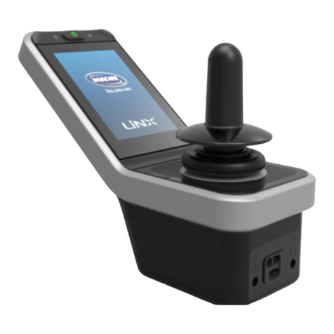
Invacare LiNX User manual

©2020InvacareCorporation
Allrightsreserved.Republication,duplicationormodicationinwholeorinpartisprohibitedwithoutpriorwritten
permissionfromInvacare.Trademarksareidentiedby™and®.AlltrademarksareownedbyorlicensedtoInvacare
Corporationoritssubsidiariesunlessotherwisenoted.
Invacarereservestherighttoalterproductspecicationswithoutfurthernotice.
MakingLife'sExperiencesPossibleisaregisteredtrademarkintheU.S.A.

Contents
1General.........................................5
1.1AboutThisManual.............................5
1.2Symbolsinthismanual..........................5
1.3GeneralInformation............................5
1.4ImagesinThisManual..........................5
2Safety..........................................6
2.1Safetyinformation..............................6
2.2Safetynotesontheelectricalsystem................6
3Assembly........................................7
3.1TighteningTorques.............................7
3.2Imperialtometricconversionchart.................7
3.3OverviewComponents..........................8
3.4Powermodulemounting.........................11
3.5Mountingpositionsonwheelchairs.................12
3.6Portpin-outs..................................13
3.7ActuatorPortCongurations(FactorySetup)..........13
3.7.1PortcongurationsforsystemswithDLX-REM2xx
(EU-VersionwithModuliteseat)................14
3.7.2Portcongurationfornon-expandablesystems(US
version)..................................15
3.7.3PortcongurationforsystemswithDLX-REM400
andDLX-REM500(withUltraLowMaxxseat)......16
3.7.4PortCongurationsforFunctionkeys..............17
3.8WiringDiagrams...............................17
3.8.1WiringforModuliteSeatingSystem..............18
3.8.2WiringforModuliteSeatingSystem(ProntoM41
Only)....................................25
3.8.3WiringforModuliteSeatingSystem(FoxOnly)......26
3.8.4WiringforUltraLowMaxxSeatingSystem.........29
3.9Mountingtheprimaryremotes....................32
3.9.1MountingDLX-REM1XXandDLX-REM2XXfor
Modulite.................................32
3.9.2MountingDLX-REM2XXforUltraLowMaxx........33
3.9.3MountingtheDLX-REM400....................36
3.9.4MountingToggleSwitchesontheDLX-REM400......38
3.9.5MountingDLX-REM500toSwing-AwayRemote
Holder...................................38
3.10MountingPrimaryRemotestoNucleusMidline
Holder.....................................39
3.11Mountingthesecondaryremotes.................40
3.11.1MountingKLICKxAdapterforIDC..............40
3.11.2MountingtheDLX-ACU200....................40
3.11.3MountingtheDLX-CR400.....................42
3.11.4MountingtheDLX-REM050....................43
3.12MountingtheASLcomponents...................43
3.12.1MountingInterfaceBoxes.....................43
3.12.2MountingtheCompactSingleSwitchJoystick......46
3.12.3MountingtheMicroExtremityControlJoystick.....47
3.12.4MountingthePediatricCompactJoystick.........49
3.12.5Mountingtheeclipsetraywithproximity
sensors...................................51
3.13Mountingthe10wayswitch.....................51
3.13.1Mountingthe10wayswitchforModulite........52
3.13.2Mountingthe10wayswitchforUltraLow
Maxx....................................53
3.13.3ChangingLabeling..........................54
4ReplacingWheelchairComponents.....................55
4.1Generalinformationonsetup.....................55
4.2BatterySynchronisationonNewBatteries............55
4.3ReplacingPowerModuleasSparePart..............55
4.4SetupProcedureAfterPowerModuleReplacement.....55
5OverviewLiNXAccesstools..........................57
5.1TheLiNXAccessKey............................57
5.1.1RenameLiNXAccessKey(onlypossiblewithLiNX
AccessPCtool).............................57
5.2OverviewFunctions.............................58
5.2.1OverviewUserPreferences.....................60
5.2.2OverviewDisplaySettings......................64
5.2.3OverviewControlInput/Output(ControlIO).......64
5.2.4ControlInputTypesandOptions................68
6Suggestedprogrammingprocedure....................71
6.1Step1–Power-uptest..........................71
6.2Step2–CheckMotorOrientation..................71
6.3Step3–SetLoadCompensation...................72
6.3.1CalibratingAdaptiveLoadCompensation(iOS
Tool)....................................72
6.3.2CalibratingAdaptiveLoadCompensation(PC
tool).....................................73
6.4Step4–AdjustSpeedSettings....................74
6.5Step5–Adjustaccelerationsettings................75
7UsingtheLiNXAccessiOStool........................77
7.1Navigationbar.................................77
7.1.1Applicationmenu............................77
7.1.2ChangingProgramName......................77
7.2HomeScreen.................................78
7.3Connectioncontextactions.......................78
7.3.1Connecttodevicescreen......................78
7.3.2Readingaprogramfromthewheelchair...........79
7.3.3RestoringDefaultWheelchairCongurations........79
7.3.4ConvertingCongurationFiles..................79
7.3.5ModifyingaProgram.........................79
7.3.6Writingaprogramtothewheelchair.............80
7.3.7Savingprograms............................80
7.3.8UpgradingFirmware..........................81
7.3.9StoringtheLAKcerticate.....................82
7.4Filecontextactions.............................82
7.4.1Loadfromlescreen.........................82
7.4.2WritingBundleFiles..........................82
7.4.3Openingles...............................83
7.4.4Deletingles...............................83
7.4.5E-mailingles..............................84
8ModifyingwheelchaircongurationwithiOStool.........85
8.1ProleAndFunctionActions......................85
8.2Modifyingfunctionandprolenames...............88
8.3Modifyingdriveparametersgraphically..............88
8.4Modifyingdriveparametersnumerically..............89
8.5ModifyingLightingParameters.....................89
8.6ModifyingGyroSupportinDriveFunctions...........90
8.7ModifyingSeatingParameters.....................90
8.8ModifyingAttendantParameters...................92
8.9ModifyingUtilityFunction........................93
8.10JoystickSwitchThreshold........................96
8.11Adjustquadrantoperation.......................96
8.11.1Adjustdrivedirections.......................97
8.12Enableindirectnavigation.......................98
8.13ConguringControlInput/Output(ControlIO)........99
8.13.1ConguringExternalPowerButton.............. 103
8.13.2ConguringToggleSwitches................... 104
8.13.3ConguringMouseClicks..................... 107
8.14Installing/SettingupAlternativeSwitches............ 109
8.15SipandPuffInstallation......................... 110
8.15.1SipandPuffCalibration...................... 110
9UsingtheLiNXAccessPCtool........................ 113
9.1Installingthesoftware........................... 113
9.1.1UsingBluetoothonacomputer................. 114
9.2Layoutoverview............................... 114
9.3Concepts..................................... 115
9.4CheckingandGettingLatestVersion................ 115
9.5Connectioncontextactions....................... 116
9.5.1Connecting/DisconnectingtheLiNXAccessPC
tool..................................... 116
9.5.2Writeaprogramtoawheelchair................ 116
9.5.3Readaprogramfromawheelchair............... 116
9.5.4Saveaprogramasale....................... 117
9.5.5StoringtheLAKcerticate..................... 117
9.5.6UpgradingFirmware.......................... 117
9.5.7RestoringDefaultWheelchairCongurations........ 118
9.5.8LoadingDefaultCongurations.................. 118
9.5.9ConvertingCongurationFiles.................. 119
9.6Filecontextactions............................. 119
9.6.1Open/Closeale............................ 119
9.6.2Removealefromlist........................ 120
9.6.3Writingbundlelestoachair.................. 120

Invacare®LiNX
10ModifyingwheelchaircongurationwithPCtool......... 121
10.1ProleandFunctionActions..................... 121
10.2Modifyingfunctionandprolenames.............. 122
10.3Modifyingdriveparameters...................... 122
10.3.1ModifyingLightingParameters................. 122
10.3.2ModifyingGyroSupportinDriveFunctions........ 123
10.4ModifyingSeatingParameters.................... 123
10.5ModifyingAttendantParameters.................. 126
10.6ModifyingUtilityFunctions...................... 126
10.7JoystickSwitchThreshold........................ 128
10.8SettingupSystemforLatchedDriving.............. 129
10.9Adjustquadrantoperation....................... 130
10.9.1Adjustdrivedirections....................... 131
10.10EnableIndirectNavigation...................... 132
10.11ConguringControlInput/Output(ControlIO)....... 133
10.11.1ConguringExternalSwitches................. 135
10.11.2ConguringExternalPowerButton............. 136
10.11.3ConguringMouseClicks.................... 137
10.11.4ConguringToggleSwitches.................. 137
10.11.5ProgrammingMultipurposeButtons............ 138
10.12Installing/SettingupAlternativeSwitches........... 139
10.13SipandPuffinstallation........................ 139
10.13.1SipandPuffCalibration..................... 140
11Diagnostics...................................... 142
11.1ViewingSystemSummary....................... 142
11.2ViewingActiveErrors........................... 142
11.3ViewingChairStatistics......................... 142
11.4ViewingLiveDiagnostics........................ 144
11.5Clearingtheeventlog.......................... 144
12StructureofProgramNames........................ 145
12.1Where-UsedMatrices.......................... 145
12.2NamingFormat............................... 146
41605129-G

General
1General
1.1AboutThisManual
Thisdocumentisasupplementtothepowerwheelchair’s
documentation.
TheproductitselfdoesnotbearaCEmarkbutispart
ofaproductthatcomplieswiththeMedicalDevice
Regulation2017/745,ClassIconcerningmedicaldevices.
Itisthereforecoveredbythepowerwheelchair’sCE
marking.Seethepowerwheelchair’sdocumentationfor
moreinformation.
Invacarereservestherighttoalterproductspecications
withoutfurthernotice.
Beforereadingthisdocument,makesureyouhavethe
latestversion.YoundthelatestversionasaPDFonthe
Invacarewebsite.
Formoreinformationabouttheproduct,forexample
productsafetynoticesandproductrecalls,contactyour
Invacarerepresentative.Seeaddressesattheendofthis
document.
1.2Symbolsinthismanual
Inthismanual,hazardstatementsareindicatedby
symbols.Thesymbolsareaccompaniedbyasignalword
thatindicatestheseverityoftherisk.
WARNING
Indicatesahazardoussituationthatcould
resultinseriousinjuryordeathifitisnot
avoided.
CAUTION
Indicatesahazardoussituationthatcould
resultinminororslightinjuryifitisnot
avoided.
IMPORTANT
Indicatesahazardoussituationthatcould
resultindamagetopropertyifitisnot
avoided.
Givesusefultips,recommendationsand
informationforefcient,trouble-freeuse.
Thissymbolidentiesalistofvarioustools,
componentsanditemswhichyouwillneedin
ordertocarryoutcertainwork.
1.3GeneralInformation
Serviceandmaintenanceworkmustbecarriedouttaking
thisdocumentintoaccount.
Itisimperativethatyouobservesafetyinformation.
Informationaboutoperationoraboutgeneralmaintenance
andcareworkontheproductshouldbetakenfrom
servicemanual.
Assemblyofaccessoriesmightnotbedescribedinthis
document.Refertothemanualdeliveredwiththe
accessory.Additionalmanualscanbeorderedfrom
Invacare.Seeaddressesattheendofthisdocument.
Youcanndinformationaboutorderingsparepartsin
thesparepartscatalogue.
SparepartsmustmatchoriginalInvacareparts.Onlyuse
sparepartswhichhavebeenapprovedbyInvacare.
Theproductmayonlybemaintainedandoverhauledby
qualiedpersonnel.
Theminimumrequirementforservicetechniciansis
suitabletraining,suchasinthecycleororthopedic
mechanicselds,orsufcientlylong-termjobexperience.
Experienceintheuseofelectricalmeasuringequipment
(multimeters)isalsoarequirement.SpecialInvacare
trainingisrecommended.
Alterationstothemobilitydevicewhichoccurasaresult
ofincorrectlyorimproperlyexecutedmaintenanceor
overhaulworkleadtotheexclusionofallliabilityonthe
sideofInvacare.
Ifyouhaveanyproblemsorquestionscontactyour
provider .
1.4ImagesinThisManual
Thedetailedimagesinthismanualaregivenmarksto
identifyvariouscomponents.Componentmarksintext
andoperationalinstructionsalwaysrelatetotheimage
directlyabove.
1605129-G5

Invacare®LiNX
2Safety
2.1Safetyinformation
WARNING!
Theproceduresinthisservicemanual,mustbe
performedbyaspecializeddealerorqualied
servicetechnician.
–Donothandlethisproductoranyavailable
optionalequipmentwithoutrstcompletely
readingandunderstandingtheseinstructions
andanyadditionalinstructionalmaterialsuch
asusermanuals,installationmanualsor
instructionsheetssuppliedwiththisproduct
oroptionalequipment.
Theinformationcontainedinthisdocumentis
subjecttochangewithoutnotice.
2.2Safetynotesontheelectrical
system
WARNING!
Fireandburnhazardduetoelectricalshorts
–Themobilitydevicemustbecompletely
switchedoffbeforeremovalof
voltage-carryingcomponents.Todo
this,removethebatteries.Forinformation
aboutremovingthebatteries,refertothe
servicemanualoftheparticularwheelchair.
–Avoidshort-circuitingthecontacts
whencarryingoutmeasurementson
voltage-carryingcomponents.
WARNING!
Riskofinjuryordamageduetoelectrical
shorts
Connectorpinsoncablesconnectedtothe
powermodulecanstillbeliveevenwhenthe
systemisoff.
–Cableswithlivepinsshouldbeconnected,
restrainedorcovered(withnon-conductive
materials)sothattheyarenotexposedto
humancontactormaterialsthatcouldcause
electricalshorts.
–Whencableswithlivepinshavetobe
disconnected,forexample,whenremoving
thebuscablefromtheremoteforsafety
reasons,makesuretorestrainorcoverthe
pins(withnon-conductivematerials).
Riskofdamagetotheconnectorpins
Ifyoutouchtheconnectorpins,theycan
becomedirtyortheycanbedamagedby
electrostaticdischarge.
–Donottouchtheconnectorpins.
Tomaximizeperformance,minimizeEMCemissions,
maximizeEMCandESDimmunity,andtokeepthecabling
ofthewheelchairsafeandtidy,observethefollowing
guidelines:
•Allwiringshouldcomplywiththerequirementsof
ISO7176-14.
•Keepallcablesasshortaspossible.
•AllcablesusedshouldberesistanttoretoVW-1
(UL1581)orsimilar .
•Avoidwireloops,especiallyloopsofsinglewires
insteadofwirepairs.
•Trytorunwiresinpairsorbunches.Forexample,
runthebattery'spositiveandnegativewirestogether,
andthemotor'spositiveandnegativewirestogether .
Bindwirestogetherandxthemtothechassis.
•Donotroutethecables(includingthemotorcable)
nearthemotorcase,wherepossible.
•Makesurethatallvehiclesub-frames,particularlythe
motorsandcontrollercase,areelectricallyconnected.
•Donotusethevehicleframeastheearthreturn.Any
electricallow-resistanceconnectiontotheframeisa
safetyriskandisnotallowedbyinternationalsafety
standards.
•Tominimizeelectromagneticemissionsbythemotor
brushes,itmaybenecessarytotcapacitorsbetween
thebrushholdersandthemotorcase.Makesure
thattheleadsarekeptasshortaspossible.Asuitable
capacitoris4n7,2kVCeramic.
•Forbestelectricalperformance,thewiresizemust
beaslargeaspossible,butnolargerthanwhatthe
crimpintheconnectorcanwithstand.Alwaysusethe
correcttoolforcrimping.
•Recommendedminimumwiresizesareshowninthe
wiringsections.
•Forlow-currentsignals,donotusewiresizessmaller
than0.5mm2/20AWG,becausesmallerwiresare
physicallynotstrongenoughforthisapplication.
•Thetypeofcableusedmustbeappropriateforthe
mechanicalandenvironmentalabuseitislikelyto
encounter .
•Donotusedamagedorabusedcables.Adamaged
cablecanpotentiallyproducelocalizedheat,sparksor
arcing,andassuchitcancauseare.
•Protectallcablesagainstpossiblecontactwith
ammablematerial.
•Ifanextensionloomistted,mountitwiththe
femaleconnectorfacinghorizontalordownwards,and
protectitfromdirectsplashing.Iftheextensionloom
istobeusedforfrequentdisconnection,mountthe
femaleconnectorsothatitfacesdownwards.
61605129-G

Assembly
3Assembly
3.1TighteningTorques
CAUTION!
Riskofdamagetomobilitydevicedueto
improperlytightenedscrews,nutsorplastic
connections.
–Alwaystightenscrews,nutsetc.tothestated
tighteningtorque.
–Onlytightenscrewsornutswhicharenot
listedherengertight.
Thetighteningtorquesstatedinthefollowinglistare
basedonthethreaddiameterforthenutsandboltsfor
whichnospecicvalueshavebeendetermined.Allvalues
assumedryandde-greasedthreads.
ThreadTighteningTorquein
Nm±10%
M43Nm
M56Nm
M610Nm
M825Nm
M1049Nm
M1280Nm
M14120Nm
M16180Nm
3.2Imperialtometricconversionchart
Youcanusethischartasanorientationtondtheright
toolsize.
IMPERIALMETRIC
inchmm
5/641.9844
3/322.3813
7/642.7781
1/83.1750
9/643.5719
5/323.9688
11/644.3656
3/164.7625
13/645.1594
7/325.5563
15/645.9531
1/46.3500
17/646.7469
9/327.1438
IMPERIALMETRIC
inchmm
19/647.5406
5/167.9375
21/648.3344
11/328.7313
23/649.1281
3/89.5250
25/649.9219
13/3210.3188
27/6410.7156
7/1611.1125
29/6411.5094
15/3211.9063
31/6412.3031
1/212.7000
33/6413.0969
17/3213.4938
35/6413.8906
9/1614.2875
37/6414.6844
19/3215.0813
39/6415.4781
5/815.8750
41/6416.2719
21/3216.6688
43/6417.0656
11/1617.4625
45/6417.8594
23/3218.2563
47/6418.6531
3/419.0500
49/6419.4469
25/3219.8438
51/6420.2406
13/1620.6375
53/6421.0344
27/3221.4313
55/6421.8281
7/822.2250
1605129-G7

Invacare®LiNX
3.3OverviewComponents
Remotemodules
DLX-REM110
•Drivefunction
DLX-REM211
•Drivefunction
•Poweredseating
function
DLX-REM216
•Drivefunction
•Poweredseating
function
•Lightingfunction
DLX-REM400
•Touchscreeninterface
tofacilitate:
–Multipledrive
functions
–Multiplepowered
seatingfunctions
–Lightingfunction
•Multipurposebuttons
•3.5mmjacksockets
DLX-REM500
•Touchscreeninterface
tofacilitate:
–Multipledrive
functions
–Multiplepowered
seatingfunctions
–Lightingfunction
•Multipurposebuttons
•3.5mmjacksockets
Secondaryremotemodules
LiNXIDC
IntuitiveDualControl
•On/Offbutton
•Speeddial
•Displayfordrive
directionindicator
DLX-CR400
CompactRemote
•On/Offbutton
•Menubutton
•Displayfordrive,
seatingand
connectivityfunctions
DLX-CR400LF
CompactRemoteLow
Force
•Ascompactremote
•Withlowforcejoystick
DLX-ACU200
AttendantControlUnit
•On/Offrespectively
Selectbutton
•Menubutton
•Displayfordriveand
seatingfunctionsand
"who'sincharge"
indication
DLX-REM050
•Attendantcontrolunit
withdrivefunction
81605129-G

Assembly
ASLcomponents
ASL138
ExtremityControlJoystick
ASL133
CompactSingleSwitch
Joystick
ASL130
MicroExtremityControl
Joystick
ASL132
CompactJoystick
ASL109
SipandPuffHeadArray
ASLcomponents
ASL104/ASL104P
HeadArray
ASL106
FourSwitchProximityArray
ASL504
RemoteStopSwitch
WirelessAccessoriesfor
ATOM:
•WirelessMouse
EmulatorASL558
•WirelessTripleSwitch
ReceiverASL557-3
Powermodules
DLX-PM60
•63Amaximumcurrent
•2xbussockets
•DynamicLoad
Compensation
•AdaptiveLoad
Compensation
•Utilityport
•Real-timeclock
DLX-PM75
•78Amaximumcurrent
•2xbussockets
•DynamicLoad
Compensation
•AdaptiveLoad
Compensation
•Utilityport
•Real-timeclock
DLX-PM120
•120Amaximum
current
•2xbussockets
•DynamicLoad
Compensation
•AdaptiveLoad
Compensation
•Utilityport
•Real-timeclock
1605129-G9

Invacare®LiNX
Powermodules
DLX-PM75AL
•78Amaximumcurrent
•2xbussockets
•DynamicLoad
Compensation
•AdaptiveLoad
Compensation
•Utilityport
•2xactuators
•3xlights
•Real-timeclock
DLX-PM120AL
•120Amaximum
current
•2xbussockets
•DynamicLoad
Compensation
•AdaptiveLoad
Compensation
•Utilityport
•2xactuators
•3xlights
•Real-timeclock
LiNXseatingmodulesandinterfaces
DLX-ACT200
•2xactuatorchannels
•2xbusports
•1x6-pingeneral
purposeinput(GPI)
port
•ModulestatusLED
•Actuatorpower
providedthrough
thebus
DLX-ACT400
•4xactuatorchannels
•2xbusports
•1x6-pingeneral
purposeinput(GPI)
port
•ModulestatusLED
•Actuatorpower
providedthrough
thebus
GLM-CONX4
4-wayconnector
•Expansionblockto
connecttoadditional,
multiplemodulesina
LiNXsystem
LiNXseatingmodulesandinterfaces
DLX-IN200
Inputmodule
•DB9connectorfor
proportionaland
switchedinputs
•12V(200mA)power
supply
•Jackinput(stereo)
•2xLiNXbusconnector
•Activityindicator
displayinginput
demands
DLX-IN500
Inputmodule
•DB9connectorfor
proportionaland
switchedinputs
•12V(200mA)power
supply
•Sipandpuffnozzle
•Jackinput(stereo)
•2xLiNXbusconnector
•Activityindicator
displayinginput
demands
DLX-OUT500
Outputmodule
•DB9connectorfor
switchedoutputs
•Jackoutput(stereo)
•2xLiNXbusconnector
•Statusindicator
Buscable;lengthfrom300
upto2500mm
Extensionloom;length640
and900mm
Poweredseatingaccessories
ASL300
Eggswitch
•Momentaryswitch
•Normallyopen
•Monojack
Stereobuttonswitch
•2switches
•Stereojack
Stereotoggleswitch
•Toggleswitch
•Normallyopen
•Stereojack
101605129-G

Assembly
Poweredseatingaccessories
4–waybuttonswitch
•4switches
•DB9connector
4–waytoggleswitch
•4toggledirections
•DB9connector
10–wayswitch
•Hardware-only
modulethatprovides
simple,directaccess
topoweredseating
functions
DLX-FKEY01
•Forsystemswithone
physicalactuator
•Poweredseating
controlthroughegg
switch,stereobutton
switchorstereotoggle
switch
DLX-FKEY02
•Forsystemswith
twoormorephysical
actuators
•Poweredseating
controlthrough4-way
buttonswitchor
4-waytoggleswitch
DLX-GYR100
LiNXG-Tracmodule
•stabilizeswheelchair’s
drivingbehaviour
DLX-USB02
LiNXUSBcharger
•2USBchargerports
•1Achargingcurrent
perport
•Protectiverubber
bungs
DLX-TILT200–A
Anglesensor
•measuresbackrest
angle
3.4Powermodulemounting
Themountingorientationofthepowermodulethatis
speciedbyInvacareperwheelchairmodelmustbekept.
Dimensionsofthepowermodules
DLX-PM60,DLX-PM75,DLX-PM120
DLX-PM75AL,DLX-PM120AL
Correctmounting
ARear
BConnectors
CTop
DBase
Thepowermodulescanbeplacedonitssideoratan
angle.Whenplacingthepowermodulesatanangle,
1605129-G11

Invacare®LiNX
ensurethattheconnectorsBfacingdownwards,sothat
theconnectorrecesseswillnotcollectorretainforeign
matterorliquids.
Incorrectmounting
ARear
BConnectors
CTop
DBase
Testing
TheLiNXsystemmustbefullytestedafterallmodulesand
cableshavebeeninstalled.
3.5Mountingpositionsonwheelchairs
ThepositionsofthepowermodulesAandDLX-ACT200/400Bdependingonwheelchairmodeland—conguration
areshowninthetablebelow.Forfurtherinformationaboutaccesstothecomponents,refertotheService
manualoftheparticularwheelchairmodel.
RearWheelDriveCenterWheelDrive
AVIVARXwithModuliteseatProntoM41,TDXSP2,TDX
SP2narrowbase,TDXSP2
widebasewithModulite
seat
AVIVARXwithUltraLow
Maxxseat
TDXSP2narrowbaseand
TDXSP2widebasewith
UltraLowMaxxseat
Bora/SpectraXTR,Spectra
XTRHDw/olifter/tiltmodule
Bora/SpectraXTR,Spectra
XTRHDwlifter/tiltmodule
121605129-G

Assembly
RearWheelDriveCenterWheelDrive
Fox
Kite,KiteHD
Storm4,Storm4X-plore,
Storm4Max1
Stream1
1noDLX-ACT200/400onStorm4MaxandStream
3.6Portpin-outs
DLX-PM60,DLX-PM75,DLX-PM120
ALiNXcommunicationbus
BMotor/parkbrakeportM1
CBatteryport
DMotor/parkbrakeportM2
EUtilityport
DLX-PM60AL,DLX-PM75AL,DLX-PM120AL
ALiNXcommunicationbus
BMotor/parkbrakeportM1
CBatteryport
DMotor/parkbrakeportM2
EActuatorports
FLightingport
GUtilityport
3.7ActuatorPortCongurations
(FactorySetup)
Actuatorports,propertiesandbehaviorperactuatorare
denedbyInvacare.Youcanchangespeed,directionand
operationmode.Thisisdoneindifferentmenus,referto
8.7ModifyingSeatingParameters,page90.
SeatingMotion
Theseatingmovementiscalledseatingmotion.The
seatingmotiondenestheicondisplayedontheuser
interface,overallspeed,theindividualactuatorsand
theirspeeds.Aseatingmotioncancontroloneormore
actuators.Therearesixseatingmotionsdenedinthe
factoryset-up.
SeatingFunction
Theseatingfunctionistheuserinputanddeneshow
themotionisoperated.
1605129-G13

Invacare®LiNX
The“AL”powermodulesthatfeatureactuatorsand
lights,havetwoactuatorports.Ifrequired,thesystemis
completedwiththeDLX-ACT200orDLX-ACT400,basedon
theconguration.Thefollowingchaptersdetailtheport
set-uppermodule/conguration.
3.7.1PortcongurationsforsystemswithDLX-REM2xx(EU-VersionwithModuliteseat)
ChannelSeatingmotion(Icon)Seatingfunction(Operation)
ATiltProportionalFWD/REV
BReclineProportionalFWD/REV
CRightlegProportionalFWD/REV
DLeftleg/
Center-mounted
legrest
Bothlegs
ProportionalFWD/REV
ELifterProportionalFWD/REV
Portcongurationwithoutlifter
Powermodule
DLX-ACT200
DLX-ACT400
141605129-G

Assembly
Portcongurationwithlifer
Powermodule
DLX-ACT200
DLX-ACT400
3.7.2Portcongurationfornon-expandablesystems(USversion)
Non-expandablesystemsarettedwithexternalswitchesandafunctionkey,tocontrolthepoweredseatingfunctions.For
moreinformationaboutfunctionkeys,refertochapter3.7.4PortCongurationsforFunctionkeys,page17.
Singleactuatorsystems
ChannelSeatingmotion(Icon)Seatingfunction(Operation)
AReclineonlyProportionalFWD/REV
BTiltonlyProportionalFWD/REV
BLNXonlyProportionalFWD/REV
1605129-G15

Invacare®LiNX
Twoactuatorsystems
ChannelSeatingmotion
(Icon)
Seatingmotion
(Icon)
Seatingmotion
(Icon)
Seatingmotion
(Icon)
Seatingmotion
(Icon)
Seating
function
(Operation)
ATiltTiltReclineLeftlegReclineProportional
FWD/REV
BLifterLNXLNXRightlegTiltProportional
FWD/REV
3.7.3PortcongurationforsystemswithDLX-REM400andDLX-REM500(withUltraLowMaxxseat)
ChannelSeatingmotion(Icon)Seatingfunction(Operation)
ATiltProportionalFWD/REV
BLifterProportionalFWD/REV
CLegrestrightProportionalFWD/REV
DLegrestleftProportionalFWD/REV
161605129-G

Assembly
ChannelSeatingmotion(Icon)Seatingfunction(Operation)
ELNXProportionalFWD/REV
FReclineProportionalFWD/REV
3.7.4PortCongurationsforFunctionkeys
Ifthesystemisinstalledwithanexternalswitchtocontrolthepoweredseatingfunctions(excepta10–wayswitch),a
functionkeyisanoptiontointerfaceswitches.Therearetwodifferentcongurationsoffunctionkeys.Thetypeof
functionkeydeterminesthebehaviourofthesysteminregardstothecontrolofactuators.Propertiesandbehaviourper
switcharedenedbyInvacareandcanbereassignedviatheporttowhichthecontrolinputisconnected.Reassigningis
doneintheCONTROLINPUTS/OUTPUTSsectionoftherespectivemodule.See10.11.1ConguringExternalSwitches,
page135 .
Type1:SingleActuatorSystem(SAS)
Thisfunctionkeyisforsystemswithonephysicalactuator .Itisavailableinoneconguration:
•FKEY01TDC:actuatorcontrolthroughswitchesandjoystick
Externalswitchestocontrolthepoweredseatingfunctions,mustbepluggedintotheJacksockets,seetablebelow.
AMonojacktoconnecteggswitch
BStereojacktoconnectstereobuttonswitchorstereotoggleswitch
Type2:Multi-ActuatorSystem(MAC)
Thisfunctionkeyisforsystemswithtwoormorephysicalactuators.Itisavailableinoneconguration:
•FKEY02TDC:actuatorcontrolthroughswitchesandjoystick
The4–waybuttonswitchorthe4–waytoggleswitchmustbepluggedintotheDB9socket.
3.8WiringDiagrams
Thefollowingdiagramsshowthewiringforawheelchairinacomplexcongurationincludingmultipleactuators,
lightsandattendantcontrolunit.
Toidentifytherequiredcablelength,seetablesbelowormeasurethecableafterremovingit.
1605129-G17

Invacare®LiNX
3.8.1WiringforModuliteSeatingSystem
WiringforModulite:Lifter,Tilt,Recline,PoweredElevatingLegrests,Lights,DualControl,SecondaryInput,DLX-ACT400,
GLM-CONX4(2x),DLX-IN200andUSBCharger
Fig.3-1
Cablelengthmayvarydependingonmountingpositionsofprimaryandsecondaryremotesandof4–wayconnector
GLM-CONX4.
ModelA A
AB B
BC C
CD D
DE E
E
Kite2500mm1500mm300mm700mm700mm
SpectraXTR2HD,
Bora/SpectraXTRStandard
1700mm1700mm300mm700mm700mm
TDXSP21500mm1200mm300mm300mm700mm
Storm4,
Storm4X-plore
1500mm1200mm300mm500mm300mm
AVIVARX1500mm1500mm300mm300mm700mm
181605129-G

Invacare®LiNX
WiringforModulite:Lifter,Tilt,Recline,PoweredElevatingLegrests,Lights,DualControl,DLX-ACT400,GLM-CONX4and
USBCharger
Fig.3-2
Cablelengthmayvarydependingonmountingpositionsofprimaryremote,dualcontrolandof4–wayconnector
GLM-CONX4.
ModelA A
AB B
BC C
CD D
DE E
EF F
F
Kite2500mm1500mm700mm1700mm700mm700mm
SpectraXTR2HD,
Bora/SpectraXTRStan-
dard
1700mm1200mm700mm1500mm700mm700mm
TDXSP21500mm1000mm300mm1500mm700mm300mm
201605129-G
Other manuals for LiNX
2
Table of contents
Other Invacare Control System manuals