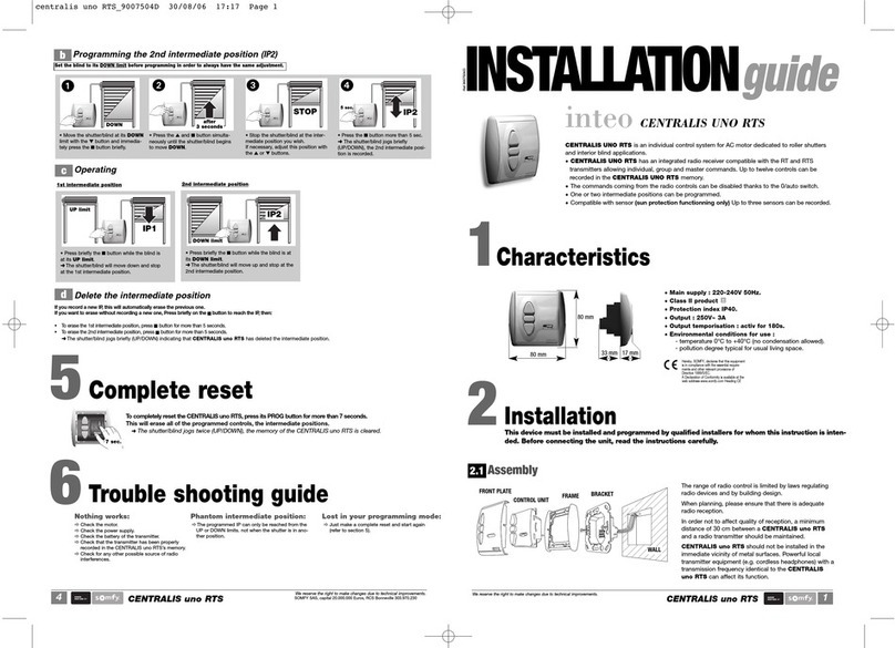
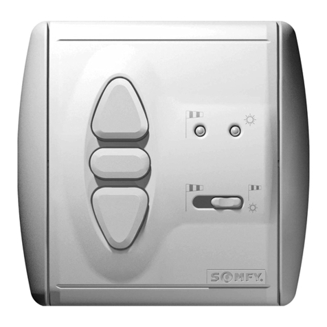
SOMFY Rollixo RTS User manual

Quick Commissioning Guide HW
Rolli o RTS

2
Inhoudsopgave

3
Inhoudsopgave
Rollixo RTS Solutions Page 3
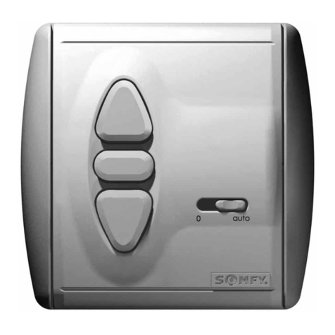
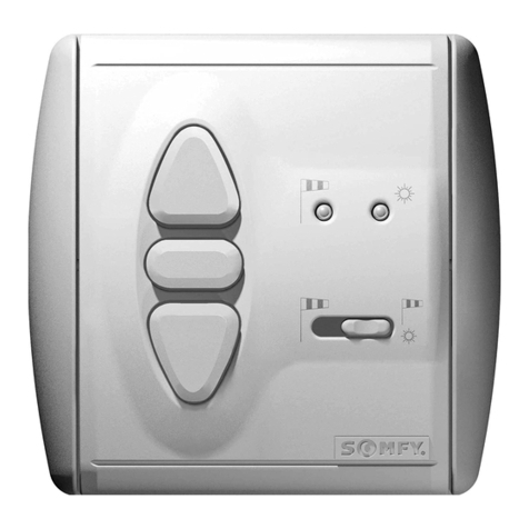
Rollixo RTS Control Panel Overview Page 4
Rollixo RTS Control Panel Mounting Page 4
Somfy RDO Motor Wiring Page 4
Safety Brake Wiring & Powering Up Rollixo RTS Page 5
Somfy RDO Motor Direction of Rotation Setting Page 6
Somfy RDO Motor Limit Setting Page 7
OSE Safety Edge Hard Wired Connexion Page 8
Pairing Keygo RTS keyfob’s Page 8
Locking out the Panel Page 9
Deleting Controls/Transmitters Page 10
Complete Check List Page 11
More information from fitters guides to marketing brochures and videos
Please visit www.Rollixo.co.uk
Contents

4
This quick guide provides basic installation and commissioning guidance based on the Somfy
Rollixo RTS controller and safety edge solutions. Refer to the main Rollixo RTS controller and
safety edge installation guides where more in-depth information relating to the installation
procedure of the Rollixo RTS system is required.
Rollixo RTS Safety Edge Solutions
There is one Somfy hardwired safety edge solution available with the Rollixo RTS:
Rollixo RTS OSE - OSE stands for ‘Optical Safety Edge’.
This is supplied with a safety edge via a hard wired spiral cable and is connected to a Somfy optical
safety edge system. The optical safety edge consists of two optical cells mounted at each end of a
rubber profile. The cells project an optical beam through a hollow section of the profile, it becomes
obscured once the rubber profile is depressed. This in turn results in a signal from the safety edge,
indicating that an obstacle has been detected.
Aditional steps must be taken to ensure the straight edge of the door meets with the straight edge of a
floor extending into the guides. Failure to do so will result in; air + light gaps, false activations of the edge
etc.
“Please refer to the Installer Guide provided
with every Rollixo, here you will find the
basic principles and operating parameters
for any CE compliant safety edge system”
L1 L2N
M
1 2 3 4
Bleu
Marron
Noir
Green/Yellow
Brown
Blue
Black
L1 L2N
M
1 2 3 4
Bleu
Marron
Noir
Sec
Safety EdgeStop
K
5 6 7 8 9 1
Green/Yellow
Brown
Blue
Black
Sec
Safety EdgeStop
K
5 6 7 8 9 1
Connect the motor wires into terminals 1,
2, 3 and 4 as illustrated above.
Note: The motor direction can be reversed during the
commissioning procedure.
Secure the motor supply cable in
place with the cable clamp.
Rollixo RTS Solutions
Somfy motor wiring
✓
✗

5
3 421
Prog
L1 L2N
M
1 2 3 4
Bleu
Marron
Noir
Sec
Safety EdgeStop
K
5 6 7 8 9 1
Green/Yellow
Brown
Blue
Black
Sec
Safety EdgeStop
K
5 6 7 8 9 1
L1 L2N
M
1 2 3 4
Bleu
Marron
Noir
Sec
Safety EdgeStop
K
5 6 7 8 9 1
Green/Yellow
Brown
Blue
Black
Sec
Safety EdgeStop
K
5 6 7 8 9 1
Connect the electrical safety brake
into terminals 5 and 6.
Use the link provided to
connect terminals 5 and 6
3 421
Prog
STOP
Unfold the aerial so that it
points vertically downwards.
Screw the bulb supplied
into the light fitting.
3 421
Prog
STOP
3 421
Prog
STOP
3 421
Prog
STOP
Refit the panel cover and
secure with the screw.
Plug in the supply cable and connect
the the mains supply.
3 421
Prog
STOP
Refit the courtesy
light cover.
3 42
1
Prog
STOP
3 4
2
1
Prog
STOP
If the motor LED comes on, check the safety brake or link
connection.
If the safety edge LED comes on, the safety edge
transmitter has not been recognised.
Prog
Prog
Prog
Prog
Prog
Prog
All the LED’s come on
briefly and then go out.
Prog
(This is normal if the safety edge transmitter has not been paired
to the Rollixo RTS yet).
OR
Safety brake wiring
Powering up the Rollixo RTS

6
3 421
Prog
3 421
Prog
3 421
Prog
3 421
Prog
Press IN the motor limit buttons
to allow the motor to rotate during
the direction and limit setting
procedure.
3 421
Prog
STOP
3 421
Prog
STOP
OR
3 421
Prog
STOP
3 421
Prog
STOP
on
3 421
Prog
STOP
3 421
Prog
STOP
3 421
Prog
STOP
3 421
Prog
STOP
motor on left side
yellow = up limit
motor on right side
white = up limit
3 421
Prog
STOP
At the same time press and hold
the UP and DOWN buttons on
the control panel until...
...the door moves
forward AND
backwards
Prog
Prog
Prog
If the motor direction is incorrect,
press and hold the STOP button
until...
...the door jogs
up and down .
Correct direction
of rotation...
...move on to
page 7.
Incorrect direction
of rotation
...move on to the
next step below.
3 421
Prog
STOP
3 421
Prog
STOP
OR
3 421
Prog
STOP
3 421
Prog
STOP
on
3 421
Prog
STOP
3 421
Prog
STOP
3 421
Prog
STOP
3 421
Prog
STOP
motor on left side
yellow = up limit
motor on right side
white = up limit
3 421
Prog
STOP
Motor direction of rotation setting
In motor adjustment mode, the Up & Down control buttons are in ‘hold to run’ mode - you must press and hold
the button in to operate the door up and down.
Then release the buttons – the
controller is now in ‘motor
adjustment mode’, the motor LED
light will flash slowly.
Press and hold the UP button to
check the motor direction
OR
The direction has
been reversed.
Check again and move
on to page 7.

7
3 421
Prog
3 421
Prog
3 421
Prog
Prog
Prog
3 421
Prog
Prog
During the limit setting procedure, the Rollixo push button controls are in HOLD TO RUN mode.
Motor limit directions as shutter box projects towards you.
Press the motor Up end limit button IN to set the
‘Open/Up’ limit position.
Le hand
motor
Le hand
motor
Right hand
motor
Right hand
motor
OR
3 421
Prog
STOP
motor on left side
white = down limit
motor on right side
yellow = down limit
Le hand motor
installation
Yellow button
Open / Up
White button
Open /Up
White button
Close /Down
Yellow button
Close /Down
OR
3 421
Prog
STOP
motor on left side
white = down limit
motor on right side
yellow = down limit
Briefly press the PROG
button until...
...the door jogs to compete the
motor set up procedure.
The motor and safety brake LED goes
out and the safety edge LED
comes on.
Motor limit setting
Press and hold the UP button to move the door to the upper limit position
(use the UP and DOWN buttons to fine tune the door to the desired position).
Press and hold the DOWN button to move the door to the lower limit
position (use the UP and DOWN buttons to fine tune the door to the desired
position).
Press the motor Lower end limit button to set the
Close / Down limit position.
Right hand motor
installation

8
Hard wired safety edge connection
Se c
SafetyEdgeStop
KeySwitch
5 6 7 8 9 10 11 1
Brown
Brown
Brown
White
White
White
Green
Green
Green
Dipswitch 4 receiver position
Dipswitch 4 receiver position
3 421
Prog
3 421
Prog
3 421
Prog
3 421
Prog
Prog
Prog
Press the ‘Prog’ button on the
Rollixo RTS front panel until...
...the ‘Prog’ LED on the Rollixo RTS
controller flashes and...
Press the button on the Keygo RTS keyfob
that you want to control the Rollixo RTS
controller with until...
...the LED above the Prog button
lights up RED.
...then goes out.
Pairing Keygo RTS keyfob’s (supplied paired)

9
InhoudsopgaveActivating/Deactivating the alarm
The alarm triggers briefly to
indicate that it is activated.
To activate/deactivate the alarm,
simultaneously press the STOP and
DOWN buttons on the receiver until...
Press buttons STOP and DOWN on
the receiver simultaneously.
...the 4 indicator lights flash rapidly. The alarm emits a beep if it has been
activated.
Alarm operation
The alarm is triggered for 2 minutes if the door is raised manually. No movement of the door is possible
when the alarm is sounding. When the alarm sounds, press a button on a remote control memorised in
the receiver to stop it. The alarm can only be stopped with a memorised remote control.
Alarm operation test
Press buttons STOP and PROG on
the receiver until...
Entry into programming
mode by pressing button PROG
on the receiver is locked.
...all the indicator lights flash.
The parameter setting of the
operating modes is locked,
the reverse process aspplies
to UNlock the panel
Failure to do so will enable
consumer to operate
programming mode, this is
potentially dangerous.
3 421
Prog
3 421
Prog
3 421
Prog
3 421
Prog
3 421
Prog
3 421
Prog
3 421
Prog
Prog
Prog
Prog
Prog
Prog
Prog
Prog
Prog
Entry into motor end limit setting
mode via pressing buttons UP and
DOWN on the receiver is locked.
Locking out the Panel

10
Deleting all remote controls from the memory
The LED will then begin to flash slowly and then go out - all remote controls
have been deleted.
Activating/deactivating holiday mode
The door must be closed to activate this mode
Holiday mode parameter setting
ON OFF Comments
Dipswitch 5
Holiday mode
X
(default
setting)
Programming Interface locked
(remote controls and keyswitch active)
X Remote controls loced
(programming interface and keyswitch active)
Holiday mode
When holiday mode is active, each
time a licked control (programming
interface or remote control) is
pressed, indicator lights 1,2,3 and
Prog start flashing for 2 seconds.
Press the PROG button on the Rollixo RTS front panel for approximately
7 seconds until...
...the
LED goes out:
3 421
Prog
3 421
Prog
3 421
Prog
3 421
Prog
3 421
Prog
Prog
Prog
7s
To activate/deactivate holiday mode, press the STOP button until the 4 indicator lights
flash rapidly for 2 seconds.
3 421
Prog
3 421
Prog
Prog
Prog
Prog
Prog

11
Return to the factory mode
The Rollixo RTS control panel has now been set back to the factory mode.
Is the floor level?
Up & Bottom limits set?
Up, Stop & Down working correctly with Courtesy light?
Does safety edge activate when it hits an obstruction?
When closed is the rubber edge uniform and not deformed?
Is the Alarm active?
Do all the accessories and Key fobs work correctly?
Have you locked out the panel?
End User Demonstration?
Aer deleting all the remote controls and safety edge transmitters from the memory:
Complete Check List
Press simultaneously the UP and
DOWN buttons on the front panel.
The door will jog Up and Down and the motor LED
will start flashing slowly.
3 421
Prog
3 421
Prog
Prog

SOM123 – Copyright © 2018 Somfy – Rollixo Quick Guide HW BtoB - Guide v2.06-18
Somfy Ltd
Unit 7, Lancaster Way
Airport West
Yeadon Leeds
West Yorkshire
LS19 7ZA
0113 391 3030
www.somfy.co.uk
Other manuals for Rollixo RTS
5
Table of contents
Other SOMFY Control System manuals
Popular Control System manuals by other brands
MR
MR MControl 7 operating instructions
HEIDENHAIN
HEIDENHAIN POSITIP 880 installation instructions
Neets
Neets SieRRa II 310-0102 user manual
Motorline professional
Motorline professional CHAINLIFT User& installer's manual
Bartec
Bartec APEX (APC) 07-3704 Series operating instructions
igus
igus Motion Plastics dryve D1 manual
