RollMaster™ 1000
ALWAYS wear safety goggles or protective eye-wear when operating the unit!
1700 Jasper St. Unit F, Aurora, CO 80011 T800.624.6706 F303.364.7796 •Newstripe.com
RollMaster™ 1000 Manual / 3856.0917
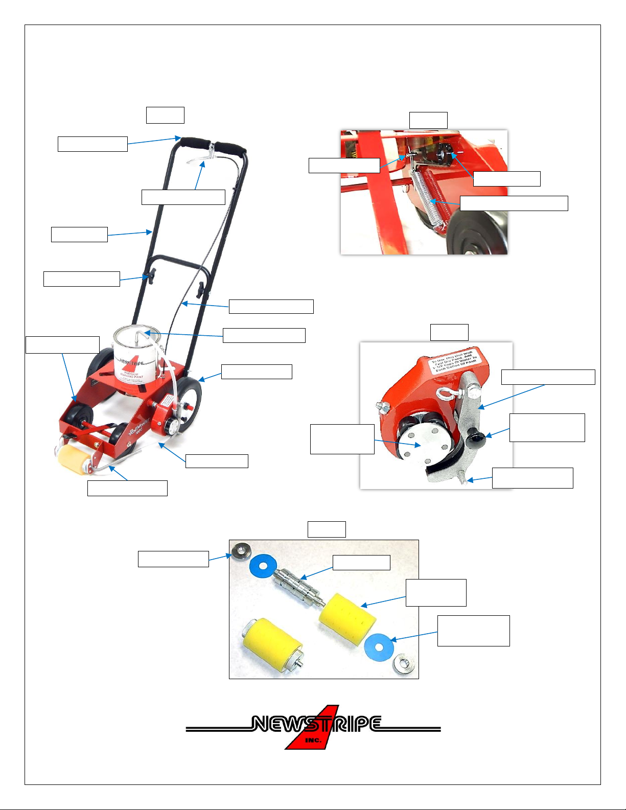
PARTS LIST
Item Number Description Part Number
1 Tube, Paint Can 10000665
2 Hose, Paint (5 pack) 10002496
3 Mandrel tube assembly 10003864
4 “O” ring 3/8” ID X 1/32” Thick 10000027
5 Knurled Nut (2 req’d) 10000646
6 Mandrel 10000643
7 Trough assembly 10000652
8 Trough Lock Pin Kit 10000671
9 Pump Rotor assembly 10000654
10 Tire, Pump Drive (not shown) 10000650
11 Cable, Control (Sheath cut to 35”) 10000820
12 Handle 10004852
13 Grip, Foam (2 req’d) 10000967
14 Lever, Control 10000821
15 Wheel, Front 10000753
16 Wheel, Rear 10003837
17 Punch, Can Hole 10000669
18 Spring, Actuating Arm 10000692
19 Cable Stop 10001577
20 Cable Adjuster 10000018
21 Roller Carrier with “J” Yokes 10004024
22 Replaceable “J” Yokes 10004023
23 Wing Nut (4 req’d) 10000107
24 Wing Knob (2 req’d) 10004899
25 Replaceable roller covers, regulating discs and paint hoses
3 pack Replacement Roller Kits include 3 roller covers, paint hoses & 12 discs:
4” Replacement Roller Kit 10004377
3” Replacement Roller Kit 10004378
2” Replacement Roller Kit 10004379
12 pack Replacement Rollers include 12 roller covers & 48 discs:
4” Replacement Rollers and discs 10000728
3” Replacement Rollers and discs 10001461
2” Replacement Rollers and discs 10000729
Optional Left Position Roller Kit 10004461
Includes: Mandrel Tube Assembly for left position (10003866), Left Position
Striping Bracket (10003865), 5/16-18 x 3/4” Bolts (2) (10001499),
5/16” Flat Washers (4) (10000095), 5/16-18 KEPS Nuts (2) (10004461)