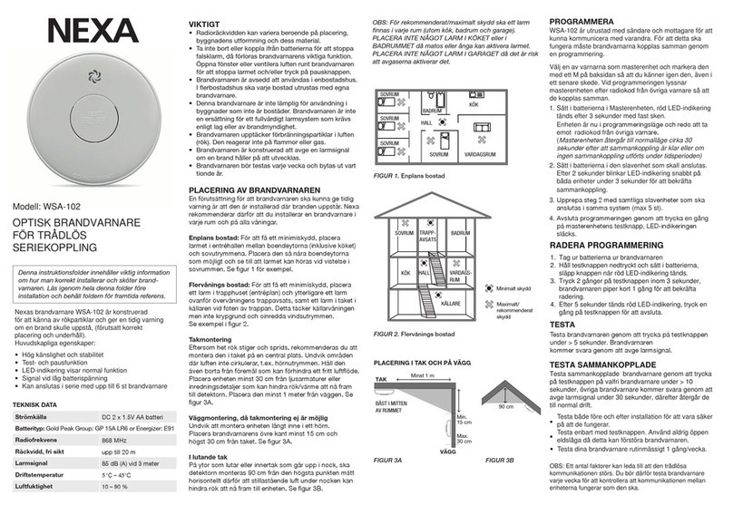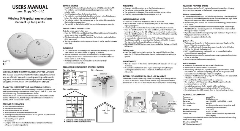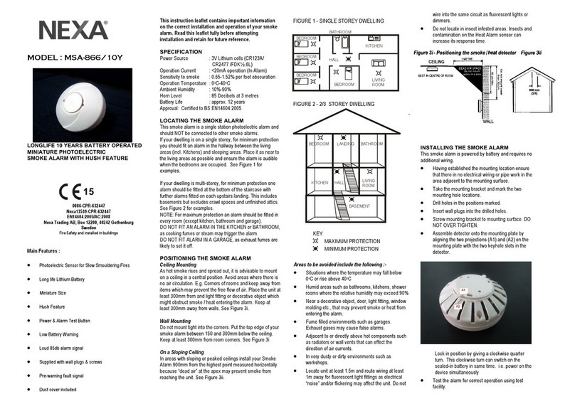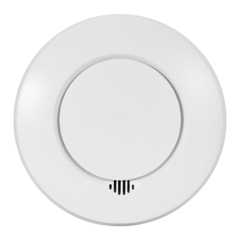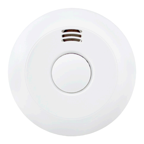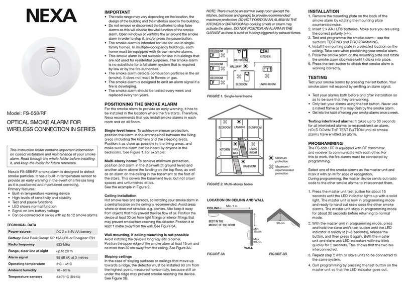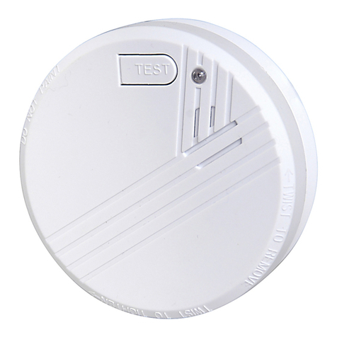
IMPORTA T!
The setting of the dip switch must be the same on
all interconnected units.
•
Connect the wires to the correct termina s on the
mounting base and fix the mounting base in position..
Ensure the screws are fu y tightened. See Figure 5.
Figure 6 – Wiring &
Interconnect faci ity
The alarm must be wired in accordance with
ational wiring codes.
LIVE : connect to house wires coloured Brown,
Red or marked with L.
EUTRAL : connect to house wires coloured
Blue, Black or marked with .
INTERCONNECT : norma y not used except to
hardwire interconnect to the mains smoke (Garvan
mode GNS-2236) or heat a arm (Garvan mode
GNS-1263S). Never use EARTH wire for
interconnect wire.
Remark
G S-2236RF smoke alarm & G S-2263RF heat alarm
are detectors, which can be interconnected with
each other by wireless radio links.
In another case, the user will have the option to
interconnect them to the other hard wired type
smoke alarms by the wiring be the “interconnection
terminal” on the base.
WAR I G: Connection to the EARTH terminal is not
needed for correct functioning of the Smoke Alarm. It is
just for conveniently terminating any earth supply wire
coloured green or green/yellow. It does not provide
protective earthing for the Smoke Alarm
•
Insert a 9V battery firm y into battery compartment on
the rear of the a arm. NOTE POLARITY OF
CONNECTIONS. Ensure the meta tab is fu y
depressed when the battery has been fitted.
NOTE – For the safety of the end user the smoke a arm
cannot be fitted without its battery.
•
Before assemb y to base p ate test the correct operation
of the smoke a arm (operating from the battery on y) by
depressing the test button on the front of the a arm. The
unit shou d emit a oud pu sating a arm.
•
Assemb e a arm onto the mounting p ate by s iding it in
according to the direction of the arrows.
•
Restore the AC supp y
•
Test the correct operation of the smoke a arm by
depressing the test button on the front of the detector. The
unit shou d emit a oud pu sating a arm.
•
Shou d use 2.1mm wire for connection.
OPERATING YOUR SMOKE ALARM
Once the smoke a arm has been insta ed a sma GREEN
indicator ight (LED) shou d be visib e through the a arm gri
indicating that AC supp y is hea thy. A RED indicator ight (LED)
shou d a so f ash approximate y once a minute to indicate the
battery is hea thy and the unit is operating proper y.
If smoke is detected, the unit wi emit a oad pu sating a arm and
a RED indicator ight (LED) wi be f ashing quick y at the same
time unti the air is c ear.
At norma time, the radio ink modu e is working under s eep
mode. It wi open the receiving window at a short time around
every 20 seconds. In order to awake it and set it at transmission
mode, the simp est way is to press the button on top of the
smoke detector. It wi continua y transmit as ong as the button
is pressed.
To ast two units’ transmission and reception performances’
parameters, it is important to set them with the same code. The
dip switch for setting the code is avai ab e on the mounting base
of the unit. When one is at its receiving mode, it can receive a
triggering signa from the transmitting unit within 20 seconds. As
soon as the receiving unit gets the signa , it wi activate the
a arm to sound oud y unit the transmitting signa is vanished.
TESTING YOUR SMOKE ALARM
It is recommended that you test your smoke a arm once a week
to ensure the detector is working correct y.
Push and ho d the test button for approximate y 3 seconds. A
oud pu sating a arm shou d sound and a RED indicator ight
(LED)wi f ash at the same time.
NOTE – for mu tip e interconnected smoke a arms(either by
radio ink or hardwire), on y the RED indicator ight (LED) of the
originating unit wi f ash rapid y. A other units in the
interconnect system wi sound an a arm(for radio ink
interconnected units, it wi sound within 20 seconds) but their
RED indicator ight (LED) wi NOT f ash. Test each a arm
checking that the a arm is triggered on a other a arms insta ed.
HUSH OR SILENCE FEATURE
This Smoke A arm has a bui t-in Hush or Si ence feature
incorporated into the Test button. If cooking or other non-
hazardous sources cause the unwanted a arm, it can be
temporari y si enced by depressing the test button and ho ding
for approximate y 3 seconds. The a arm wi enter a dormant
period for 10 minutes. The red LED wi f ash every 10 seconds
to indicate the sensitivity is reduced. At the end of the hush
period the a arm wi reset to norma sensitivity.
OTE – If the smoke density increase during this period(i.e.
from a fire) the unit wi go into a arm mode.
LOW BATTERY WARNING
If the smoke a arm emits a short ‘beep’ once a minute the
battery is at the end of its ife and shou d be rep aced
immediate y. This ow vo tage warning wi be given for at east
30 days. In this case, the other interconnected units in the
system which are not in ow battery condition wi chirps for a
few seconds once a hour as ong as the detector with the
“dead” battery beeps.
If the red indicator ight (LED) does not f ash every minute then
rep ace the battery.
BATTERY REPLACEMENT
A ways TURN OFF the A.C. supp y to the smoke a arm before
rep acing the battery. Rep ace the battery at east once
annua y, or immediate y when the ow battery signa sounds
once a minute, even though the smoke a arm is receiving A.C.
power.
Test the alarm for correct operation using the test facility
whenever the battery is replaced.
WAR I G: DA GER OF EXPLOSIO IF BATTERY IS
I CORRECTLY REPLACED. THE USE OF BATTERIES
OTHER THA THOSE RECOMME DED O THE BACK OF
THE SMOKE ALARM MAY BE DETRIME TAL TO ITS
OPERATIO
The battery shou d on y be rep aced by a qua ified e ectrician or
simi ar y qua ified person.
•
Turn off the A.C. power supp y to the smoke a arm.
•
Gent y s ide the smoke a arm out from the mounting
p ate.
•
Remove the battery from the compartment.
•
Insert a new, hea thy 9V battery. NOTE POLARITY OF
CONNECTIONS. Ensure the meta tab is fu y
depressed when the battery has been fitted
•
Using the Push-to-Test button, test the smoke a arm to
verify 9V DC battery back-up. See “TESTING YOUR
SMOKE ALARM”
•
Reattached the smoke a arm to the mounting p ate by
s iding unti it snaps into p ace.
•
Turn on the AC power and test the smoke a arm using
the Push-to-Test button. See “TESTING YOUR SMOKE
ALARM”
MAINTAINING YOUR SMOKE ALARM
C ean your smoke a arm at east once every six months to
prevent dust bui d up. This can be done using a vacuum
c eaner with the brush attachment. C ean gent y around the
front gri ed section and sides.
The apparatus shall not be exposed to dripping or
splashing and no objects filled with liquids, such as vases,
shall be placed on the apparatus.
IMPORTANT SAFEGUARDS
Insta ation of your smoke a arm is on y one step in your safety
p an. Other important steps shou d be taken to further improve
your safety:-
•
Insta the smoke a arm proper y, fo owing this
instruction eaf et
•
Test your smoke a arm week y
•
Rep ace the battery immediate y once dep eted
•
Do not smoke in bed
•
Keep matches & ighters away from chi dren
•
Store f ammab e materia s in a proper manner and never use
them near naked f ames or sparks
•
Maintain emergency equipment such as Fire Extinguishers,
escape adders etc and ensure a occupants know how to
use them correct y.
•
P an an escape route/s from your bui ding in advance and
ensure a occupants are aware of them. Re-enforce this
awareness periodica y through-out the year.
•
Make sure escape routes remain free of any obstructions.
WAR I G: IF THERE IS A Y QUESTIO AS TO THE CAUSE OF
A ALARM IT SHOULD BE ASSUMED THAT THE ALARM IS
DUE TO A ACTUAL FIRE A D THE DWELLI G SHOULD BE
EVACUATED IMMEDIATELY.
THIS PRODUCT IS A SEALED UNIT AND CANNOT BE
REPAIRED – IF THE UNIT IS TAMPERED WITH IT WILL
INVALIDATE THE GUARANTEE. IF THE UNIT IS FAULTY
PLEASE RETURN IT TO YOUR ORIGINAL SUPPLIER WITH
YOUR PROOF OF PURCHASE.
YOUR SMOKE ALARM GUARANTEE
These smoke a arms are guaranteed to be free from defects in
materia s and workmanships under norma use and service for a
period of three years from date of purchase. The company wi not
be ob igated to repair or rep ace parts which are found to be in need
of repair because of misuse, damage or a terations occur after the
date of purchase. Send the Smoke A arm with proof of purchase,
postage and return postage prepaid, to oca distributor. The iabi ity
of the company arising from the sa e of this smoke a arm sha not in
any case exceed the cost of rep acement of smoke a arm and in no
case sha the company be iab e for consequentia oss or damages
resu ting from the fai ure of the smoke a arm.
NEXA TRADING AB. SHALL HAVE NO LIABILITY FOR ANY
PERSONAL INJURY OR PROPERTY DAMAGE, OR ANY SPECIAL
INCIDENTAL, CONTINGENT OR CONSEQUENTIAL DAMAGE OF ANY
KIND RESULTING FROM A FIRE. THE EXCLUSIVE REMEDY FOR
BREACH OF THE LIMITED WARRANTY CONTAINED HEREIN IS THE
REPAIR OR REPLACEMENT OF THE DETECTIVE PRODUCT AT
NEXA TRADING AB. OPTION. IN NO CASE SHALL NEXA TRADING
AB’S LIABILITY UNDER ANY OTHER REMEDY PRESCRIBED BY LAW
EXCEED THE PURCHASE PRICE. YOUR SMOKE ALARMS IS NOT A
SUBSTITUTE FOR PROPERTY, DISABILITY, LIFE OR OTHER
INSURANCE OF ANY KIND. APPROPRIATE COVERAGE IS YOUR
RESPONSIBILITY. CONSULT YOUR INSURANCE AGENT.
This does not affect your statutory rights.
This a arm is on y suitab e for sing e occupancy private dwe ings
on y and not intended for mu ti occupancy private dwe ings or
commercia or industria dwe ings.
Waste e ectrica products shou d not be disposed of with norma
househo d waste. P ease recyc e where faci ities exist. Check with
your Loca Authority or retai er for recyc ing advice. New regu ation
wi encourage the recyc ing of Waste from E ectrica
and E ectronic
Equipment (European "WEEE Directive" effective August 2005).
Manufacturer: Garvan Enterprises Ltd.,
Hong Kong
Distributor:
exa Trading AB
Sweden
www.nexa.se
Ver: 25-Jun-2013
MNGNS2236RF02A1E
