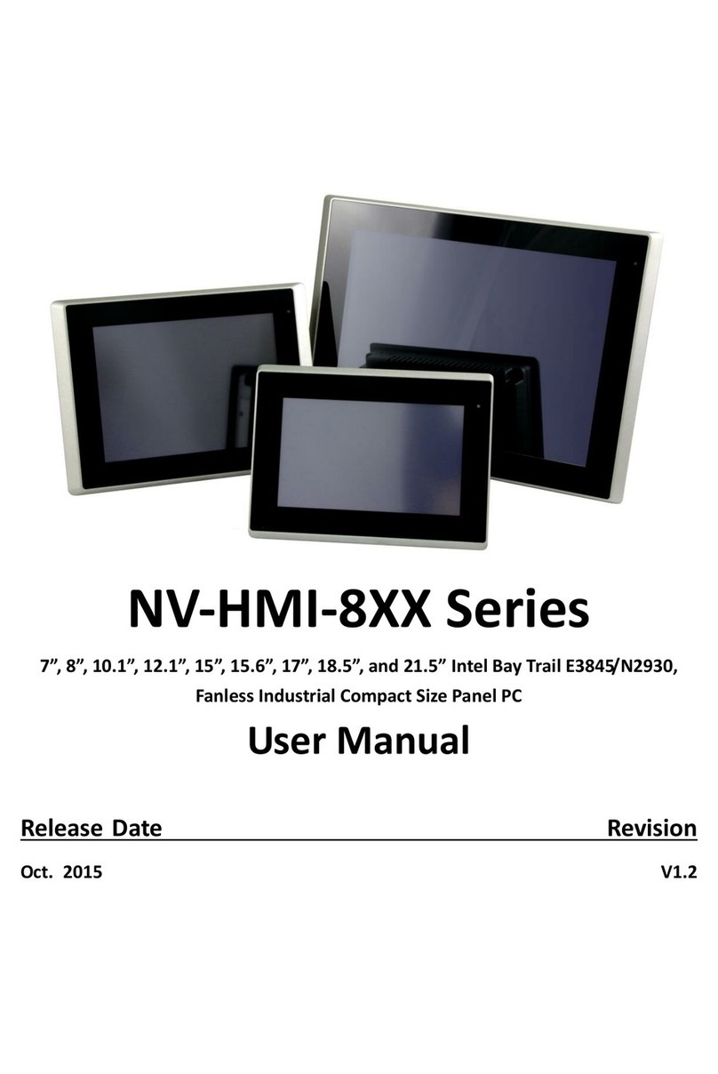
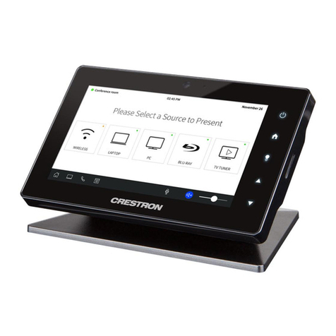
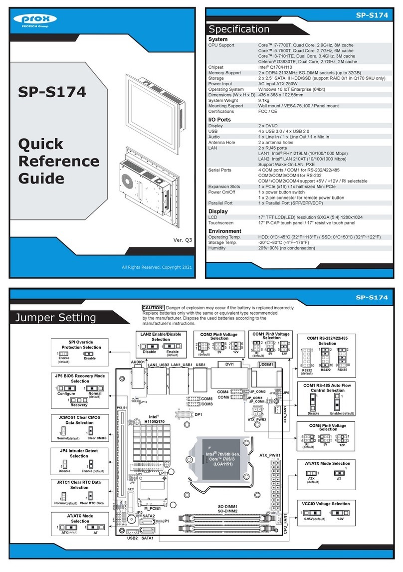
Next Wave CNC LCD Pendant User manual

LCD Pendant
© 2022 Next Wave CNC - All Rights Reserved

Next Wave CNC warrants your new Shark LCD Pendant to be free from defects in
material and workmanship for TWO YEARS from the date of purchase. The warranty
applies only to the original retail purchaser of the SHARK LCD Pendant when pur-
chased from an authorized Next Wave CNC distributor. This Warranty covers the parts
and labor to correct the defect. It does not cover the cost of shipping the machine and/
or parts to Next Wave CNC for evaluation or repair.
This warranty does not apply to problems arising from normal wear and tear, misuse, abuse, negli-
gence, accidents, unauthorized repairs, alterations, or lack of maintenance. This warranty is void if the
SHARK LCD Pendant or any portion of it is modified without prior written permission form Next Wave
CNC, or if the machine is located or has been outside the country where the machine was purchased.
Please contact Next Wave CNC to take advantage of this warranty. If Next Wave CNC determines that
your SHARK LCD Pendant is defective in material or workmanship, Next Wave CNC will at its ex-
pense and upon proof of purchase send replacement parts to the original retail purchaser necessary
to cure the defect. Next Wave CNC will repair the SHARK LCD Pendant provided it is returned to Next
Wave CNC, shipping prepaid, with proof or purchase and within warranty period.
Next Wave CNC disclaims all other express or implied warranties, including fitness for a particular
purpose. Next Wave CNC shall not be liable for death, injuries to persons or property, or incidental,
consequential, contingent or special damages arising from the use of the SHARK LCD Pendant.
All other trademarks are the property of their respective owners. Information in this manual is
subject to change without notice. The most recent version of this manual can be found at
www.NextWaveCNC.com/downloads-links
Copyright 2022 Next Wave CNC
All Rights Reserved.
SHARK is the registered trademark of
Next Wave CNC.
Ready2Control is copyrighted by
Next Wave CNC.
Virtual Zero Unlimited is patented by
Next Wave CNC.
Version: 07/04/2022
Watch Getting Started with your LCD Pendant training video at:
https://www.nextwavecnc.com/webinars

Warranty.................................................1
Technical Support.................................2
Pendant System Requirements.......................2
Pendant Overview.................................4
Pendant Registration............................5
Pendant Quick Guide............................6
Main Screen Function Keys ...............7
Homing Routine .........................................9
Touch Plate Routine .................................. 11
Axis Edit Screens...................................... 11
Pendant Workow............................... 13
Setup Menu .......................................... 18
Jog Speed.............................................. 18
Beep Sound............................................ 19
Model Number......................................... 19
Display Metric.......................................... 19
Safe Height.............................................20
Apps Menu ..........................................21
Touch Plate Callibration ..............................21
Virtual Zero.............................................22
Job Array ...............................................30
Home X- & Y- ..........................................31
Center Finder ..........................................31
Digitizer .................................................31
Laser....................................................31
Factrory Restore.......................................32
Unregistered Pendant ................................32
About Pendant.........................................32
About Controller .......................................32
Check Firmware.......................................32
Maintenance........................................33
Upgrade Accessories ........................34
CONTENTS
Next Wave CNC, LLC,
600 W. Boundary St., Perrysburg, Ohio 43551
USA
Main Office Phone (419) 318-4822
info@nextwaveCNC.com
®
Technical Support
If you need technical assistance with your
SHARK LCD Pendant, please visit our
Support webpage at:
NextWaveCNC.com/support
or email Customer Support at:
Support@NextWaveCNC.com.
Please include your product model number,
date of purchase, and other pertinent infor-
mation associated with the issue, such as
.tap files, VCarve files, screen captures, or
photos of your setup or the problem.
Support Email: support@NextWaveCNC.com
Available: 9am – 5pm Monday – Friday
(Eastern Time).
LCD Pendant System Requirements – The
LCD is compatible with all current SHARK
HD and SD series CNC machines as well as
past machines that use a control box with a
Pendant cable input port. Some (but not all)
older machines that lack the Pendant input
port can be upgraded by switching to the new
style Control Box that has the Pendant input
port. For information on upgrading an older
Next Wave CNC machine contact Customer
Service at Support@NextWaveCNC.com
2 3

Registering the Pendant
Click
Here
Unlock the Pendant by entering the access code
you received upon registration.
After successfully unlocking the Pendant, you’re
ready to control your SHARK HD CNC.
Pendant Registration
Before continuing the setup of your SHARK HD CNC,
register your machine online by navigating your web
browser to NextWaveCNC.com. Click on the PRODUCT
REGISTRATION tab at the top of the screen (see above).
Once you complete the registration, create a customer
account and follow the instructions to generate a unique
code to unlock your Pendant.You will also receive the
code in your email inbox. Use the number keys on the
Pendant to enter your Unlock (Access) Code. Press Sub-
mit. This unlocks the Pendant.
Your SHARK CNC is now unlocked, and ready to use.
Pendant Overview
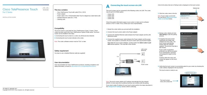
The Pendant serves as the primary interface that allows
you to operate and control your SHARK CNC. The touch
screen allows you to control the CNC using your finger, a
soft stylus, or a pencil eraser.
You will also find three connectors on the Pendant. The
multi-pin connector on the bottom of the Pendant fits the
cable from the CNC’s control box. Connect this cable
first. The optional Z touch plate accessory plugs into
the jack on the left side of the Pendant. The touch plate
zeros the Z-axis prior to cutting. The USB Type-A port on
the right side accepts a USB flash drive containing the
TAP/G-code files to cut your project on the CNC.
DO NOT plug in and turn on the control power until all the motor and
Pendant cables have been attached. DO NOT attach or remove the
motor or Pendant cables when the control box is powered up as this
can damage the electronics and is not covered by the warranty.
Warning
Z Touch Plate
Accessory Port
Left End
View of
Pendant
Right End
View of
Pendant
USB Port
Control box cable
connection
4 5
Serial Number and Software License Information:
For easy reference and record keeping, enter your
SHARK Pendant and Controller information below.
LCD Pendant Unlock Code
___________________________________
LCD Pendant Serial Number
___________________________________
Controller Box Serial Number
___________________________________

7
Quick Guide to Basic Pendant Function Keys
CNC Top View CNC Front View
Axis jog buttons – These six buttons control the
movement of the router in the specified direction. Use
them to jog the router to set a zero point, move it out of
the way while securing or removing material, or move it to
a convenient spot to change the bit. Change the speed of
the movement by toggling the jog speed button.
Axis position elds- These
three fields show the current X,
Y, and Z location of the router bit.
Keep in mind that the location is
always relative to where the zero
points of the X-, Y-, and Z-axes
have been set. Pressing on an Axis
position field button opens the Axis
edit screen for that axis (see page
13 for more information).
6
Slow, Med, and Fast Jog
speeds – press to toggle be-
tween jog speeds. You can use
the fast speed to quickly jog the
unit into a general position and
switch to med or slow for the
fine control needed for setting a
zero point.
Plate – The Plate button
allows you to use the op-
tional Z-axis touch plate, a
handy accessory for quick-
ly setting the zero point for
the Z- axis (see page 11).
Main Screen Function Keys
Home - The Home key uses sen-
sors located on the X- and Y- axes
to Home (zero) the machine. The
Home position serves as an origin
for setting up repeating operations
(see page 9).
Zero Z – Pressing this
key zeros out the Z-axis
at its current position.
The Z- position field will
reset to 000. Use this
function to manually set
the zero position of the
Z- axis.

8 9
Access the Home X & Y Axes function by pressing
the Home button on the Main screen (page 7) or on
the Apps screen (shown above).
Select Home X-axis to calibrate the zero point for
the X-axis home position.
2
1
Make sure the router bit is within 4” of the lower left
corner in the X- and Y-directions.
3
The Home X & Y Axes app calibrates and zeros out the X-
and Y- axes to the machine’s Home location in the front-left
corner of the table for Shark HD5 series machines and the
rear-left corner on a Shark SD120 machine.
NOTE: The SD100 and SD110 do not have the required sen-
sors, so the Home app does not apply to those machines.
X-Y Home can be calibrated each time you power up
your Shark or at any time before you run a project file.
Using the Home X- and Y-Axes provides a consistent,
repeatable reference point that is particularly useful when
using jigs, or when you need to run a cutting file from a
precise location.
To access the Homing function press the Home button
on the Main Screen (page 7) or open it from the Apps
menu (Figure 1). Select Home X-Axis from the list to set
its home location (Figure 2). Move the router bit to within
4” of the lower left side before proceeding and press OK
(Figure 3). The router will move to the X-axis Home (zero)
location (Figure 4) and display the value. Press OK to
accept the value (Figure 5) and repeat these steps for the
Y- axis.
The X- and Y-Offset options on the menu allow you to set
the X-Y zero location a precise distance from the ma-
chine’s Home position (Figures 7,8). This new location can
be referred to as “project zero.” It gives you the flexibil-
ity of using the X- and Y-datum point established when
creating a project in VCarve at a convenient location on
the machine. The combination of Homing and Offsets
provides absolute repeatability in job setups.
Press the Mv 0,0 button on the main screen to move the
router to the new “project zero” (Offset) location.
Home X & Y Axes App
Homing X & Y Axes
When the Homing routine completes, the Z-axis will be
centered over the machine’s Home location and the Pen-
dant X & Y Position elds will read 0.000 (Figure 5).
4
Zero XY– Press
this button to zero the
X- and Y-axes to the
current position of the
router. The X- and Y-
position fields will reset
to 0.000. Use this when
positioning the router
bit over the datum (XY
zero) point on a project.
Setup - Press Setup to
access the Setup sub-
menu. The Setup sub-
menu contains options
that control how the
Pendant functions (see
page 18).
Apps – Press Apps
to view the Apps
submenu. It contains
special functions for
calibrating the op-
eration of the CNC.
It’s also used with
optional accessories
(see page 22).
Mv 0,0 – This button automatically jogs the router in one
of two ways, depending on how you press the button.
A single tap jogs the router to the X- and Y- axes zero
position.
A quick double tap moves the router to the X-, Y- and Z-
axes zero position.
The Mv 0,0 key is handy for quickly moving the router
back into position to start a cut. In addition, if you are in
the process of cutting many parts but need to shut your
machine down at the end of the day you can bring the
router back to the 0,0,0 point. The next time you start
your machine the axes will already be zeroed out to that
location and you are ready to pick up where you left off.
Axis Edit Screen Access - press the the
Axis Position button to open the corresponding
Axis Edit Screen (see page 13)
USB – Press this button
to select a cutting (.tap)
file you transferred from
your computer to the USB
drive (see page 15).

10
Press OK to accept the X-axis location. Repeat the
process to calibrate the Y-axis.
Press Home on the main screen to set the X and Y
offset distances from the Home position.
7
5
Home X & Y Axes continued
The Speed function allows you to set the speed the
router moves to the Home position.
9
The router carriage will begin to move in the X
direction until it contacts the limit switch.
The X and Y Position elds should read 0.000 after
calibration.
6
4
Enter a value to set the offset distance of the X-axis
from 0,0. Repeat the process to set the Y Offset.
8
11
The optional Shark Z Zero Touch Plate accessory (see
page 35) provides a fast and accurate way to zero the Z-
axis. It’s a useful upgrade for your Shark CNC router that
makes this process easier. Simply place the touch plate
on top of the material to be routed before completing the
process.
The touch plate assembly includes a 33⁄88”-thick aluminum
disc and a cable assembly. One end of the cable is fitted
with an 11⁄88” plug that fits into the jack on the side of the
Pendant. The opposite end of the coiled cable features
two leads: an aluminum touch plate, and the other lead
has a small magnet that you attach to the router bit.
This completes the circuit when the bit touches the plate
during the zeroing process.
Shark Z Zero Touch Plate
Touch Plate App
Press the APPS button on the Main screen to ac-
cess the option to calibrate the touch plate.
The Run Z Calibration option begins the routine to
zero the Z- axis using the touch plate.
Raise the touch plate until it touches the router bit to
conrm a proper connection.
Make sure the magnet is attached to the router bit
before pressing OK.
34
12
There are two ways to access the Touch Plate Calibra-
tion option: press the Plate key on the Main Screen or
press Apps to display a list of options (Figure 1), includ-
ing Touch Plate Calibration. Select this option, then Press
to Open to display three choices. Run Z Calibration per-
forms the operation to zero the Z- axis, a Speed option
sets the plunge rate of the Z- axis during calibration, and
Plate Thickness stores the thickness of the touch plate .
The default values for these work well for most applica-
tions. Select Run Z Calibration (Figure 2).
As instructed in Figure 3, Press OK to verify the touch
plate is connected properly.

12
Raise the touch plate to touch the router bit (Figure 4).
While the plate is touching the bit, you should see a red
screen as shown in Figure 5. Replace the touch plate
below the bit and press OK to begin the movement of the
router in the Z- axis (Figure 6).
Z Zero Touch Plate continued
Zeroing X- and Y- Axes
Holding the touch plate against the router bit con-
rms that you can proceed to the next step.
Move the touch plate under the bit and press OK to
begin router movement.
The calculated Z value is displayed. Press OK to
accept these results.
The bit lowers until it contacts the touch plate then
raises to allow removal of the plate and cables.
78
56
The bit will move downward until it contacts the touch
plate (Figure 7) and immediately raise to a safe height.
On the next screen (Figure 8), press OK, then remove
the touch plate and magnet.
Axis Edit Screens
13
a
lj
b
c
k
i
h
g
f
e
a
b
Edit X & Y Axes
Editing the Z-axis uses the same functions as above
except that the Active Axis and View A buttons are also
relevant to the A-axis (see next page).
a. Active Axis: This value, shown in the upper left corner,
toggles between Z- and A-axis with the use of the View
A or View Z button.
b. View A: Press to toggle the Edit Screen and the Main
Control Screen to the A-axis view.
Edit Z Axis
d
On the main screen of the Pendant, pressing the Position
field for the X-, Y-, or Z-axis at the top of the screen allows
you to make adjustments to the selected axis.You can also
calculate values using the numeric and math function keys.
a. Active Axis: Displays the axis that is currently open for
editing.
b. Mv to 0: Moves the axis to its current zero position.
c. Set: Sets the new location entered in the Position field.
This also changes the value on the Main Screen.
d. View Z: Toggles the Edit Screen and Main Control
Screen between the Z and A (see below).
e. +/- button: Toggles the position field between a posi-
tive and negative value.
f. Function keys: Similar to those on a typical math cal-
culator.
g. Move: Press to move the axis to the location currently
showing in the position field.
h. Location: Press to recall the current axis location.
i. C: Clears (deletes) the information in the position field.
j. Exit screen: Press the X symbol to exit the edit screen
and return to the main control screen.
k. Position field: Displays the current or edited position
of the axis. Use the keypad to edit this field.
l. Number keypad: Enters a new location in the position
field. Can also be used for calculations.

1
Routing projects with your Shark CNC consists of a few
basic steps, a summary of these steps is listed below and
detailed on the following pages:
1. Save toolpaths from the VCarve design file to a USB
flash drive.
2. Insert the flash drive into the Pendant.
3. Mount the project material to the bed of the CNC.
4 Install a router bit.
5. Zero the X- and Y-axes.
6. Zero the Z-axis.
7. Press the USB button on the Pendant to access the
toolpath file.
8. Select the toolpath file.
9. Verify the setup parameters shown on the Pendant
screen.
10. Press Start to begin routing your project.
1. SAVE TOOLPATH FILES. After completing the project
design and generating the toolpaths in VCarve, save the
toolpaths to a USB flash drive so you can load the files
into the Pendant. To do this, select the toolpaths you wish
to save then select the Post Processor that matches your
machine. For the Shark CNC router select the Next Wave
CNC (*.tap) post processor (Figure 1). The post proces-
sor converts the VCarve toolpath selections into instruc-
tions for the CNC to rout the project. The code file has
a .tap extension and is commonly referred to as a “tap,”
“G-code,” or “cutting file.” Finish by pressing the Save
Toolpath button and saving the file to a USB flash drive
(Figure 1).
2. INSERT USB DRIVE. To enable the Pendant to load
the toolpath (.tap) file, switch on the control box and
insert the USB drive into the USB port on the side of the
Pendant. You’ll select the required toolpath file later.
Pendant WorkowA-Axis Edit Screen
14
a
b
c
a. Active Axis: This value, shown in the upper left corner,
toggles between Z- and A-axis with the use of the View
A or View Z button.
b. View Z: Press to toggle the Edit Screen and the Main
Control Screen to the Z-axis view.
c. Position field: Displays degrees of rotation.
d. A-axis controls: Use the numeric keypad to set the A-
axis degrees of rotation. The value also appears in the
Main Control Screen.
Edit A-Axis
d
2
15

7. PRESS THE USB BUTTON. With a USB drive insert-
ed into the Pendant, the USB button on the main screen
should turn blue. Press the USB button (Figure 7) to open
the file selection menu.
8. SELECT THE PROJECT FILE. From the displayed list,
select the project .tap file you want to cut (Figure 8).
9. VERIFY JOB SETUP. The next screen (Figure 9)
shows the parameters for the job including the CNC
name, material size, location of the Z origin, and the
location of the XY origin. Preview the settings to make
sure you’ve selected the correct .tap file. Also make sure
the settings match your VCarve file and CNC machine. If
everything checks out, press the Next button.
10. PRESS START! Review the safety check lists in your
CNC manual, then press the Start button (Figure 10).
Your Shark CNC will automatically turn on the router and
begin cutting the project.
If your project has more than one toolpath file, repeat
steps 4 through 10 for the remaining toolpath (.tap) files
for the project. When all of the .tap files have been run,
remove the project, sand off the rough edges, and apply
a finish.
Verify all of the set-up information for this job, review
the safety checklist, then press the Next button.
9
To begin the CNC operation, press the Start button.
If needed, the Stop button shuts down the CNC.
10
Review, Then Cut
After inserting the ash drive into the Pendant,
press the “USB” button to select the project le.
7
From the list of available projects, choose the ap-
propriate .tap le you wish to use.
8
17
16
CNC Setup
Insert the bit so that a small amount of smooth shank
shows between the collet and the cutting edges, but
also make sure the bit isn’t bottomed out in the collet.
Zero the Z axis by lowering the bit until it just
touches a piece of paper on the workpiece.
5
6
3. MOUNT THE WORKPIECE. To set up the origin of the
X-, Y-, and Z-axis on your workpiece, first mark the XY
datum (zero) position on your material. (Figure 3). The
marked datum point should match the location on the
workpiece you used in your VCarve design file. In our
example, the XY datum point is specified as the center of
the material.
Securely clamp the workpiece to the bed of the CNC
(Figure 3). Use enough clamps to ensure the workpiece
won’t shift during the routing process. It’s also important
to position the clamps so they're not in the way of the
toolpaths to be routed into the workpiece. A little careful
planning here will go a long way toward ensuring success
with your project.
4. INSTALL THE ROUTER BIT. Once the workpiece is
secured, properly install the router bit you specified in
VCarve for the toolpath you’ll be using (Figure 4).
5. ZERO THE X- AND Y-AXES. You’ll find an overview of
the main Pendant screen on pages 6-8. Use the four X
and Y buttons (Right X+, Left X-, Away Y+, Near Y-) of the
Pendant to jog the router close to the XY datum mark.
Notice the values in the Position boxes at the top of the
screen change values as you jog the router. Change the
jog speed to Slow and position the router bit directly over
the datum mark (Figure 5). Press the “Zero XY” button to
zero the X- and Y-axes. The values for the X- and Y-axes
should read 0.000 in the position boxes.
6. ZERO THE Z-AXIS. To zero the Z-axis, lower the bit
to within ½” of the top of the workpiece and set the jog
speed to Slow. Slide a piece of paper underneath the bit
and move it back and forth as you tap the “Dn Z-” button
to gradually lower the bit (Figure 6). When the bit “grabs”
the paper, stop. Press the “Zero Z” button. The Position
value for the Z-axis should read 0.000. Now, all three
axes are calibrated.
Raise the router bit approximately ½” to prepare for cut-
ting the project.
NOTE: A fast, easy, and accurate way to zero the Z-axis
is with the optional Z Zero Touch Plate accessory. See
page 11 and learn more at NextWaveCNC.com.
Zero the X and Y axis rst by jogging the bit until
it’s positioned over the center of the workpiece.
3
Collet Shank
4

Setup Menu
18 19
Setup Menu Screen: Press the Setup button on the Main Control screen to open
the Setup screen. The Setup menu contains options for controlling specic Pendant
functions. Press a menu item to open the settings screen for that option. To return to
the Main Control Screen, press X in the upper right corner.
Jog Speed: Press Jog Speed Fast, Medium, or
Slow to display the jog speed settings window. The
current jog speed appears in the top right of the
screen. Tapping this eld opens a numeric keypad
for entering a new value for the Jog Speed. Press
OK to save the setting.
LCD Brightness: Press the number eld in the
upper right to display the numeric keypad. Use the
keypad to adjust the brightness from 1 (dimmest) to
8 (brightest).
Beep Sound: Change the volume of the beeps
by selecting Beep Sound 0-4. Enter a value of 0
(silent) to 4 (loudest) using the keypad.
Model Number: This function controls several
settings on your Shark CNC such as motor rotation
and XY machine orientation. Verify the model num-
ber for your machine using the chart at right. Verify
this setting after performing a rmware update for
the Control Box or Pendant.
Machine Type Model Number
SD100/Barracuda 300
SD110 102
SD120 202
HD500, HD510, HD520 4003
Shark II, HD4, HD4 Ext. 4004
COMMON CONTROLS
- Press number field in the upper right to open the numeric keypad
- Use the keypad to enter a new setting
- Press OK on the keypad to save your setting
- Press the X in the upper right to exit Setup and return to the Main Screen.

20
Display Metric: Toggles between millimeter and
inch values displayed in the position fields on
the main screen. Enter either 1 for metric or 0 for
inches.
Safe Height: The Safe Z Height setting controls
how far the router bit rises above the Z zero
position when you press the Mv0,0 button on the
Main screen. This function helps prevent router bit
collisions and possible breakage with hold-down
clamps or other hardware. You can adjust the Safe
Height by pressing the Setup key on the Main
Screen. Scroll down the list to “Safe Height” (Fig-
ure 1). Adjust the Safe Height by pressing the nu-
merical field at the upper right of the screen. This
opens the numerical keypad. Enter the desired
value and press OK. Now when you press Mv 0,0
on the Main Screen, the router will move up to this
Safe Height and then to the X,Y zero location.
NOTE: To set the safe Z clearance during cutting
you need to adjust the Rapid Z Height in your
VCarve file.You access the Rapid Z Height setting
through the Material Setup button located at the
top of the Toolpath panel in VCarve or Aspire.
Apps Menu
Apps Menu Screen: The Apps submenu contains special functions for calibrating
and operating your Shark CNC and optional accessories. Select an item from the list
of apps and press Make Selection to open the settings screen for that option. Press X
to return to the Main Screen.
Touch Plate Calibration: Select this option then
Press To Open to initiate a series of steps that
quickly and accurately zeros out the Z-axis using
the Z Zero Touch Plate accessory (see page 11)
available from Next Wave CNC.
Virtual Zero: Select this app to adjust the .tap
cutting le to conform to a slightly warped, curved,
or uneven project material or machine table (see
next page).
21

23
Virtual Zero App
1
2
The Virtual Zero app makes adjustments
for project material that may not be flat.
This app allows you to define five Z zero
locations to account for the uneven materi-
al: each corner and the center. It maps the
uneven surface of the material and makes
adjustments to the Z-height values in the
.tap file.
The Virtual Zero profile automatically makes
the adjustments to every toolpath for the cut
file when different router bits are needed to
complete the project. The Virtual Zero map
remains in the Pendant memory until you
reset it or turn off the control box.
Mapping the surface of your material with
Virtual Zero requires a number of steps, so, take some
time to read through the steps and practice with your
machine before setting up to cut your project.
Create your project design as you normally would.
To prepare the design to use the Virtual Zero function, set the
Z Zero Position to the Material Surface and the XY Datum
Position to the center of your project.
Setting Up Virtual Zero
45
67
3
Create and
Save the project
toolpaths to a USB
thumb drive. In
this example of the
Virtual Zero logo,
two toolpaths are
saved: one for
carving the letter
using a 90° V-bit
and another tool-
path to cut the circle
using a straight bit.
After inserting USB device, use the Apps key and select the
Virtual Zero app. In the upper right of the screen touch Press
to Open to display the Virtual Zero settings screen.
Press the eld in the upper right of the screen to choose either
the probe or touch plate using the numeric keypad. Enter 0 to
use the probe or 1 to use the touch plate.
The Speed setting controls the Z-axis plunge rate. The default
setting of 10 works well for most situations. Change it by
pressing the settings eld in the upper right and enter a new
value using the numeric keypad.
The Touch Source denes the method used to set the Z zero
point. Many Shark CNC users will use the Shark Z Zero
Touch Plate. You may also use the optional digital probe
accessory.
22

25
Setting Up Virtual Zero continued
8
9
12
Diagram
Width
Length
Workpiece
10
11
The scan area denes where on the material you will be
setting the ve Z zero points. You can set this to any size,
but it’s usually best to limit it to the approximate size of the
cutting area. You can also set points that best represent the
area that will be carved. Another option is to bypass this step
and use the File Species width and length derived from the
VCarve cutting le.
Repeat the process for the “Scan Length Y” option.
Enable Virtual Zero pressing the settings eld in the upper
right and entering 1 for Yes. Press X to exit this screen and
return to the Main Screen.
After choosing “Scan Width X,” enter the width in the upper
right hand eld using the numeric keypoad, then press OK to
continue.
Enter the value for the Scan Length Y, then press OK to
continue.
Setting Up Virtual Zero continued
15 16
13
14
Use the Plate function and Z Zero Touch Plate to zero the Z-
axis to the top of the material.
Press the USB button to bring up the list of .tap les. Select
the toolpath le that you want to cut. In this example we are
starting with VZ Logo 01 VCarve.tap.
Review the header information screen. If everything looks OK,
press the Next button to continue.
Mark a center point on the workpiece. Install the appropriate
router bit. Move the router bit to the center mark. Press Zero
XY to zero the X- and Y-axes to the center of the material.
24

27
Setting Up Virtual Zero continued
17
18 19
20 21
On this screen, you’re presented with two options. The rst,
File Species, displays the material size you set up in VCarve
less 1”. This provides half of an inch clearance around the
material to assure the scan area stays within the boundary of
the material, and to allow some room for clamps.
The second option, Current Region, uses the scan area
specied in of the Virtual Zero app. See steps 8 through 10 on
page 24.
Both of these options take you to the next steps of capturing
the ve Z Zero capture points.
To dene new Virtual Zero coordinates, press Capture New
Points. Virtual Zero uses the Z Zero Touch Plate routine to
capture the scanned points. Virtual Zero will go through the Z
Zero Touch plate routine ve times in order to capture the four
corners and the center point of the area chosen to scan.
With the Z Zero Touch Plate connected to the Pendant, and its
magnet attached to the router bit, press OK.
Conrm a proper connection between the plate and Pendant
by touching the plate to the router bit.
When you touch the plate to the router bit, the red conrma-
tion screen appears.
Setting Up Virtual Zero continued
22 23
24 25
26 27
The Virtual Zero app records and shows how much each point
varies from the original Z zero position. After scanning a point
you can choose Redo Point or press OK to continue mapping.
A small green V appears in the top right corner of the screen
to signify that the le is using Virtual Zero. Press Start to begin
carving.
Ensure the touch plate is positioned below the router bit
before continuing. Press OK to conrm that you’re ready
to capture Virtual Zero points. These are typically the four
corners and center of the scan area dened earlier.
The router will move in the Z direction until it contacts the
touch plate. Repeat the process to dene all ve points.
When the ve Virtual Zero points are captured, the screen
shows the X and Y values of the scan area and how much
each capture point varies from the Z Zero height. Press Next
to begin carving your project.
As the project le is being processed, the Lines Sent, Trans-
mitted, and Time values are updated. After the rst le is done
running, press X to return to the main screen.
26

29
Setting Up Virtual Zero continued
28
30 31
32 33
29
Since you have already captured the ve Virtual Zero points
for this project, press the Existing Points button on the screen.
Use the same option for the Scan Region as you selected for
the rst toolpath above (Figure 13).
With a new router bit installed, you will need to recalibrate the
bit's Z zero with the touch plate once again.
Ensure the touch plate is positioned directly below the router
bit and select OK.
Press the USB button to bring up the list of .tap les. Select
the next toolpath le for the project. Install the appropriate
router bit for this toolpath.
Verify the project information and press Next to continue.
Setting Up Virtual Zero continued
34 35
36 37
38 39
Press Start to begin processing the le. The Virtual Zero
map can be used as many times as needed for your project.
Remember that the mapping is specic to a particular piece of
material, so if you install a new piece of material the mapping
must be redone.
As before, lift the plate to touch the router bit. This screen conrms the touch plate is connected properly.
Place the touch plate below the router bit and select OK. Allow the router to move down until it touches the plate.
Conrm the value by selecting OK. Remove the touch plate
and magnet before proceeding.
28

Setting Up Job Array
Job Array App
12
31
3 4
The Job Array app allows you to create
multiple parts from a single file set up.
This gives you flexibility and convenience
in setting up projects based on the size of
the material or how many parts need to be
made. With Job Array there is no need to
create a new file in VCarve for each part to
be cut.
After enabling Job Array (see below), you’ll
be able to select the cut file for which mul-
tiples are to be made.You can specify the
how the multiple parts are to be laid out and
cut based on the size of the material.
Open the Job Array app and select Enable Job Array from the
list. Press the entry box on the upper right to display a numer-
ic keyboard. Press 0 for Off or 1 to enable Job Array.
The X and Y Offsets sets the distance between the XY datum
points for each copy of the part dened in the design le.
Enter the distance in the upper right eld using the keypad.
Press # of Runs per Row to set the number of copies of the
project in the X direction using the numeric keypad.
Use the # of Rows function to set how many rows of the proj-
ect are in the Y direction using the numeric keypad.
30
Center Finder: This function is used by some older
machines but is not a function that applies to newer
machines and can be disregarded.
Laser: Use this app with the laser accessory to cre-
ate detailed laser-engraved photographic engrav-
ings, images, and lettering. See the Laser Owner’s
Manual for complete use and operating instructions.
Home X & Y Axes: This app calibrates and zeroes
out the X- and Y-axes to the machine’s home loca-
tion in the lower left corner of the table (page 15).
Digitizer: Use this app to map the shape of your
project using the Digital Duplicator accessory. You
can create a copy of an existing carving or use the
scan data with the Virtual Zero app. See the Digitiz-
er Owner’s Manual for complete use and operating
information.
4th Axis: This app provides setup options for the
various rotary 4th axis accessories available from
Next Wave CNC. See the 4th Axis Owner’s Manual
for complete use and operating instructions)
Factory Restore: Use this app to restore the de-
fault settings in the Setting and App screens.

33
About Pendant: Use this to display the Pendant
serial number and rmware information. This is
useful to verify rmware versions or when commu-
nicating with technical support personnel.
Check Firmware: This app runs a quick check and
displays a status report on your rmware. Firmware
updates are available at NextWaveCNC.com.
Unregister LCD: This option removes the access
code from the Pendant.
About Controller: This displays the controller (con-
trol box) serial number and rmware information.
Wipe the Pendant screen with a soft cloth and remove
sawdust buildup between the case and screen with a folded
piece of paper.
32
Maintenance
The Pendant is a durable and trouble-free tool for controlling
your Shark CNC, but the dust created by the router can
sometimes cause problems.
To keep the Pendant operating trouble-free, it’s important
to keep it clean. To clean the Pendant case and screen,
use canned air to blow off dust. Sometimes larger pieces of
sawdust can lodge between the LCD screen and the plastic
housing. To remove these bits of sawdust, fold a small piece
of paper and run it around the perimeter of the screen as
shown.
TIP - To reduce problems from dust, mount the pen-
dant on a stand or, if your CNC has an enclosure to
contain dust and noise, mount the Pendant on the
side of the enclosure. The bottom of the Pendant case fea-
tures a
11⁄44
”-20 thread you can use to mount the Pendant.
Sometimes it is necessary to recalibrate the Pendant screen
so that the keys are responsive and work properly. To do
this, first turn off the controller. Next, hold your finger on the
screen and restart the controller. This activates a series of
steps that step you through the process of recalibrating the
Pendant LCD screen.
Firmware updates are available at
NextWaveCNC.com/firmware
Find more maintenance and setup tips and
answers at:
https://www.nextwavecnc.com/
frequentlyaskedquestions

Upgrade Accessories
3HP WATER COOLED SPINDLE SYSTEM
SKU 20160
•Powerful 3HP motor
•Digital Speed Control
•ER20 collet system includes 1/4” & 1/2” collets
•Enclosed Cooling System
•In line Flow Indicator
•Powerful 2HP motor
•ER11 collet system includes 1/4” & 1/8” collets
•Water pump, hose and connection kit included
•110V uses standard 20 amp circuit
•6,000—24,000 rpm (rotations per minute) variable speed Inverter
•Spindle clamp adapts to existing router mounts
•Less than .005 mm runout Superior quiet operation Outer dimensions
80 mm x 180 mm
2HP WATER COOLED SPINDLE SYSTEM
SKU 20157
35
Upgrade Accessories continued
•Compatible with all Next Wave CNC machines.
•Required for using Virtual Zero Unlimited available on select machines
•Solid Aluminum Construction
•4 ft Cord (6’ extension cable also available)
•Sets Z axis at exact zero for precision cutting
•Lays flat on the material surface or machine bed
TOUCH PLATE
SKU 20141
•Use the 1” diameter mini touch plate in tight spots, especially
useful for Virtual Zero Unlimited
•Solid Aluminum Construction
•12” patch cord with banana receiver
•Requires standard NWCNC touch plate to work (SKU 20141)
MINI-TOUCH PLATE
SKU 20146
34

LCD PENDANT
User's Manual
Version: 07/04/2022
Table of contents
