NextDent LC-3DPRINT BOX User manual
Page 1 of 10
Instruction For Use
Leading manufacturer of dental materials for 3D printing
LC-3DPRINT BOX
Light Polymerisation unit (Post-curing oven)
LC-3DPrint Box
The following instruction is for professionals
who want to use the NextDentTM LC-3DPrint
Box as a light polymerisation unit (post-curing
oven)
LC-3DPrint Box is used to dry and polymerize 3D printing objects
which need an additional drying and polymerising process. This unit
is equipped with 12 pcs of 18W lights in order to dry and fully polym-
erize the 3D printed objects.

Page 2 of 10

Page 3 of 10
STOP: READ ME FIRST. DO
THIS AT INSTALLATION.
Check And Change Your Voltage If
Needed
The LC-3D Print Box comes with a pre-set voltage from
the factory that may require changing to align with
your country specic voltage rating.
Note: No damage will occur to your unit if
plugged into a different voltage than how
the unit is congured.
For proper heater and light output, it is required to
select the correct voltage. This is a one-time setting
done at initial setup of your LC-3D Print Box.
Follow these instructions on how to change the pre-
set voltage to your country specic voltage. Please
see the Voltage Chart below to identify your country
specic voltage.
Note: If your country is not listed, choose
the correct voltage from the pulldown list
on the print box (see voltage list below).
Country Voltage
Australia 230V
New
Zealand
230V
S. Korea 220V
Canada 120V
China 220V
Mexico 120V /
127V
Chile 220V
Turkey 220V /
230V
Portugal 230V
Morocco 220V /
127V
India 230V
Country Voltage
US 120V
Germany 230V
Italy 230V
Spain 230V
UK 230V
Ukraine 230V
France 230V
UAE 220V /
230V
Taiwan 110V
Russia 220V /
230V
Czech
Republic
230V
Voltage Selection
on Print Box
100V
110V/115V
120V/127V
220V
230V
240V
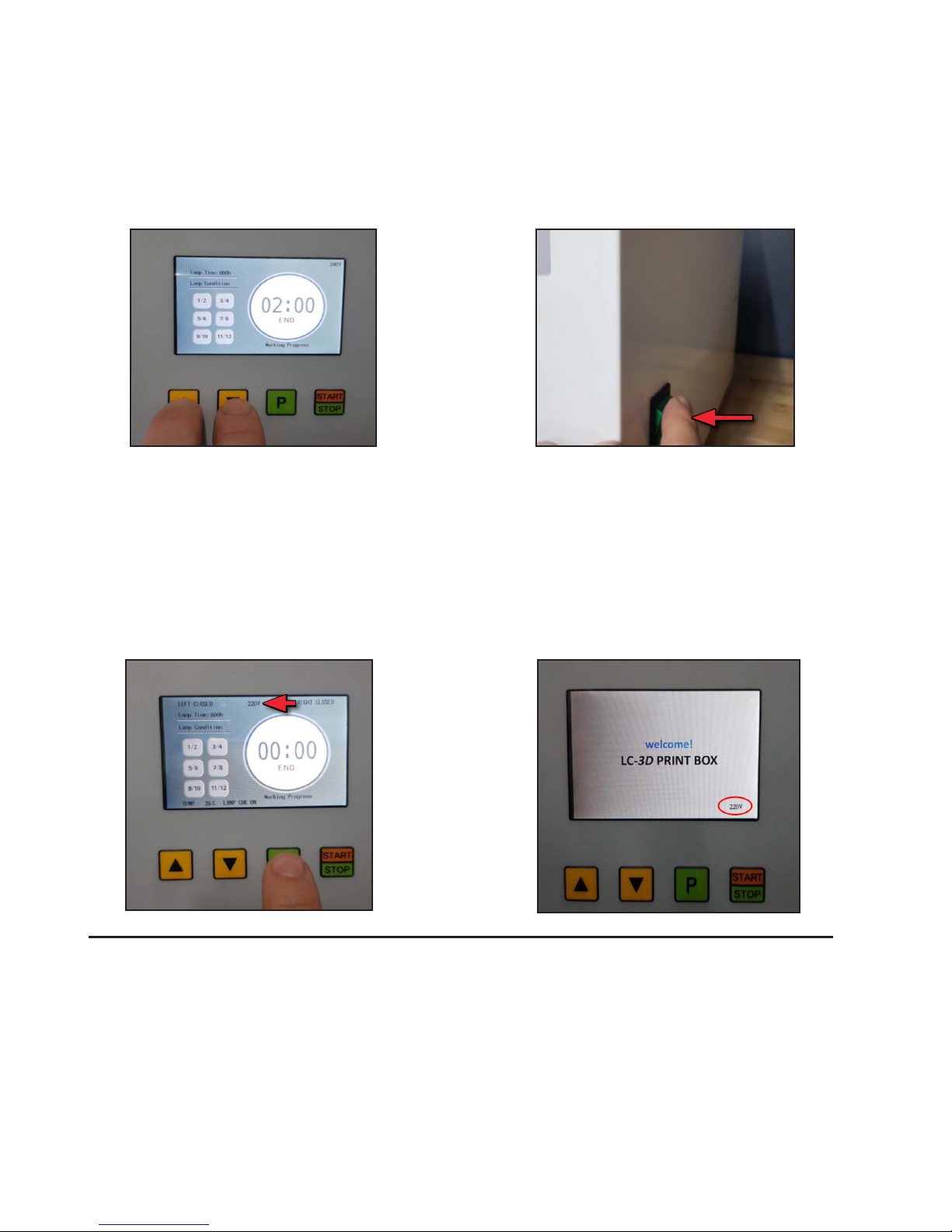
After print box is turned on, the pre-set voltage
appears at lower right corner of welcome screen. It
will also display on the main screen in the upper right
corner.
Page 4 of 10
1. Access the engineering mode display screen
by pressing the Arrow “Up” and “Down” button
together and hold for 3~4 seconds.
If the voltage needs to be changed, Please follow these steps to adjust the voltage setting.
2. In engineering mode (voltage appears in the top,
middle of screen), change voltage by pressing
the ‘P’ button. Please wait until you see that the
voltage has changed. Continue to press the “P”
button until your country specic voltage rating
appears.
3. To save the voltage, turn off the LC-3D Print box
using the power switch on right side of the print
box.
4. Once saved, the newly set voltage should
appear on the Welcome screen when the unit
is turned back on. This particular unit has been
changed to 220V.
Type of unit:
Model name:
Rated Voltage:
Power Consump-
tion:
Fuse:
Dimension:
Weight:
Light Polymerisation unit
(Post-curing oven)
LC-3DPrint Box
AC110-240V 50/60Hz
Max. 264W
AC250V T5.0A
W410 x D440 X H380
22Kg
Specications
Page 5 of 10
General cautions
-Read this manual before use.
-This machine should be used by professionals only.
-The built-in safety mechanism should not be re-
moved or modied.
-Do not allow unauthorized persons to repair the
machine.
-Do not use this machine for any other kind of mate-
rial than NextDentTM 3D printing Materials.
Package content
-NextDentTM LC-3DPrint Box
AC Power cable (250V,10/16A)
6 pcs of UV18W lamps-71 colour
6 pcs of UV18W lamps-78 colour
Metal plate with glass insert
Instruction for use
Electric diagram
Declaration of conformity
Warranty conditions
-
-
-
-
-
-
-
-
Transportation / preparing the
site of machine
-For units weighing more than 18kg (units weight:
22kg), transportation unit like a pallet truck is
needed and at least two persons are needed for
transportation and installation.
The surface should be at and free of dust.
Make sure there is enough space on all sides.
Make sure that there is enough space between fan
and wall.
This unit is for indoor use only.
-
-
-
-
Environmental conditions
-Temperature and Humidity: 5~40°C / 80%
Indoor use only-
Steps for installation
-Please read instructions for use .
Specically read general caution including safety
information.
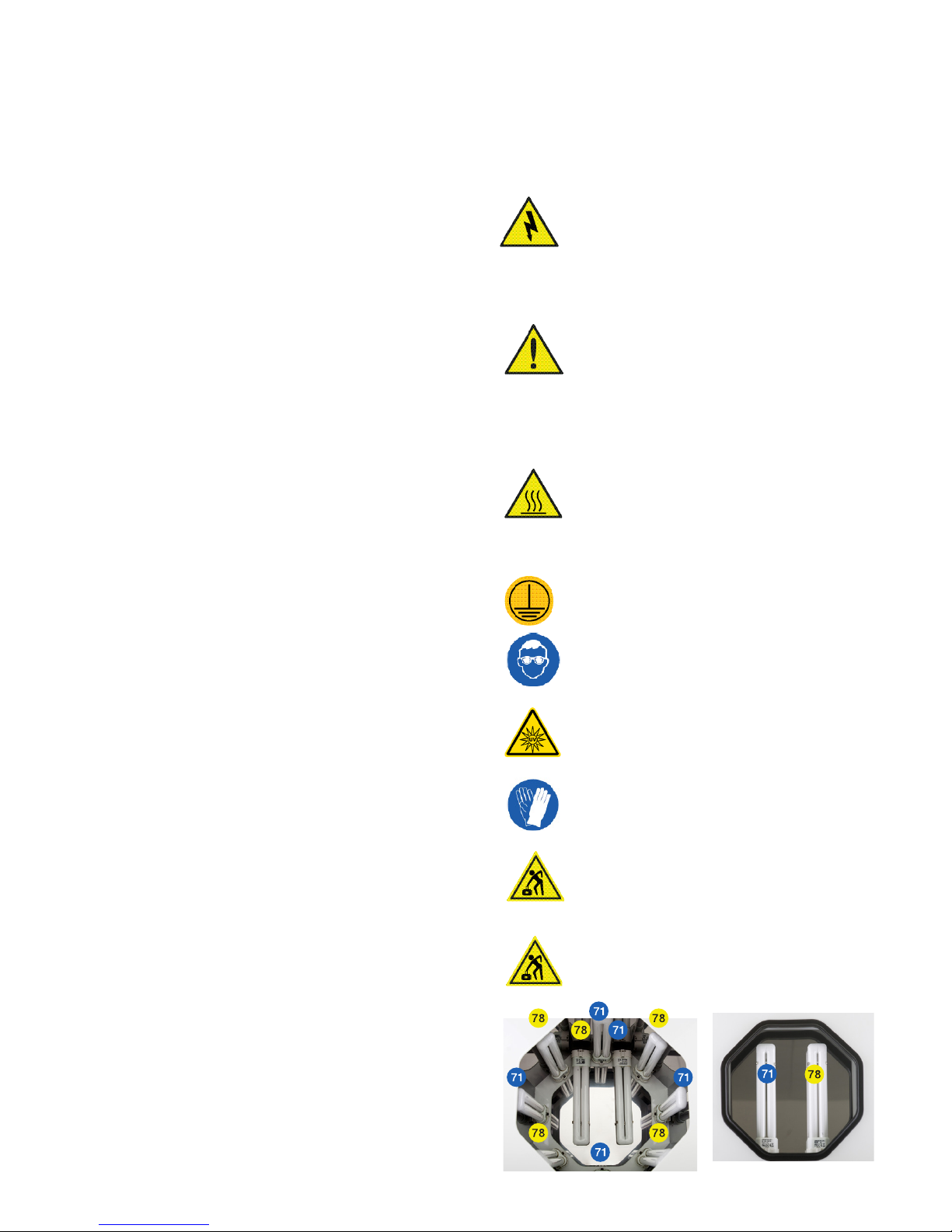
Connect all the lamps (12pcs) to all lamp sockets
which are placed in the cover and the chamber.
The recommended position of the supplied lamps
(6pcs of 18W lamps-71color and 6pcs of 18W
lamps-78color) is as shown in picture on the right.
Please make sure of rated voltage and power sup-
ply (110-240V 50/60Hz). Only the supplied power
cable can be used.
Connect the power cable with connector plug to
the power socket.
-
-
-
-
-
Safety warning label and symbol
information & Safety information
-
-
-
-
-
Do not touch live electric parts.
Turn off power source and disconnect
power cable before installing or servicing
the machine.
Turn off the machine when not in use.
Do not use worn and damaged cables.
Use only well maintained equipment.
- Keep away from children.
-Always turn off the machine before cleaning.
-Do not open the cover when machine is in use.
-Do not cover the fan at the back.
-Only use the machine with Figure 4TM, Fab-
ProTM, and NextDentTM 3D printing materials.
-
-
-
-
-
-
-
-
-
-
Wear UV protective glasses.
Do not touch the cover during operation,
this cover warms up.
Wear protective gloves.
The longest program is for 30 min. the
temperature inside the working chamber
can go up to 80°C.
Protective earth.
Wear UV protective glasses.
Caution! UV light hazard. Avoid eye and
skin exposure. Wear proper eye and skin
protection.
Wear protective gloves.
Be aware of the potential dangers of lifting
heavy loads. Ignoring this can lead to
injuries.
This device may only be lifted and moved
to its nal destination for installation by
two people.
Page 6 of 10
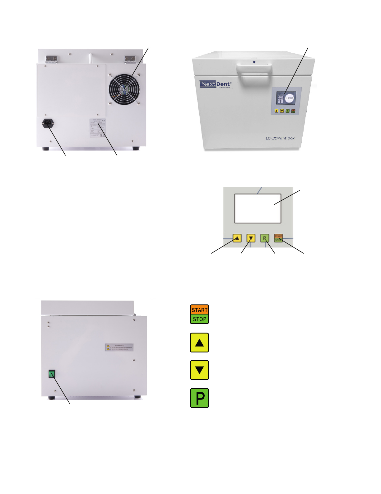
Description of function key
Start/Stop button
Start / Stop button for starting and stopping
operation.
Increasing button
Button for increasing the operation time.
Decreasing button
Button for decreasing the operation time
Program button
Program button for choosing the pre-set
programs.
(pre-set programs are: 10, 20 and 30 min)
Fan
-
-
-
The machine is equipped with a fan to cool down the
inside and maintain a proper working temperature
inside the machine.
Fan operates when the machine is in use and cool-
ing is needed.
If the fan does not work the temperature will raise
and ERROR1 will appear in the display. (see error
message)
Fuse Box and AC power cable socket
FUSE AC50V T5.0A Increase
button
Front panel
Fan
Decrease
button
Program
button
Start/Stop
button
Display / LCD
Fuze Box and AC power
cable socket
FrontRear
Front panel
Identication label
Side
Power On / Of button

Page 7 of 10
Operation
-
-
Please put the bottom plate with glass insert inside
the chamber and put a printed and cleaned object
on the glass.
Then operate the machine according to the follow-
ing program operations and the instructions for use
of the material used for printing the part.
Starting mode
Press the power switch
(green button) on the right
side of the machine.
When switching on the
machine,
the version information will
appear in the display.
After 5 seconds, the last
operation
time will appear on the
display.
Operation Mode
When the last operation time
has appeared on the display,
the user can choose a preset
time by holding the program
button. Or the user can
increase or decrease the oper-
ation time by pressing the
increase or decrease button.
Start the machine by
pressing
the start/stop button.
The time will count down
and the dots will be blinking.
(By pressing the start/stop
button, the operation time
will be memorized automat-
ically).
Stop the machine by pressing the start/stop button
again.
After operation time, the message ”End” will be dis-
played automatically. At the same time, the machine
beeps 9 times.
LC-3DPRINT BOX
welcome!
V300 1/110V
V300 1/110V
Working Progress
11/12
5/6
9/10
7/8
1/2 3/4
END
10:00
Lamp Time: 004h
Lamp Condition
Working Progress
11/12
5/6
9/10
7/8
1/2 3/4
RUN
10:31
Lamp Time: 004h
Lamp Condition
Working Progress
11/12
5/6
9/10
7/8
1/2 3/4
END
00:00
Lamp Time: 004h
Lamp Condition
Cover Inside
-
-
-
-
Lamp holding clamp
Reection plate
Lamp Socket
Silicone O-ring
Chamber inside
-
-
-
-
Cover Locking Sensor: sensor for opening and clos-
ing. The machine does not work when opened.
Lamp holding clamp
Reection plate
Lamp Socket
Metal plate with glass insert
Plate has two handles
Cover locking sensor
Lamp socket
Lamp holding clamp

Page 8 of 10
If error continues after replacing the lamps, the bal-
last must be replaced by a qualied person.
Lamp 1/2 = Ballast 1 Lamp 3/4 = Ballast 2
Lamp 5/6 = Ballast 3 Lamp 7/8 = Ballast 4
Lamp 9/10 = Ballast 5 Lamp 11/12 = Ballast 6
71 Color Lamp: 1, 3, 5, 7, 9, 11
78 Color Lamp: 2, 4, 6, 8,10,12
Always change 2 lamps 71/78 together
ERROR 5: will appear if the
the UV Lamps have burned
for 750 hours. (Lamp time).
Between the 740 and 750
hours burned the change alll
lamps message will appear
in the display. Indicating that
all lamps must be replaced
before reaching 750h.
When the 750h burning time of the lamps is reached
the machine will stop and beep, showing ERR5
The change all lamps message will appear.
Replace all lamps with new ones according to the
schedule above.
After changing the lamps reset the timer by pressing
the decreasing button for 5 seconds.
The lamp time will now read 000h.
Machine will be ready for use.
When replacing the lamps, always discon-
nect the power cable, or switch off the machine to
prevent burns. Let the lamps cool down for several
minutes before replacing them.
Maintenance
General instructions
-
-
-
-
-
Repair or maintenance of the machine, must be
carried out by qualied persons only.
Any repair or maintenance must be carried out with
ocial replacement parts supplied from the ma-
nufacturer/distributor.
Before cleaning, please remove the power plug from
the power supply.
For cleaning, please use a soft cloth with mild clea-
ning agent.
Operation of this machine must be done according
to this instructions for use.
Error message by automatic self-checking
system.
The message “OPEN” will ap-
pear on the display when a
user opens the cover during
operation. At the same time,
the machine beeps three
times.
ERROR 1: In case the
temperature around ballast
reaches over 60°C, the
machine stops automatically
and Err1 will appear on the
display.
ERROR 2: When there is a
problem with the tempera-
ture sensors, the machine
stops automatically and Err2
will appear on the display.
(contact distributor)
ERROR 3: If there is a
defective lamp, numbers
belonging to the defective
lamp or lamps will change to
red on the display. ERR3 &
Check IFU message will also
appear on the display. When
operation time elapses,
change the indicated lamps.
Always replace both indicat-
ed lamps, to insure constant
UV output. This error will also occur if the voltage is
not set to match the country supplied voltage.
Working Progress
11/12
5/6
9/10
7/8
1/2 3/4
OPEN
10:31
Lamp Time: 004h
Lamp Condition
Check IFU
11/12
5/6
9/10
7/8
1/2 3/4
ERR1
00:31
Lamp Time: 004h
Lamp Condition
Check IFU
11/12
5/6
9/10
7/8
1/2 3/4
ERR2
00:31
Lamp Time: 004h
Lamp Condition
Check IFU
11/12
5/6
9/10
7/8
1/2 3/4
ERR3
00:31
Lamp Time: 004h
Lamp Condition
Check IFU
11/12
5/6
9/10
7/8
1/2 3/4
ERR5
00:31
Lamp Time: 750h
Lamp Condition
Please note that electrical/electronic units must be disposed off separately. Do not dispose with house-
hold waste. The black bar on the “garbage bin” symbol indicates that the unit was put into circulation
after August 13, 2005. Please note that the unit is subject to regulation 2002/96/EC (WEEE) and applica-
ble following national laws and must be disposed off accordingly. Please contact your dealer if the unit
needs to be disposed of.

Page 9 of 10

Page 10 of 10
IFU ID: ILCPB201801UK PN: 40-D093, Rev B
For more information, please contact:
Warranty Hotline from the Americas
+1 888.598.1438
+1 803.326.3930
Weekdays during normal business hours or by email at
Warranty Hotline from Europe, Africa, and Middle
East (EMEA)
+44 1442.279.839
+49 6151.357.499
Weekdays during normal business hours or by email at
Warranty Hotline from Asia/Pacic
+852.8191.2453
Weekdays during normal business hours or by email at
Support-APA[email protected].
www.nextdent.com
© 2016 Vertex-Dental B.V. All Rights Reserved
NextDent” is a registered trademark of Vertex-Dental B.V. used under a tem-
porary license granted by NextDent B.V.. Neither. NextDent B.V. nor any of
its aliates is responsible for the manufacturing of the product(s).
Table of contents
Popular Dental Equipment manuals by other brands

Renfert
Renfert Waxlectric light I instruction manual

Ivoclar Vivadent
Ivoclar Vivadent Programat P700/G2 operating instructions

3Shape
3Shape TRIOS 5 Safety & Setup Instructions

Morita
Morita Signo T500 Operation instructions

erkodent
erkodent RVEERKOFORM RVE instructions

Elos
Elos Torque Wrench Instructions for use


