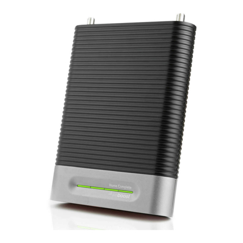
NEXTIVITY CEL-FI QUATRA EVO User manual

CEL-FI QUATRA EVO Installation and User Guide
Americas Version
MODEL NUMBERS:
NU: Q42-Z1CNU
CU: Q41-BXCU

May 2023 2
Table of Contents
I. About This Guide............................................................................................................................5
II. CEL-FI QUATRA EVO Key Features .............................................................................................6
III. Hardware Components ...............................................................................................................7
a. Network Unit (NU)....................................................................................................................8
b. Coverage Unit (CU) .................................................................................................................9
c. QUATRA EVO Fiber Hub............................................................................................................9
d. QUATRA 4000 Range Extender and Fiber Range Extender .................................................10
e. Donor Antennas.....................................................................................................................11
f. Server Antennas .......................................................................................................................12
g. Couplers ................................................................................................................................12
IV. Nextivity WAVE Portal...............................................................................................................12
V. Installation Architecture Examples ............................................................................................14
a. Real World Example 1 ...........................................................................................................15
b. Real World Example 2 ...........................................................................................................15
c. Real World Example 3 ..............................................................................................................17
d. Real World Example 4 ...........................................................................................................18
VI. Installation.................................................................................................................................19
a. Mounting the Network Unit (NU) or Optional HUB .................................................................20
b. Connecting Donor Sources to the NU....................................................................................23
c. Installing CUs CU Wall Bracket Mounting ................................................................................26
d. Cabling the NU or HUB to the CUs........................................................................................29
e. Using a QUATRA Range Extender (QRE).............................................................................31
f. Creating a Connection from your EVO to the WAVE Portal ......................................................32
g. Power on the Completely Installed System............................................................................33
VII. Commissioning and Settings on the WAVE Portal....................................................................34
VIII. Diagnostics................................................................................................................................37
a. NU and HUB LEDs ................................................................................................................37
b. CU LEDs................................................................................................................................38
c. WAVE Portal Notifications.........................................................................................................38
IX. Tips ...........................................................................................................................................41
X. Service Agreement....................................................................................................................44
XI. Helpful Tools and Signal Quality ...............................................................................................44
a. COMPASS XR and WAVE PRO App ....................................................................................44
b. WAVE Field Tool....................................................................................................................44

May 2023 3
c. Donor Signal Quality .................................................................................................................45
XII. CEL-FI Antennas.......................................................................................................................46
XIII. Specifications............................................................................................................................49
XIV. Trademarks............................................................................................................................49
XV. Warranty & Limitation of Liability ...............................................................................................49
XVI. Regulatory .............................................................................................................................49
Advanced Information – FCC/ISED RF Exposure Requirements....................................................49
XVII. Compliance............................................................................................................................50
XVIII. Glossary.................................................................................................................................50

May 2023 4
Table of Figures
Figure 1: QUATRA EVO Hardware Components and Ports .................................................................8
Figure 2: QUATRA EVO Installation with Fiber HUB ..........................................................................10
Figure 3: QUATRA Range Extender Installation.................................................................................11
Figure 4: CEL-FI Donor Antennas.......................................................................................................11
Figure 5: Server Antenna port.............................................................................................................12
Figure 6: QUATRA EVO System Architecture ....................................................................................14
Figure 7: QUATRA EVO System Architecture with Fiber Hub Option.................................................14
Figure 8: Off Air Install, 75K ft2building, Single Operator ...................................................................15
Figure 9: Off Air Install, 75K ft2building, Dual Operator......................................................................16
Figure 10: Off Air + Small Cell Install, 75K ft2building, Dual Operator................................................17
Figure 11: Larger 300K ft2Building with two NU+HUB Systems, Dual Operator ................................18
Figure 12: Antennas in Single Operator Mode....................................................................................24
Figure 13: Antennas in Dual Operator Mode.......................................................................................25
Figure 14: Small Cell Donor Input .......................................................................................................25
Figure 15: Unistrut Hardware Mounting Option...................................................................................28
Figure 16: Ceiling Tile Bracket Mounting Option.................................................................................28
Figure 17: Connecting Server Antenna or Cable ................................................................................29
Figure 18: CU port assignment on the NU ..........................................................................................29
Figure 19: QUATRA Range Extender .................................................................................................31
Figure 20: QUATRA Fiber QRE ..........................................................................................................31
Figure 21: Selecting NU Serial Number in WAVE Portal ....................................................................34
Figure 22: Registering Your NU in WAVE Portal ................................................................................35
Figure 23: New System Setup ............................................................................................................35
Figure 24: System Settings in WAVE Portal .......................................................................................36
Figure 25: Selecting Operators in WAVE Portal..................................................................................36
Figure 26: NU LEDs............................................................................................................................37
Figure 27: CU LEDs............................................................................................................................38
Figure 28: WAVE Portal Guidance Alerts ...........................................................................................40
Figure 29: Ethernet Cable Status........................................................................................................42
Figure 30: Donor Antenna Placement Guidance.................................................................................42
Figure 31: LPDA-R Antenna ...............................................................................................................46
Figure 32: Wideband Directional Antenna ..........................................................................................46
Figure 34: (Low-Profile) LP SISO Indoor Omni Antenna.....................................................................48

May 2023 5
I. About This Guide
There are a variety of CEL-FI QUATRA product variants available, supporting a variety of band
configurations, for multiple regions. This manual is applicable to the CEL-FI QUATRA EVO
M/N: Q42-Z1CNU and Q41-BXCU only and does not apply to any other QUATRA variant.
Model Numbers:
NU: Q42-Z1CNU
CU: Q41-BXCU
Safety Precautions
• Use CEL-FI QUATRA EVO indoors. It should not be used outdoors.
• These products are designed to be used with the internal power supply unit that shipped
with the Network Unit. When installing the equipment, all the requirements of the
manufacturer and the referenced standards must be met.
• There are no user-serviceable parts inside.
Note
Changes or modifications to this product not expressly approved by Nextivity may void your
right to operate the equipment.

May 2023 6
II. CEL-FI QUATRA EVO Key Features
•Carrier Grade, FCC-certified Part 20 Smart Signal Booster (operator Retransmission
Agreements are not required)
•Support for AT&T, Verizon, and T-Mobile (other operators may be requested)
•Relays four bands for one (1) operator, or two bands for each of two operators
•Independent operator donor ports allow for independent operator optimization
•Single combined (CU) server port enables driving either a serving antenna or passive DAS
field
•100 dB max system gain per channel
•Support for up to six (6) CUs (twelve with a HUB)
•N-type(f) RF connectors (donor and server)
•Internal modem for remote management (SIM slot access)
•Industrial aluminum powder-coated housing
•Up to 100m cable distance between NU and CU (using Category cable)
•QUATRA Range Extender (QRE) doubles CU cable length (up to 200m)
•The Fiber QRE can further extend CU cable length an additional 2km
•20-22 dBm uplink power per operator per band
•up to 16 dBm downlink power per cellular channel
Deploy With Confidence
CEL-FI QUATRA EVO is designed to improve indoor signal coverage without any risk of
interference to the mobile network. CEL-FI QUATRA EVO provides a sophisticated network-
safe solution that has been rigorously tested globally, through multiple generations, and
engineered to deliver multiple levels of network protection:
• Uplink gain and power control to prevent desensitizing the network
• Echo-cancellation and feedback control to prevent oscillation of the system
• Uplink muting, when handset (UE) use is not detected
• Signal qualification (channels are individually qualified, so noise or very poor signals won’t
be amplified and degrade the network)
• The CEL-FI WAVE Platform cloud-based portal enables remote monitoring of the
equipment and network KPI’s, such as channel configurations, RSRP, RSRQ, SINR, and
system gains, providing control and optimization insight.
Single Operator Mode:
DONOR ANTENNA PORTS
Ports A plus C
AT&T
2 + 4 + 5 + 12
T-Mobile
2/25 + 4 + 5 + 12
Verizon
2 + 4 + 5 + 13
Other operator configurations
Band options as indicated in Settings

May 2023 7
Dual Operator Mode Examples:
DONOR ANTENNA PORTS
Port A
Port C
AT&T + Verizon
AT&T 2 or 4 + 5 or 12
Verizon 13 + 2 or 4
T-Mobile + AT&T
AT&T 2 or 4 + 5 or 12
T-Mobile 2 or 4
T-Mobile + Verizon
T-Mobile 2 or 4 + 5 or 12
Verizon 13 + 2 or 4
Other operator configurations
Band options as indicated in Settings
III. Hardware Components
CEL-FI QUATRA EVO is a modular solution with two (2) foundational components: the
Network Unit (NU) and the Coverage Unit (CU. In traditional DAS terminology, these could be
known as the Head End (NU) and the Remote Unit (CU).
The signal sources are brought into the system at the NU, via a wired connection through a
donor antenna or small cell RF connection. Those signals are digitized and individually
processed and sent to the CUs for retransmission, each normalized to full coverage power.
Power is provided to the entire system through AC power at the NU. The CUs are powered via
Power over Ethernet (PoE), and therefore do not require a separate power source at their
location.

May 2023 8
Figure 1: QUATRA EVO Hardware Components and Ports
a. Network Unit (NU)
The NU is the head end for the QUATRA EVO system. The signal sources (one for each
port/operator) are connected to the NU. Then they are digitized and distributed over two
Category cables to each CU, along with power (PoE) for the CU.
QUATRA EVO NU
Note
Only cellular signals may be connected to the donor ports. Other types of radio signals will not
work and may damage the system.
The NU has two (2) N-type(f) RF ports on the top for operator donor signals.
There are two (2) SMA(f) ports on the top of the NU. One functions as the external antenna
connection for the unit’s internal cellular modem (CELL), and the other is for GPS. The GPS
port is unused (future functionality).
Power
•AC Power Supply (inside the NU)
•AC power cord
Physical Interface
•RJ45 ports (13)
•Twelve RJ45 ports (2 for each of the 6 CUs)
•One LAN port for remote management
•SFP+ module dock (for use with a Fiber HUB)
•N-type(f) RF Ports (2) for Donor Antennas
•SMA(f) ports (2 for the internal LTE modem)
User Interface
•LED interface (front) to indicate system status
•Power
•CU1
•CU2
•CU3

May 2023 9
•CU4
•CU5
•CU6
•SFP+
•LAN
•MODEM
Power Supply Cable
b. Coverage Unit (CU)
The CU receives the digitized cellular signal from the NU, converts them back to RF, then
amplifies and distributes the service from its N-type(f) RF port. Service can be deployed
through a single connected antenna, or through a DAS field.
QUATRA EVO CU
c. QUATRA EVO Fiber Hub
The Fiber Hub expands Network Unit capacity from six to up to twelve Coverage Units. The
Fiber Hub may be installed next to the NU, or in another area of the building to be covered. It
also may be installed up to 2.0 km (1.24 M) away from the NU in another building, or it may be
used with a NU to create a fiber optic link to remote the donor antennas. The Hub uses SFP+
modules (not included) and may accommodate MMF or SMF cabling.
Note that the QUATRA EVO HUB is not compatible with other QUATRA 4000 Series HUBs.

May 2023 10
QUATRA EVO FIBER HUB
Model Number: Q40-Z1FNU
Figure 2: QUATRA EVO Installation with Fiber HUB
d. QUATRA 4000 Range Extender and Fiber Range Extender
The QUATRA Range Extender (QRE) unit is a device that extends the standard 100-meter
category cable length from NU to CU up to 200 meters. It is installed halfway along the NU to
CU cable and requires no external power. There are two RJ45’s on the input (NU) side, and
two RJ45’s on the output (CU) side. Traditional Ethernet extenders do not understand
QUATRA signaling and will not work with QUATRA.

May 2023 11
The QUATRA Fiber Range Extender (fQRE) system is a similar product that converts
QUATRA EVO specific signaling to optical fiber and then back to category cable for up to an
additional 2km of CU cable length. See fQRE product information at www.nextivityinc.com for
more information about the fQRE.
Note that the QUATRA 4000 QRE and fQRE work with either the Q4000/i/c or EVO models.
QUATRA 4000 QRE
Figure 3: QUATRA Range Extender Installation
e. Donor Antennas
The donor antennas provide off-air signals to individual operator donor input ports. The
objective is to provide the best quality operator signals to the NU. A variety of donor antennas
are available from Nextivity. The right donor antenna choice can make the difference between
a good outcome and a great outcome. Please refer to other antenna-specific documents for
choosing the right donor antenna.
CEL-FI Donor Antennas - Model Numbers A32-V32-201 (WBD) and A62-V44-201 (LPDA-R)
Figure 4: CEL-FI Donor Antennas
Nextivity recommends its LPDA-R antenna for use as a great donor antenna for most
situations. Learn more about our Antenna options.

May 2023 12
f. Server Antennas
Server antennas connect to the N-type(f) RF port on the CU.
Figure 5: Server Antenna port
A variety of Server antennas are available from Nextivity. Visit the Antenna Product page for
details and updates.
g. Couplers
RF couplers or tappers may be used with CUs when multiple service antennas are desired.
Careful system design should be implemented to ensure sufficient radiated power for all
antennas. Couplers should be specified that are appropriate for the power and frequency
bands that EVO supports.
IV. Nextivity WAVE Portal
The WAVE Portal is Nextivity’s SOC2 Type 1 compliant cloud-based software platform from
which CEL-FI apps and connected devices are hosted and driven. Current-generation CEL-FI
products feature embedded connectivity that allows them to connect to the WAVE cloud. The
WAVE Portal and apps facilitate software updates, registration, commissioning, installation,
optimization, and troubleshooting. The CEL-FI WAVE platform continues to expand in features
and function.
In order to use the WAVE Portal and related capabilities, you must be registered with the
system.
•Request Access to the WAVE Portal
•Log In to the WAVE Portal
The portal constantly monitors your systems and tells you how to resolve alarms or improve
performance with explicit guidance, all from your smartphone or computer browser. See CEL-
FI training modules for easy-to-understand videos and slide tutorials.
The internet/portal connection method should be determined and prepared for prior to
installation. This will ensure that the portal is connected and available for
commissioning and settings.
Some of the many things the portal can do:
•Configure your EVO single or dual operator port assignments
•Monitor system health and display, email, or text alarm notifications

May 2023 13
•Manage Settings remotely (sale and service lease functions)
•Real-time performance tips for best performance, based on your system data
•Remote troubleshooting with hourly KPI measurements – Saves time and money,
without a truck roll
•Helps you take coverage measurements and generate reports with the COMPASS XR
unit
•Keeps your software up to date, so you always have the latest features
•Maps your systems so you know where they are (global)
•Data archive for all of your site documents, including floorplan-system layouts

May 2023 14
V. Installation Architecture Examples
Figure 6: QUATRA EVO System Architecture
Figure 7: QUATRA EVO System Architecture with Fiber Hub Option

May 2023 15
a. Real World Example 1
In this example, the CEL-FI QUATRA EVO is providing wireless coverage for a single cellular
operator in a six story 75,000 ft2building. A donor antenna is located on the top of the building
to ensure the best signal-to-noise ratio for the cellular operator, and the signal is split to feed
both donor inputs on the NU. A CU is placed on each floor, and a distributed antenna system
(DAS) field is run out from each CU to provide great coverage.
Figure 8: Off Air Install, 75K ft2building, Single Operator
b. Real World Example 2
In this example, the CEL-FI QUATRA EVO is providing wireless coverage for two cellular
operators in a six story 75,000 ft2building. Individual operator donor antennas are located on
the top of the building to provide signals to each operator donor port, ensuring the best signal-
to-noise ratio for both cellular operators. A CU is placed on each floor, and a distributed
antenna system (DAS) field is run out from each CU to provide great coverage.

May 2023 16
Figure 9: Off Air Install, 75K ft2building, Dual Operator

May 2023 17
c. Real World Example 3
In this example, CEL-FI QUATRA EVO is providing wireless coverage for two cellular
operators in a six story 75,000 ft2building. Operator #1 (donor port A) is using an Off-Air donor
antenna because the donor signal outside the building is healthy. However, Operator #2
(donor port C) is using a Small Cell signal source, because the outdoor donor signal was
inadequate. A CU is placed on each floor, and a distributed antenna system (DAS) field is run
out from each CU to provide great coverage.
Small Cell attenuation of 60-80 dB is typical, however it depends on the small cell (target
RSSI/RSRP at the QUATRA EVO donor port should be -50dBm/-80dBm respectively after
attenuation). Consult the Small Cell Guide or contact Support for more information.
Figure 10: Off Air + Small Cell Install, 75K ft2building, Dual Operator

May 2023 18
d. Real World Example 4
This building uses two donor antennas - one for each operator. The donor feeds are split two
ways to feed the two systems. Each QUATRA EVO NU is connected to a HUB, and the NUs
and HUBs are connected to CUs throughout the building, and then each CU is connected to a
DAS field, providing coverage to the building.
Figure 11: Larger 300K ft2Building with two NU+HUB Systems, Dual Operator

May 2023 19
VI. Installation
Note
Before any permanent installation, make sure all the components are planned and accounted
for, as well as any wiring, cabling, power, mounting, antenna placements, and portal system
access.
Overview
Several things need to be determined as part of installation planning and preparation.
•Perform a Site Survey with a measurement tool, such as the COMPASS XR and WAVE
PRO app, to determine current cellular service issues, candidate donor antenna locations,
and where hardware and cabling may be installed. See COMPASS XR product
documentation for more information.
•Plan the system using the CEL-FI online BOM Estimator or a tool such as iBwave, and your
knowledge of the building floorplan and cable routing options. Where will CEL-FI hardware
be mounted (NU, CUs, antennas, and optional HUBs or Extenders)? This includes a
suitable power outlet for the NUs or HUBs. Visit the Nextivity Partner Portal or CEL-FI
University for more information.
•Install all system hardware according to the plan.
•Cable the system, including NU-CU category cables, and donor and service antennas and
cables.
•Connect the system to the cloud and commission it on the WAVE Portal (New Systems
page) or use the many features in the WAVE Field Tool (WFT) Windows PC program.
•Use the hardware LEDs, troubleshooting table in this guide, and the WAVE Portal to
resolve any issues.
•Monitor and manage your system remotely using the WAVE Portal.
Note
For signal surveys, or to find candidate locations for donor antennas, or aim donor antennas,
we recommend Nextivity’s COMPASS XR tool and WAVE Pro app (WPA). Ask your distributor
for more information or visit us at www.nextivityinc.com
Note
IBWAVE or the Nextivity BOM Estimator design tool (or other RF planning tools) are not
required but are a good way to ensure the best performance outcomes. iBwave vex and
template files may be found on the Nextivity Partner Portal pages. There BOM Estimator tool
may be accessed through Nextivity Partner Portal.

May 2023 20
a. Mounting the Network Unit (NU) or Optional HUB
The CEL-FI QUATRA EVO NU and HUB are designed for simple wall or rack mounting -
typically in an IT room with coaxial cable riser access to where the donor antennas are to be
mounted (usually on the roof, or another exterior location with a quality donor signal from each
cellular operator). The location should also have an available electrical outlet within reach of
the supplied NU or HUB power cord.
Mounting accessories, including screws and anchors, for common material types (drywall,
plywood, etc.) are included with each NU and HUB.
Wall Mounting
The following tools are recommended:
•Power drill/screwdriver
•Drill bit extender (3”+)
•Hammer
•Pencil, or another similar marker
•Level
Caution
Make sure the area behind any surface is free of electrical wires or other dangerous elements
prior to drilling.
The QUATRA EVO NU and HUB have four (4) secure mounting tabs, two on each side. The
two topmost tabs have been key-holed, allowing the unit to be lifted onto pre-installed screw
heads.
Note
The Mounting Instructions below use the standard drywall mounting anchors and screws
included with the unit. If the NU or HUB are to be mounted onto other surfaces, make sure the
appropriate anchors and screws are used (not included).
This manual suits for next models
2
Table of contents
Other NEXTIVITY Extender manuals
NEXTIVITY
NEXTIVITY Cel-Fi GO User manual
NEXTIVITY
NEXTIVITY Cel-Fi GO+ User manual
NEXTIVITY
NEXTIVITY Cel-Fi GO X Smart Signal Booster User manual
NEXTIVITY
NEXTIVITY Cel-Fi PRIME User manual
NEXTIVITY
NEXTIVITY Cel-Fi QUATRA User manual
NEXTIVITY
NEXTIVITY Cel-Fi QUATRA RED User manual
NEXTIVITY
NEXTIVITY CEL-FI GO G43 User manual
