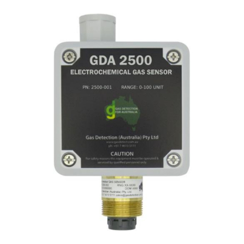
OneTemp GDA 4350 User manual

GDA 4350
Carbon Dioxide Sensor
Operating Manual
Manual Revision: 1.1
Hardware Version: 11, 12
Software Version: 2.1.3
© Copyright Gas Detection (Australia) Pty Ltd 2018

Page 2 of 16 M-GDA-4350 V12 Rev 1.1
Thank you for purchasing this product from Gas Detection (Australia) Pty Ltd
This manual contains information about the method of installation, simple maintenance and
troubleshooting of the GDA 4350 gas sensor. Please read it carefully and keep it nearby
for further reference.
Note:
The calibration period for a sensor will depend on a number of factors such as the
environment in which it is used, operating temperature, humidity, atmospheric pressure
and environmental pollutants.
In all cases we recommend sensors are calibrated in line with target market legislation.
In order for these sensors to maintain operational efficiency and performance it is
recommended that the sensors are checked for functionality on 6 monthly periodic cycle.
A sensor calibration should be carried out annually, by fully trained and authorised and
approved technicians approved by GDA.

Page 3 of 16 M-GDA-4350 V12 Rev 1.1
PROPRIETARY RIGHTS
No part of the hardware or documentation may be reproduced, transmitted, transcribed, stored
in a retrieval system, or translated into any language or computer language, in any form or by
any means, without prior written permission of GDA.
While great efforts have been made to ensure the accuracy and clarity of this document, GDA
assumes no liability resulting from any omissions in this document, or from misuse of the
information contained herein. The information in this document has been carefully checked
and is believed to be entirely reliable with all of the necessary information included. GDA
reserves the right to make changes to any products described herein to improve reliability,
function, or design, and reserves the right to revise this document and make changes from
time to time in content hereof with no obligation to notify any persons of revisions or changes.
GDA does not assume any liability arising out of the application or any use of any product or
circuit described herein; neither does it convey license under its patent rights or the rights of
others.

Page 4 of 16 M-GDA-4350 V12 Rev 1.1
Table of Contents
1. Overview ....................................................................................................................................................5
1.1. Introduction.............................................................................................................................................. 5
1.2. Specifications............................................................................................................................................ 6
2. Sensor Placement.......................................................................................................................................7
3. Wiring Instructions .....................................................................................................................................8
4. Operation ...................................................................................................................................................9
5. Output Configuration ...............................................................................................................................10
6. Calibration:...............................................................................................................................................11
6.1. Fresh air Zero point Calibration:............................................................................................................. 11
7. Revision History .......................................................................................................................................16

Page 5 of 16 M-GDA-4350 V12 Rev 1.1
1. Overview
1.1. Introduction
The GDA 4350 is designed for use in safe area applications. It uses the latest laser
semiconductor technology for detection of carbon dioxide. The sensor and electronics are one
homogenous unit and must never be separated. It has an analog output which can be set to 4-
20mA, 0-20mA, 0-10V or 0-5V.
116 mm
130 mm
72 mm
Figure 1: Dimensions

Page 6 of 16 M-GDA-4350 V12 Rev 1.1
1.2. Specifications
Model
GDA 4350
Detectable Gases
Carbon Dioxide (CO2)
Detectable Gas Ranges
0-2000ppm; 0-10000ppm; 0-5% vol; 0-20% vol; 0-100% vol
Detection Type
Diffusion
Sensor Technology
Non Dispersive Infra red (NDIR)
Linearity
Linear
Response Time
< 24 seconds at STP
Accuracy of Reading
± 2% FSD ±0.5% reading @STP
Warm Up Time
< 4 min
Zero Drift
<0.5% FSD for 90days @STP
Calibration Drift
<0.5% FSD for 90 days @STP
Calibration Requirement
Annually if sensor operated at STP
Operating Voltage
+24VDC
Output Type
4-20mA (Standard), 0-20mA, 0-10V or 0-5V (User
Specified)
Power Consumption
150mA peak @ 24VDC
Connection
4 pin plug connector
Wiring
3 core wire with overall screen with current carrying
capability to suit cable length of cable run, Screen must be
connected to the Earth connection on the connector P1.
Output Specifications
4-20mA (Standard), 0-20mA, 0-10V or 0-5V (User
Specified)
Operating Temperature
5°C to +45°C (LT version to -20°C to +45°C)
Operating Humidity
5% to 95% RH peak non condensing
Operating Pressure
950 to 1050 hPa
Cable Entry
User defined (Top or Left side pre cut)
Mounting Height
Approximately 300mm above the floor
Enclosure Material
ABS plastic
Dimensions
115 x 130 x 71 (W, H, D)
Weight
300g
IP Rating of Enclosure
IP50
Table 1: Specifications

Page 7 of 16 M-GDA-4350 V12 Rev 1.1
2. Sensor Placement
The sensor is rated IP50 and therefore suitable for indoor use only. If it is going to be used in
external environments seek specialist advice from GDA. The sensor should not be exposed to
steam or saturated water vapour.
Carbon Dioxide is heavier than air and therefore will (if there is no air movement) fall to lower
levels. The recommended minimum installation height above the floor is 300mm.
Mount the sensor as close as possible to where the leak of the gas being detecting may occur
as the distance from a potential leek effects the time taken to detect it. The further from the
potential leeks the more the gas will be diluted. Take into account drafts and air movements
when mounting the sensor.
Fit using the four fixing holes in the corners of the box. When drilling avoid any vibration of the
sensor unit. The laser diode sensing unit is very sensitive. Do not expose the sensor to any
mechanical shock.
IT IS VERY IMPORTANT THAT THE GDA 4350 IS INSTALLED IN THE MOST UPRIGHT
POSITION AGAINST A VERTICAL STRUCTURE.
YES (Recommended)
NO NO
For other mounting positions other than recommended please contact Gas Detection
(Australia). The sensor will need to be recalibrated if an alternate mounting position is
required. Do not mount the sensor with the opening facing up, as CO2gas can accumulate in
the sensor and cause false readings.
Figure 2: Sensor Mounting orientations

Page 8 of 16 M-GDA-4350 V12 Rev 1.1
3. Wiring Instructions
The sensor electrical connection is on the rear of the faceplate via a 4 pin polarised plug on
the PCB.
The sensor is to be wired with a 3 core cable with an overall screen with current carrying
capability to suit cable length of cable run. Screen must be connected to the Earth connection
on the connector P1. The enclosure is platted with a layer of conductive chrome which is
connected to the earth terminal on the PCB.
The 4-20mA O/P is to be connected to the 4-20mA input of the control board.
+V
+24 VDC
O/P
Earth
Output 4-20mA
Cable Screen
Figure 3: Sensor Wiring Diagram
Protection
Cover Plate
Power and
Output
Connector
P1
0 VDC
GND

Page 9 of 16 M-GDA-4350 V12 Rev 1.1
4. Operation
When power is applied the sensor goes through a power up procedure as detailed below.
Please note that the current o/p is not valid for approximately 2-4 minutes from the
power being applied.
During the 2-4 minute power up the current output of the GDA 4350 may reach the full
scale of the set output. Ensure that this does not affect external equipment.
LED
LED STATE
FUNTION
ON
Power is present
OFF
Power is not present
GREEN ON, BLUE
FLASHING,
YELLOW ON
The sensor is in its warm up period (approx 2~4
mins) during this period the sensor o/p is 0.45mA
GREEN ON, BLUE
FLASHING
Normal operation the sensor has stabilised and
the 4-20ma reflects the amount of gas present
GREEN & RED ON
This indicates a fault associated with the sensor.
The o/p current is reduced to 1.2ma
Table 2: LED Status
Figure 4: Status LED Location

Page 10 of 16 M-GDA-4350 V12 Rev 1.1
5. Output Configuration
Current or Voltage 0-20mA, 4-20mA, 0-5V, 0-10V Configuration
This output will generate a current or voltage output reflecting the full scale of the sensor. This
output is factory set and calibrated to the user’s specified requirements at point of purchase.
If an output type was not specified by the user at time of purchase the default setup is set and
calibrated to 4-20mA. This is user adjustable out in field but will not be as accurate to what it
was originally calibrated to from factory.
The 4-20ma will drive into a maximum of 680Ω load impedance (line and input impedance) at
24V.
Be cautious when handling the GDA 4350 as there are delicate components that can
easily be damaged by static discharge. Always observe anti static precautions.
To change the output:
1. Isolate the GDA 4350 by removing the incoming power source connector (P1) from the
rear of the board
2. Adjust jumper pins to the desired output configuration (see Table below)
3. Ensure output is configured for the changed output option
4. Revert to normal operation
Output Type
P2 Jumper Configuration (IN or OUT)
P2 Jumper Location
1
Sen
Pwr
2
MCU
Pwr
3
HS/FS
4
0/4-
20mA
5
V Out
6
Reset
4 - 20 mA (Default as
pictured)
IN
IN
IN
IN
OUT
OUT
0 - 20 mA
IN
IN
IN
OUT
OUT
OUT
0 - 5 V
IN
IN
OUT
OUT
IN
OUT
0 - 10 V
IN
IN
IN
OUT
IN
OUT
Table 3: Output Jumper location
P2
P3
P2 Jumper
Description
P1
P2 Jumper Location No.:
1 2 3 4 5 6

Page 11 of 16 M-GDA-4350 V12 Rev 1.1
6. Calibration:
Sensors are issued tested & pre-calibrated under controlled lab conditions. Changes to
humidity, temperature, and other environmental factors affect the sensor accuracy and may
need a re-set of the fresh air zero point when introduced to new environments.
The GDA 4350 is an auto calibrating device and under most cases will auto calibrate to new
environment over time.
Functional testing may be carried out with a suitable test gas to ensure that the 4-20mA o/p
corresponds with the gas level. This should be undertaken when the unit is fully assembled
and using a flow rate of ~0.5L/min of the target gas. Test gas and equipment are available
from Gas Detection Australia.
6.1. Fresh air Zero point Calibration:
A manual fresh air zeroing (span) of the sensor can be performed when the sensor has been
powered for a minimum of one hour. The fresh air zero can be performed when the sensor is
in a known fresh air. The sensor must be in the fresh air conditions for a minimum of five
minutes or until the output has reached a stable point.
To perform a manual fresh air zero (span) point calibration:
1. Remove the GDA 4350 from the wall to access the back of the sensor unit;
2. Add a jumper to pins 1 and 3 of P3 see picture below, This enters Manual Calibration
Mode (see table for LED sequence);
3. Press and hold the SPAN/ Fresh Air Zero calibration button S1 for 1 to 2 seconds
(see table for LED sequence):
If the Fresh Air Zero was successful (see table for LED sequence)
If the Fresh Air Zero was NOT successful (see table for LED sequence). Repeat step 3
after ensuring that the sensor is in fresh air and stable.
Note: Do not press the ZERO button as it will perform a Nitrogen zero.
4. When successfully zeroed remove the Manual Calibration jumper from header P3 and
return to normal operation.
Mode
LED Light Sequence
Manual CAL Mode
Solid while jumper in Manual
CAL position
Performing Zero
0.5 sec
Alternate blinking at once per
second for ~ 4 sec
Zero Successful
0.1 sec
Fast blink for ~ 2 sec
Zero Failed
Solid for > 2 sec
Table 4: Calibration LED sequence

Page 12 of 16 M-GDA-4350 V12 Rev 1.1
Contact OneTemp for more information if calibration of sensor is required
Manual Calibration
Mode: Add a jumper
to pins 1 and 3 of P3
1 3
Use supplied
jumper on pins 18
and 17 of P3 for
Manual Calibration
Mode, return to this
location only.
Figure 5: Manual Calibration Mode jumper position
Figure 6: Fresh Air Zero button location
LED Colours:
SPAN/ Fresh Air Zero
calibration button S1

Page 13 of 16 M-GDA-4350 V12 Rev 1.1
Label interpretation:
1. Product: Name of detectable gas and its chemical formula
2. Part Number: Product part number of detector, sensor head, controller, ...
3. Serial Number: Serial number of detector, sensor head, controller, ...
4. Range: Range of sensor and units (ppm, %vol, %LEL)
5. Date of Manufacture: Date of Manufacture/ Date of Calibration
Figure 7: Label interpretation
1:
2:
3:
4:
5:

Page 14 of 16 M-GDA-4350 V12 Rev 1.1
Notes

Page 15 of 16 M-GDA-4350 V12 Rev 1.1
Notes

Page 16 of 16 M-GDA-4350 V12 Rev 1.1
7. Revision History
Version
Contents
Date
1
Initial revision of the Manual HW: V11-12
27 Apr, 2018
1.1
Manual CAL table 4 updated
1 May, 2018
Table 5: Revision History
This product and operating manual are subject to change without prior notice for the
improvement of product performance and ease of use.
Table of contents
Other OneTemp Gas Detector manuals
Popular Gas Detector manuals by other brands

AGS
AGS Merlin GDP2X Installation & operation manual

LaserLiner
LaserLiner BBQ-GasCheck operating instructions

Dräger
Dräger X-AM 5000 Instructions for use

Siemens
Siemens QRB1 Series manual

RKI Instruments
RKI Instruments 61-1004RK Operator's manual

Crowcon
Crowcon IRmax Installation, Operating and Maintenance Instruction

Gnutti Group
Gnutti Group TiEmme 2082R manual

Bieler+Lang
Bieler+Lang ExDetector HC 150 Operating and installation instructions

UE
UE VANGUARD WirelessHART TCD50H1A Installation and maintenance instructions

Oldham
Oldham OLCT 20 user manual

Trolex
Trolex Sentro 1 user manual

Ludlum Measurements
Ludlum Measurements 43-37 manual