Nexus 21 L-45 User manual

TV Lift System Model L-45
Installation Instructions

2
Contact: Sup[email protected]
Toll Free: (866) 500-5438
Phone: (480) 951-6885
Fax: (480) 951-6879
Revised: 6/23/15
Below is a parts list describing all of the items included with the Model L-45 Lift System. You may also
wish to refer to the dimensional diagram shown on “Supplemental Page A” (at the end of this
document).
Before beginning assembly and installation, please make sure that you have all items included on the
list. If any parts are missing or damaged, please contact Nexus 21. Our contact information is shown
at the top of this page.
Parts List
1. L-45 Lift Column 2. Screen Support Bracket 3. Base Plate Bracket (2)
(28 ¾” x 7” x 3 ¾”) (6.4 ”x 15.7”) (6 ¼” x 2”)
4. Upper Support Bracket 5. Upper Support Bracket Base 6. Screen Back Plate
(3”x 3 ½”) (5 1/8” x 7”) (32” x 9”)
7. Lower Support Bracket 8. Top Plate Bracket 9. Vertical Mounting Bars (2)
(10” x 4” x 2 ½”) (18” x 4 ½- 6 ½”) (20” x 1”)
NOTE: Items 6 & 9 are included in the “Nexus 21 Standard TV Mount” package.

3
Parts List, continued
10. Control Box 11. Top Support Brackets (2) 12. Assorted TV Mounting Screws
(10 ½” x 3 ¾” x 1 ½”) (14” x 2 ¾”) (6 ½” x 4”)
Cables
Motor Cable –Black cable with white, six-pin plugs. Use this cable to connect the Lift Column to the Control Box
(using slot #1 on the Control Box). Three feet long.
Power Cable –Connects Control Box to power outlet. Three feet long.
RF Cable (only present if you ordered the RF version of the Lift System) –Use to connect the RF Receiver to the
Control Box. Ends have telephone-style connectors. One foot long.
Hardware
13.Two (2) -- Screen Locks (In bag labeled PDM-0108 - Located in box with Part #5 and #6)
14. Eight (8) -- 6mm x 16mm Flat Head Machine Screw
15. Sixteen (16) -- 6mm x 12mm Button Head Machine Screw
16. Two (2) -- 1½” x ¼” Steel Threaded Taper Pins (For Floating Top)
17. Four (4) -- 3/8 - 16 x ¾” Button Head Machine Screw
19. Two (2) -- #10 x 1 ¾” Flat Head Wood Screw
20. Eighteen (18) -- #10 x ¾” Truss Head Wood Screw
21. Four (4) -- #8 x ¾” Flat Head Wood Screw (For IR controls only)
22.RF Controls or IR Controls (see explanation on page 6)
23.Two (2) -- Allen Wrenches –4mm and 7/32”
24.One (1) -- “Snakeskin” Wire Management Sleeve – 4 feet long
25.Three (4) -- Velcro end Ties, for use with Wire Management Snakeskin
26.Three (4) -- Plastic Ties, also for use with Wire Management Snakeskin
27.Four (4) -- Square Multi Mount Washers
28. Four (4) -- Wire Clips
29. Four (4) –Lid Catch Brackets w/ (8) #10 x ¾” THWS
Wire Management
The Lift System has no exposed gears or moving parts that can
damage your wires, so wire management is simple. We have
included a four-foot long “SNAKESKIN” sleeve, which is a state-of-
the-art wire bundling and protection system (the sleeve can be cut
shorter if you wish). The System also includes 4 Velcro end ties and 4
plastic ties. Use the Velcro ties at the ends of the SNAKESKIN, to
close the ends of the sleeve and to keep the wires together inside it.
Use the plastic ties to fasten the cable bundle in a fixed position, so it
moves up and down with the lift.

4
SAFETY INFORMATION
SEVERE PERSONAL INJURY AND PROPERTY DAMAGE CAN RESULT FROM IMPROPER INSTALLATION
OR ASSEMBLY. READ THE FOLLOWING WARNINGS BEFORE BEGINNING:
WARNINGS:
1. Do not use this product for any application other than those specified by Nexus 21.
2. Do not exceed the weight capacity. This can result in serious personal injury or damage to the equipment. It is the installer’s
responsibility to ensure that the total combined weight of all attached components does not exceed that of the maximum
figure stated.
3. Follow all technical specifications and instructions during the installation.
4. Only use attachments/accessories specified by the manufacturer.
5. Close supervision is necessary when this system is being used by, or near, children, or disabled persons.
6. It is the responsibility of the installer to warn all potential users of the dangers of interfering with the mechanism during
operation.
7. Read all technical instructions fully before installation and use. It is the installer’s responsibility to ensure that all
documentation is passed on the users and read fully before operation.
8. Failure to provide adequate structural strengthening, prior to installation can result in serious personal injury or damage to
the equipment. It is the installer’s responsibility to ensure the structure to which the Lift System is affixed can support four
times the weight of the system.
9. Risk of electric shock. Do not attempt to open the Control Box.
10. To reduce risk of fire or electric shock, do not expose parts to rain or other liquids.
11. Protect the power cord from being walked on or pinched.
12. Keep all documentation.
13. Heed all warnings.
14. Clean only with a dry cloth.
15. Refer all service questions to Nexus 21 if the system does not operate normally.
Nexus 21 disclaims any liability for modifications, improper installations, or installations over the specified weight range. Nexus 21 will not be liable for
any damages arising out of the use of, or inability to use, Nexus 21 products. Nexus 21 bears no responsibility for incidental or consequential damages.
This includes, but is not limited to, any labor charges for the servicing of Nexus 21 products performed by anyone other than Nexus 21.
Nexus 21 intends to make this and all documentation as accurate as possible. However, Nexus 21 makes no claim that the information contained herein
covers all details, conditions or variations, nor does it provide for every possible contingency in connection with the installation or use of this product. The
information contained in this document is subject to change without prior notice or obligation of any kind. Nexus 21 makes no representation of
warranty, expressed or implied, regarding the information contained herein. Nexus 21 assumes no responsibility for accuracy, completeness or
sufficiency of the information contained in this document.
CABINET LID HAZARD
TV HAZARD
CAUTION: Avoid contact with the TV and Lift System during
operation. Use with caution.
CAUTION: The cabinet lid must be installed as described in the
instructions, using the Steel Threaded Tapered Pins. Installing
the cabinet lid in any other fashion will create hazardous pinch
points that can cause serious personal injury.

5
Types of Controls for Nexus 21 Lift Systems
All Nexus 21 Lift Systems come standard with a wireless remote control and receiver. We offer a choice of two different
type of remotes: IR and RF (both of which are explained in detail below). Our standard control type is RF, so unless you
specifically requested the IR version when you made your purchase, you probably received the RF controls with this Lift
System. The method of installation for each type of remote control is slightly different, so you should now identify which
type of remote you have by reading below, and then follow the instructions for that type of remote.
NOTE: If you will be using the Lift with a home control system (like the ones made by companies such as Crestron or
Control 4) the most common form of control is to WIRE IT DIRECTLY to the relays of your home control system. This
direct-wire method is called Integration by Contact Closure, and is accomplished by using the Backup Control Switch
(Height Limit Switch) that was supplied with the Lift System to connect the Lift to the control unit from your home control
system.
Before You Begin the Installation: Identify Your Control Type
IR (Infrared) –This control option allows you to utilize a 3rd party universal style remote control to raise and lower the
TV Lift. Your universal remote will “learn” the IR codes from the provided IR Handset, which will enable you to control the
lift. The universal remote will then communicate with the “eye” located on the IR Receiver via your 3rd party emitter (or
flasher). Instructions for mounting the IR controls are on page 11. Instructions for setting the TV Lift’s travel limit are on
Supplemental Page B.
NOTE: If you are NOT planning on using a 3rd party Universal Remote, switch to the RF setup. (There is no charge for swapping)
These are the parts included with IR controls:
Contact Closure Hardware IR Receiver IR Handset Height Limit Insert
RF (Radio Frequency) - This system utilizes a wireless remote control handset that sends a radio signal to the RF
Receiver. The radio signal can go through cabinet walls and does not require line-of-sight. Instructions for mounting the
RF controls are on page 12. Instructions for setting the Lift System travel limit are on Supplemental Page B.
TIP: Planning to integrate the TV Lift with your UNIVERSAL REMOTE CONTROL? The RF version of the Nexus 21 controls won’t do
it. Switch to IR.
These are the parts included with RF controls:
Backup Switch RF Receiver RF Handset Height Limit Insert
Integration by Contact Closure –To direct-wire the TV Lift controls to a home control system (Crestron, Control 4,
AMX, etc.) you will use the Back-up Control Switch (Height Limit Switch). You won’t use any Nexus 21 receiver or handset
for this type of control because you will use the handset or control pad that comes with your home control system.
Instructions for setting up the System using Contact Closure are on “Supplemental Page C”.

6
Assembly and Mounting –Things to Think About First
SAFETY NOTICE:
For proper support, the Lift System MUST NOT be attached to any material that is less than ¾” thick. This applies to BOTH the back
and bottom mounting points.
The Lift Column is ONLY designed and rated for VERTICAL, NON-INVERTED USE. DO NOT MOUNT THIS LIFT SYSTEM UPSIDE DOWN
or SIDEWAYS (HORIZONTALLY, AS IN A LATERAL MOUNT)!
TIP: Inverted (drop down) lift systems are available from Nexus 21. Contact Customer Service at (866) 500-5438.
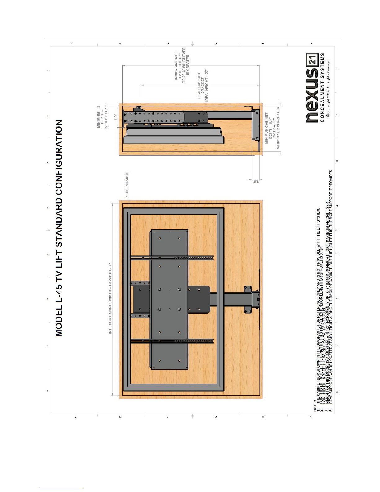
Space requirements for the L-45 Lift System are as follows:
Depth = TV Depth + 5.9”, or 9.3”, whichever is greater.
Height = TV Height +“2, or a minimum of 29.4”, whichever is greater.
Width = TV Width + 2”.
IMPORTANT NOTE: The TV must be mounted as high up as possible inside the cabinet, so that when the Lift is in the fully “DOWN” position
(fully retracted), the top of the TV will be just underneath the lid of the cabinet.
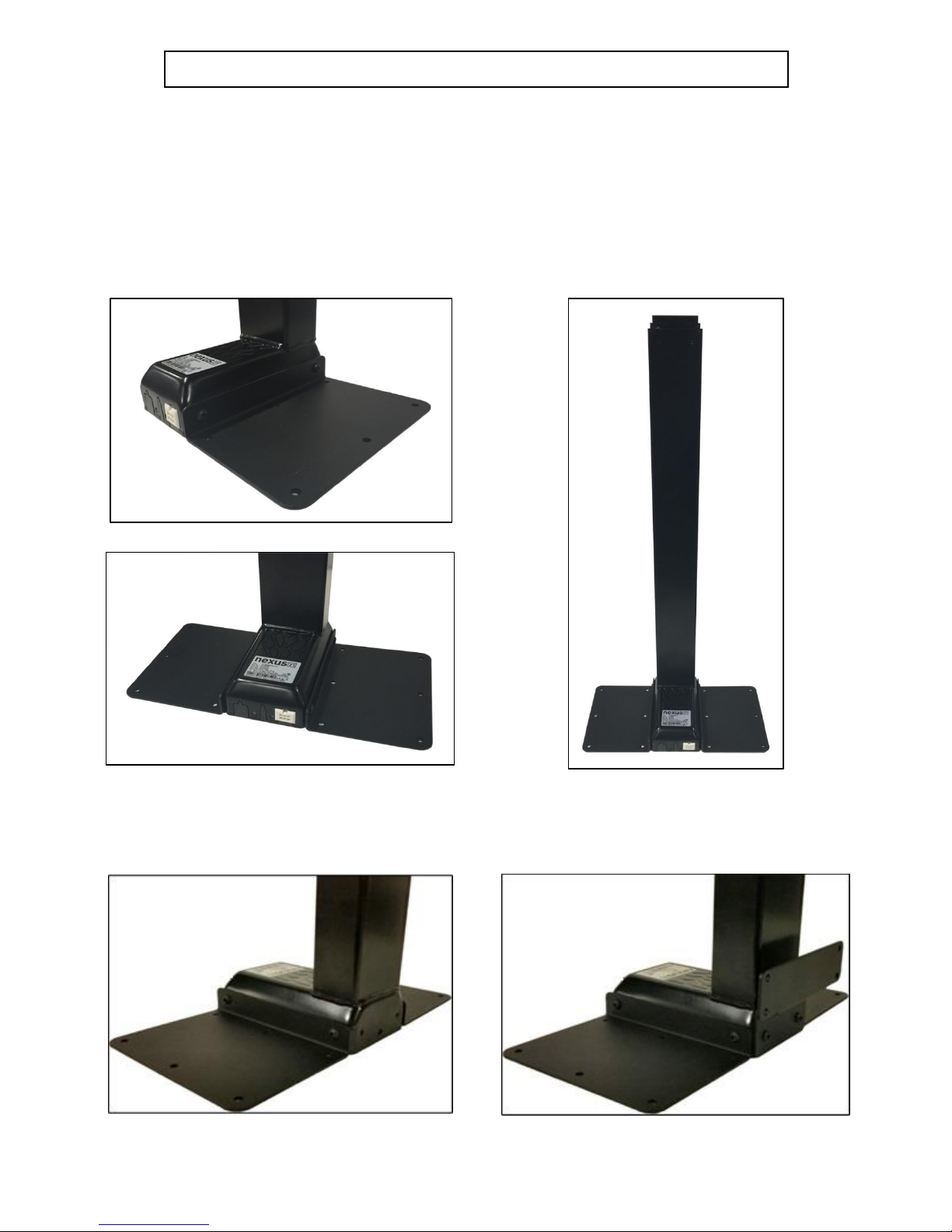
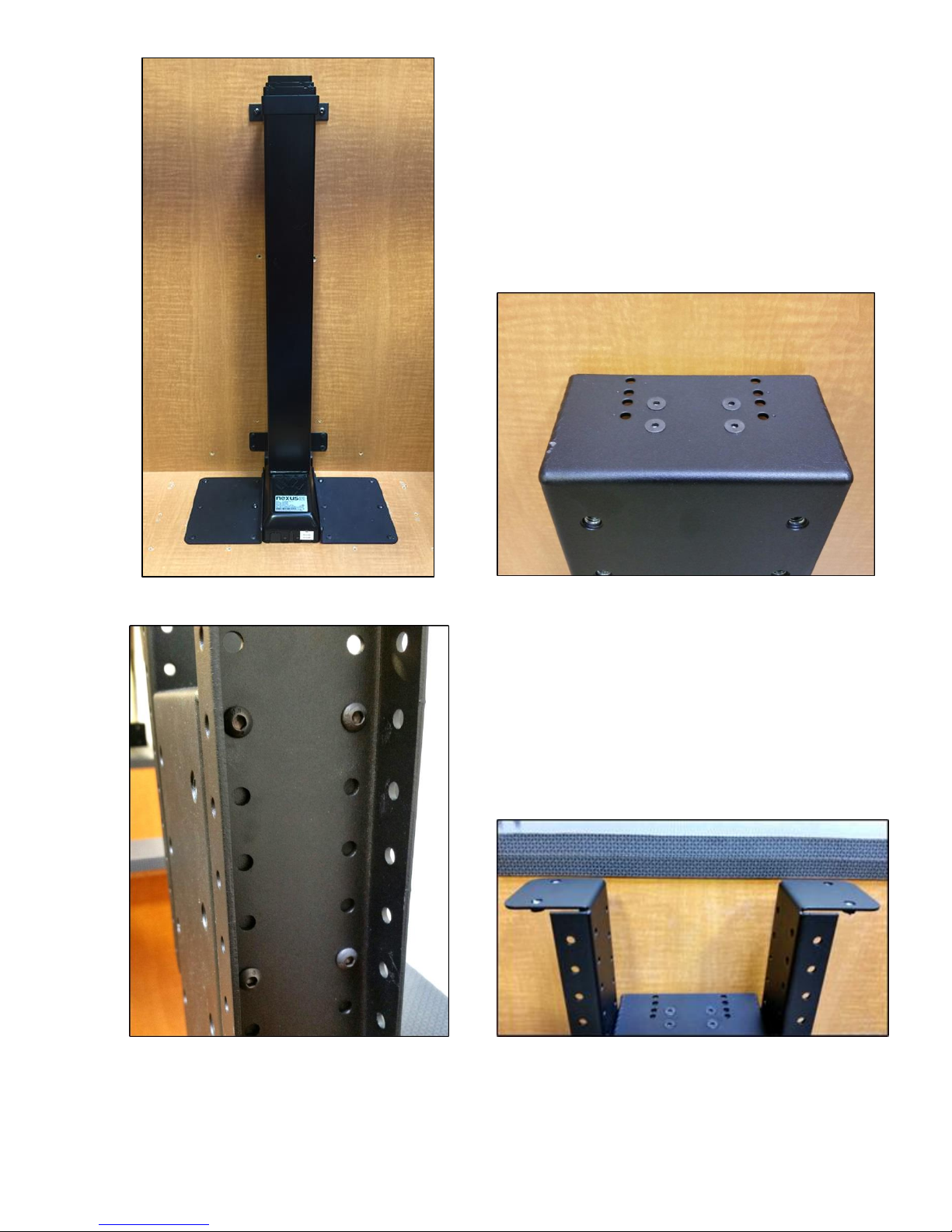
Lift System height and mounting position:
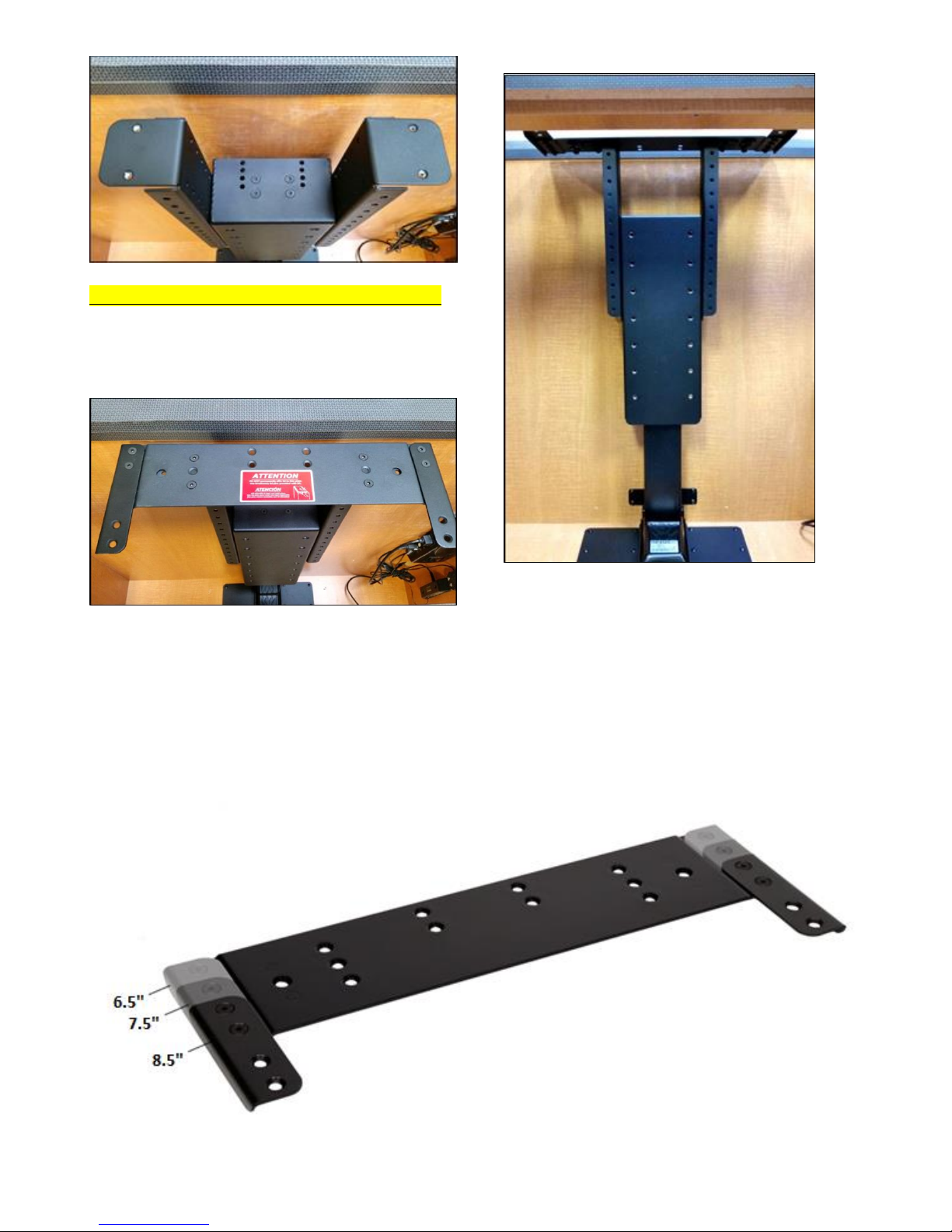
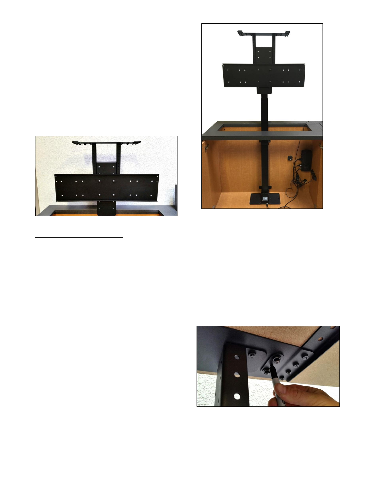
The Top Support Brackets (Part #11) allow you to adjust the installation height of the Lift up to 8” (in ½” increments) to fit
your cabinet height. When fully assembled, the HEIGHT of the Lift will be a minimum of 29.3” (configured for “floating
top”) or 29.5” (configured for “hinged top”) and a maximum of 37.3”(floating top) or 37.5” (hinged-top) with the Top
Support Brackets in the highest position. If the inside height of your cabinet is taller than this, you will need to mount the
Lift higher up inside the cabinet.
About the Cabinet Lid (Cabinet Top)
SAFETY NOTICE:
WARNING! YOU MUST NOT DIRECTLY SCREW THE CABINET LID (TOP) TO THE LIFT SYSTEM!! THIS CREATES HAZARDOUS
“PINCH POINTS” AND MAY AFFECT THE OPERATION OF THE LIFT OR CAUSE DAMAGE TO THE CABINET TOP.
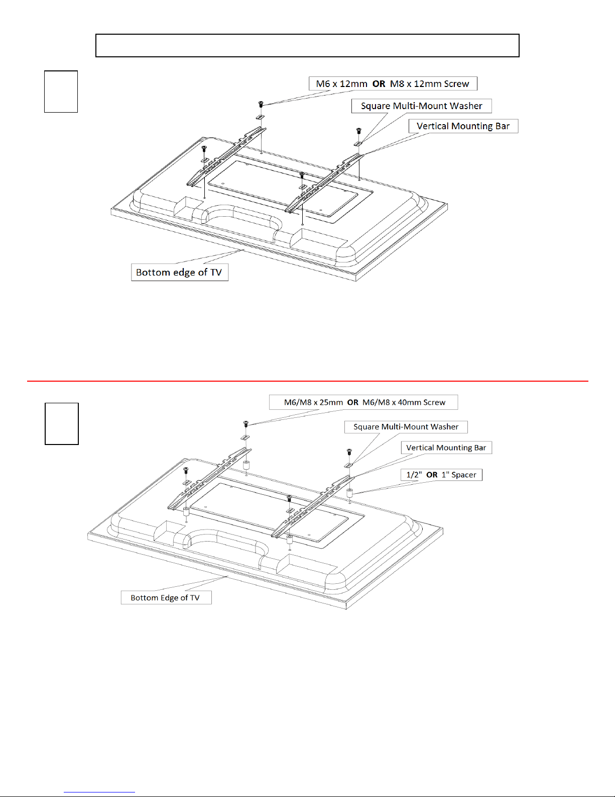
For floating lids, DO NOT USE SCREWS to attach the lid to the Lift System. Instead, use the “Threaded Taper Pins”. This
will keep the lid firmly in place, but will also allow it to separate from the lift system if anything (like a finger) gets in the way when
the TV lowers.
Which Lid Style Will You Use? (There are 3 Different Styles)
Floating Lid (Floating Top) –The whole top of the cabinet sits on top of the Lift System and raises/lowers with the TV.
This is the standard Installation method, using the Top Plate (part #8) and Threaded Taper Pins.
Cut-Out Floating Lid (Top) –You will “cut out” part of your cabinet top, customizing it to the size of your TV. That cut-out
lid then sits on top of the Lift System and raises/lowers with the TV. This method uses the Top Plate (part #8) and
Threaded Taper Pins, but you must set up a “catch” for the cut-out lid so that when the TV lowers, the lid stops level with
the rest of your cabinet top (like a manhole cover).
Hinged-Lid (Hinged-Top) –The top is hinged at the back of the cabinet, behind the TV. It is pushed open by the motion of
the Lift System when the lift travels up, and closes by gravity when the lift travels down. This type of installation does
NOT use the Top Plate or the Tapered Guide Pins, but requires use of the optional Nexus 21 “Hinged-Top Guides”
(purchased separately).
IMPORTANT NOTE: For hinged-top installations, the pivot point of the hinge must be at least 2” behind the back of the Lift
Column. This may require up to one inch of extra depth inside the cabinet.
TIP: The actual HINGES are part of your cabinet and are not provided with the Lift System.

7
You Are Ready to Begin
Please perform the following steps, in order:
Step 1: Inventory the Parts List. Carefully inspect all items, making sure you have everything in the Parts List
on page 1. Be sure to open the Nexus 21 TV Mount carton that includes parts #6, #9 and #13.
Step 2: Attach both Base Plates to the bottom of the Lift Column. Using (4) 6mm x 12mm Button Head
Machine Screws (BHMS), attach (1) Base Plate to each side of the base of the lift column (two screws per side).
Do Not Over Tighten.
Step 3: Attach the Lower Support Bracket. Using (2) 6mm x 12mm Button Head Machine Screws (BHMS)
attach the Lower Support Bracket to the rear of the base of the lift column. Do Not Over Tighten.

8
Step 4a: Attach the Upper Support Bracket. Slide the Upper Support Bracket around the outer profile. Make
sure the Upper Support Bracket sits just above the Nexus 21 label for optimal support.
Step 4b: Attaching the Upper Support Bracket Base (Part #5). Using (2) 6mm x 12mm Button Head Machine
Screws (BHMS) attach the Upper Support Bracket Base to the Upper Support Bracket. Make sure to hold the
Upper Support Bracket Base firmly against lift column while tightening the screws, to ensure there is no lateral
movement.

9
Step 5a: Place the assembled mechanism in the cabinet.
At this point ensure the lift is centered horizontally.
Step 5b: Using (4) #10 x 3/4” THWS mount the Step 5c: Using (2) #10 x ¾” THWS attach
Lower Support Bracket to the back wall of the the Upper Support Bracket to the back wall of
cabinet. the cabinet.

10
Step 6: Using (12) #10 x ¾” THWS attach
both Base Plates to the base of the cabinet.
NOTE: The lift does not have a lower limit.
If the Cabinet is 8” taller than the lift column,
the lift may need to be blocked up.
Step 7: Mount the Control Box and controls to the wall at a nearby accessible location: Using (2) #10 x 1 ¾”
FHWS mount the Control Box to the wall. Using (2) #8 x ¾” FHWS mount the Wired Back Up Switch. If you
ordered IR Controls, then you will use (2) #8 x ¾” FHWS to mount the IR Receiver. If you ordered RF Controls,
then you will use (2) #6 x ¾” FHWS to mount the RF Receiver.
Step 8: Connect the cables for IR Controls as noted on the diagram on the following page, or on page 12 for
RF Controls. Ensure that the motor cable is connected to port #1. The lift will not operate if motor the cable
is connected to ports #2 or #3.

11
IF YOU HAVE IR CONTROLS, USE THIS DIAGRAM (for RF Controls, see the following page)
Once you have connected the controls, test the Lift Column as follows:
First, you need to “initialize” the Lift System. If you have already raised the Lift Column, lower it again, since this step must be
performed in the “down” position. Find the Wired Backup Switch, which has two triangle-shaped buttons - an UP (with raised dot) and
a DOWN. Press the DOWN button and HOLD IT DOWN for approximately 5 seconds. You should see a slight movement in the Lift
Column. If you do not see the movement, release the Down button, and repeat the process - press and hold the Down button again for
5 seconds. Once you have seen the slight movement, the Lift System is now functional. Test it by pressing the Up button (no need to
hold the Up button) and the lift will go up. You may let it go to the top, or stop it at any time by pressing the Down button.

12
IF YOU HAVE RF CONTROLS, USE THIS DIAGRAM (for IR Controls, see the previous page)
Once you have connected the controls, test the Lift Column as follows:
First, you need to “initialize” the Lift System. If you have already raised the Lift Column, lower it again, since this step must be
performed in the “down” position. Find the Wired Backup Switch, which has two triangle-shaped buttons - an UP (with raised dot) and
a DOWN. Press the DOWN button and HOLD IT DOWN for approximately 5 seconds. You should see a slight movement in the Lift
Column. If you do not see the movement, release the Down button, and repeat the process - press and hold the Down button again for
5 seconds. Once you have seen the slight movement, the Lift System is now functional. Test it by pressing the Up button (no need to
hold the Up button) and the lift will go up. You may let it go to the top, or stop it at any time by pressing the Down button.

13
Step 9: Mount the Screen Support to the lift column.
Using (4) 6mm x 16mm FHMS attach the Screen
Support to the top of the lift column, using the four
innermost holes. You may extend the lift at this time
to make the install of the Screen Support Bracket
easier.
Step 10: Attach Top Support Brackets to each
side of the Screen Support Bracket. Using (8)
6mm x 12mm BHMS attach the Top Support
Brackets to the sides of the Screen Support
Bracket (4 Screws per side). Make sure the
Top Support Brackets are no more than ¾”
from the bottom side of the lid catches, when
the lift is fully retracted.
Step 11: Attach the Top Plate to the Top Support Brackets. Using (4) 6mm x 16mm FHMS attach the Top Plate
to the Top Support Brackets. The Top Plate has adjustable wings, to allow more support for larger lids.

14
NOTE: Do not bolt/screw the Lid to the Top Plate. Use
the provided Tapered Pins to attach the Lid to the lift
system. The Tapered Pins allow the lid to lift away
when there is an obstruction. See pages 17 and 18
for details.
The Top Plate is a 5-part plate (one Main Plate, two Extensions and two Fine-tuning Plates) that allows you to
adjust the depth and position of the plate relative to the Threaded Tapered Pins (Steps 22-27). The Top Plate
comes pre-assembled in a semi-retracted configuration. If you need to expand the depth of the plate to
accommodate a deeper cabinet lid, remove the flat head machine screws from the Extensions, move them to
the depth you need, and re-insert the machine screws. Fully retracted, the Top Plate has a depth of 6 ½”, and
can be adjusted to 7 ½” and 8 ½” with the Extensions on either end of the plate. (See Photo Below)

15
Step 12: Attach the Screen Back Plate to the Screen
Support Bracket. Raise the lift to fully expose the Screen
Support Bracket. Using (4) 3/8 –16 x ¾” BHMS attach the
Screen Back Plate to the Screen Support Bracket. To
determine which set of holes to use, measure the upper
bolt hole on the back of the TV to the top of the TV, this
measurement should be relatively the same from the top
of the Screen Support Bracket to the bottom of the Top
Plate.
NOTE: The bent tabs on the Screen Back Plate indicate
the top of the plate.
Step 13:
How to Install the Tapered Pins:
You will be screwing the Tapered Pins into the UNDERSIDE of your cabinet lid, and they will hang down and
drop into the two holes in the Top Plate (Part #8).
Step 13: Before installing the Tapered Pins, position the Cabinet Lid. With the TV and the Lift System in the
fully DOWN position, set the Cabinet Lid in place. It will not be attached at this point, so move it around on the
Top Plate, making sure it fits centered in the cabinet opening.
Step 14:Run the Lift System up and down with the Cabinet Lid sitting on top, but not attached. Without
bumping the Cabinet Lid out of place, use the Remote Control Handset to send the Lift System up and down.
Make sure that when the Lift comes down, the Cabinet Lid drops into the proper position relative to your
cabinet opening.
NOTE: You may want to temporally tape your lid, to
prevent the lid from shifting.
Step 15: Mark the spots for the Tapered Pins. Again,
without bumping the Cabinet Lid out of place, run the
Lift System all the way UP, with the Cabinet Lid sitting
on top. Look at the UNDERSIDE of the Top Plate, find
the two holes, and use a felt-tip pen or a pencil to mark
the position of the holes on the underside surface of the
Cabinet Lid.
NOTE: Make sure the nuts on the bottom side of the Top Plate are hand tight and centered before you mark
your lid.

16
Tapered Pins
Step 16: Remove Cabinet Lid and drill two holes in the marked positions. Use a 7/32” drill bit to drill two
holes, ½” deep, in the underside of the Cabinet Top where you have marked.
Step 17: Using a Phillips head screw
driver (not provided) screw each
Tapered Pin into the holes drilled in
step 16.
Step 18: Place the Cabinet Lid onto the Lift System. Align the Tapered Pins with the 2 holes in the Top Plate
and put the Lid on. Tighten the nuts on the underside of the hole where the Tapered Pins pass through the
Top Plate.
NOTE: You will have a ¼” tolerance (in all directions) for
the placement of the Tapered Pins into your cabinet lid.
There are a set of nuts on the underside of the Top Plate that allow you to adjust the position of the hole that
the Tapered Pins will pass through to secure the cabinet lid to the Top Plate. If you happen to position the
Tapered Pins a few millimeters off from your intended position, you can still make adjustments to fit properly.

17
Installing the Tapered Pins in the Floating Lid
What Are the Tapered Pins, and Why Use Them?
The two 1½” x ¼” Steel Threaded Tapered Pins are used IN PLACE OF SCREWS to hold your cabinet top (lid) in place on the
Lift System Top Plate (Part #8). The Tapered Pins will keep your lid firmly in place, but will also allow it to separate from
the lift system if anything (like a finger) gets in the way when the TV lowers. See Safety Notice above. Please do NOT use
screws with your cabinet lid.
Before You Install the Tapered Pins, Here is a Reminder of the Two Types of Floating Lids (Floating Tops):
Floating Lid (Floating Top) –The whole top of the cabinet sits on top of the Lift System and raises/lowers with the TV.
Cut-Out Floating Lid (Top) –This option assumes that you have “cut out” part of your cabinet top, customizing it to the
size of your TV. That cut-out lid then sits on the Top Plate of the Lift System, held in place by the Taper Pins, and
raises/lowers with the TV. You must set up a “catch” for the Cut-Out Lid so that when the TV lowers, the Lid stops level
with the rest of your cabinet top (like a manhole cover), and the Lift System continues down a little further into the
cabinet (no more than ¼” to ½”). In this way, when the Lift System is fully retracted, the Cut-Out Lid will always be level,
and the Top Plate of the Lift System will always be positioned just below the Lid. Since the Lid and the Top Plate are
slightly separated from one another, but still very close, the Taper Pins (which are 1½” long) will still be hanging down
through the holes in the Top Plate so when the Lift System moves, everything is properly aligned and the Lid rides
smoothly up and down.

18
Step 19: Attach the Vertical Mounting Bars
to the TV. Before you begin, hand thread
screws (found in bag labeled “TV Mounting
Screws/Spacers”) into the threaded inserts
on the back of your TV to determine the
correct screw diameter (M6 or M8). The
length of the screw required will depend on
whether the TV has a flat/unobstructed or
irregular/obstructed back. Follow diagram
“A” for TV’s with flat/unobstructed back.
Use diagram “B” for TV’s with irregular/
obstructed back. The diagrams can be found
on the following page.
Step 20: Mount the TV (with the Vertical Mounting Bars attached) to the Screen Back Plate. Each Vertical
Mounting Bar has “hooks” on either end that allow the bars to “hang” on the Screen Back Plate. Lift the TV
onto the Screen Back Plate. Center the TV. Be sure that both the upper and lower set of “hooks” fully engages
with the Screen Back Plate.
Step 21a: Insert the Screen Locks into both Vertical
Mounting Bars. The Screen Locks will be placed into the
lower “hook” that is just below the Screen Back Plate.
Step 21b: Using a Phillips head screwdriver, tighten both
Screen Lock screws into the underside of the Screen Back
Plate. This will lock your TV onto the TV Lift. You have now
successfully attached your TV.
Step 22: Do a final wire management check. Test operate the Lift and be sure that all wires are clear of the
Lift so they do not get “hung up” when the TV is moving either up or down.
Congratulations your L-45 Lift System is now completed!

19
Mounting the TV to the Lift
Supplemental Page A: Installation Dimensions
Irregular/Obstructed Back
Flat/Unobstructed Back
A
B
Diagram “A” installation procedure:
1) Place the flat screen TV face down on a protected surface.
2) Position the Vertical Mounting Bars equidistant from the bottom and top of the TV, with the slots facing toward the top of
the TV.
3) Using the four (4) Square Multi-Mount washers and the TV mounting screws selected from the bag, attach and tighten the
hardware. DO NOT OVERTIGTHEN HARDWARE. DAMAGE TO TV MAY RESULT.
Diagram “B”installation procedure:
1) Place the flat screen TV face down on a protected surface.
2) Position the Vertical Mounting Bars equidistant from the bottom and top of the TV, with the slots facing toward the top of
the TV.
3) Using the four (4) spacers needed, (4) Square Multi-Mount washers and the TV mounting screws selected from the bag,
attach and tighten the hardware. The hardware will be used in this order (as shown in the diagram above): TV, Spacers,
Vertical Mounting Bars, Square Multi-Mount Washers, TV Mounting Screws.
DO NOT OVERTIGTHEN HARDWARE. DAMAGE TO TV MAY RESULT.

20
Table of contents
Other Nexus 21 Lifting System manuals

Nexus 21
Nexus 21 CL-65e User manual

Nexus 21
Nexus 21 E-550 User manual

Nexus 21
Nexus 21 CL-65e User manual

Nexus 21
Nexus 21 L-90 User manual

Nexus 21
Nexus 21 L-77i User manual

Nexus 21
Nexus 21 AL-125 User manual

Nexus 21
Nexus 21 CL-65 Series User manual

Nexus 21
Nexus 21 DL-45b User manual

Nexus 21
Nexus 21 L-75ix User manual

Nexus 21
Nexus 21 XL-85s User manual
Popular Lifting System manuals by other brands

Bend-Pak
Bend-Pak HD-973P Installation and operation manual

SmartMetals
SmartMetals 062.7225B product manual

Bend-Pak
Bend-Pak HD-9ST Installation and operation manual

OEM Tools
OEM Tools 24859 Operating instructions and parts manual

Bend-Pak
Bend-Pak HDS-40 Service manual

Troy-Bilt
Troy-Bilt T 90010 user manual