Nexus 21 L-27i User manual

TV Lift System Model L-27i
Installation Instructions

2
Contact: [email protected]
Toll Free: (866) 500-5438
Phone: (480) 951-6885
Fax: (480) 951-6879
Revised: 6/23/15
Below is a parts list describing all of the items included with the Model L-27i Lift System. You may also
wish to refer to the dimensional diagram shown on Supplemental Page A for minimum installation
dimensions (found on page 21).
IMPORTANT DETAILS ABOUT THIS LIFT MODEL:
This Lift Model is for use in an inverted orientation (e.g. lowering a TV from an upper kitchen
cabinet) and cannot be used as a “pop-up” TV Lift. If your project calls for a pop-up lift (to raise your
TV up from below), please call Nexus 21 customer Service, at (866) 500-5438.
Before beginning assembly and installation, please make sure that you have all items included on the
list. If any parts are missing or damaged, please contact Nexus 21. Our contact information is shown
at the top of this page.
Parts List
1. Lift Column 2. Base Mount 3. Bayonet Bracket
(22” x 4”) (2 ¾” x 6”) (8” x 5 ¼”)
4. Screen Support 5. Lid Plate 6. Screen Back Plate
(6 ¼” x 18”) (18” x 4 ½” – 6 ½”)(24” x 9”)
7. Vertical Mounting Bars 8. Control Box 9. Lid Support Brackets
(1” x 16 ¾”) (10 ½” x 3 ¾” x 1 ½”) (14” x 2 ¾”)
NOTE: Items 6 & 7 are packaged together in the “Nexus 21 Standard TV Mount” package.

3
Cables
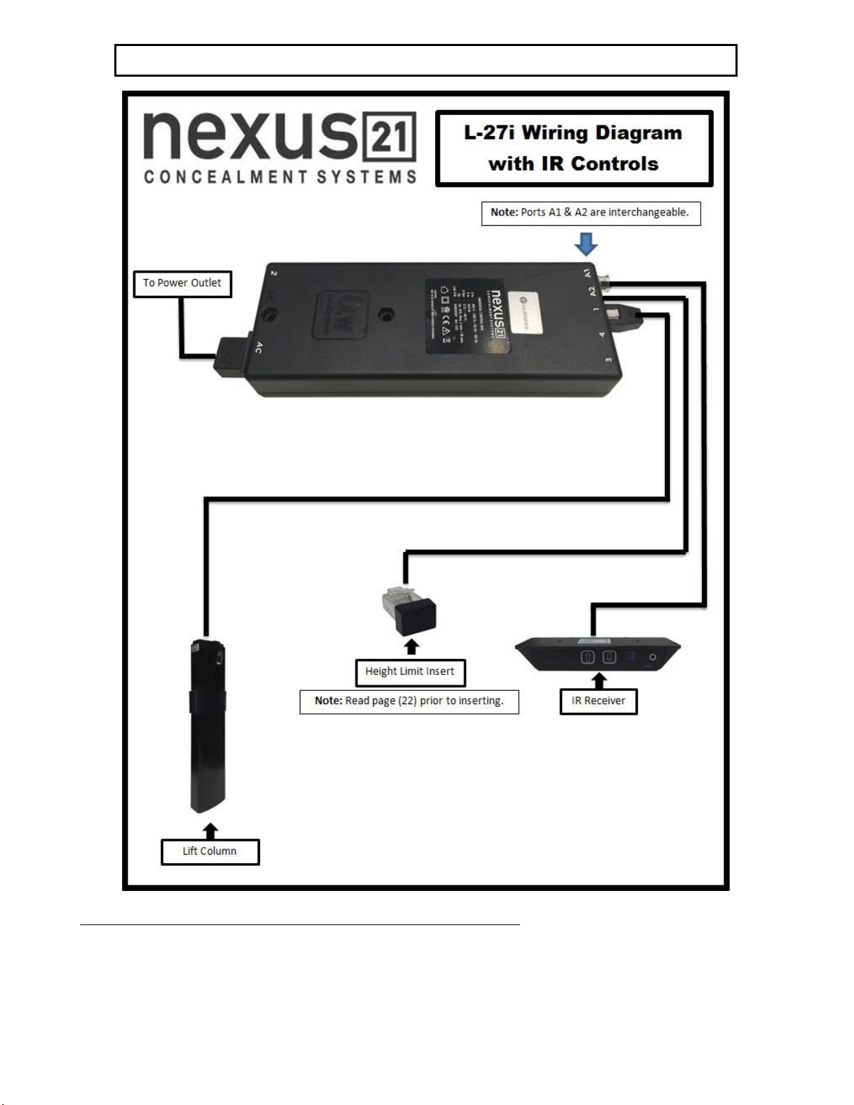
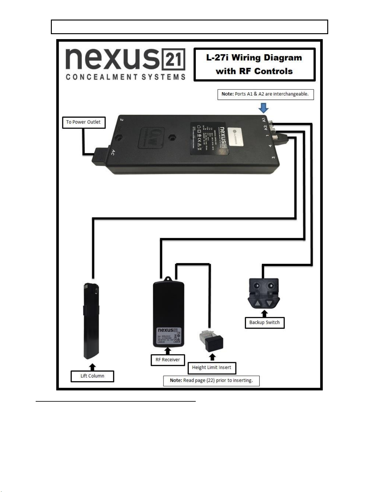
Motor Cable –Black cable with white, six-pin plugs. Use this cable to connect the Lift Column to the Control Box
(using port #1 on the Control Box). Six feet long.
Power Cable –Connects Control Box to power outlet. Three feet long.
RF Cable (only present if you ordered the RF version of the Lift System) –Use to connect the RF Receiver to the
Control Box. Ends have telephone-style connectors. One foot long.
TIP: It is recommended to install a surge protector (not included) inside your cabinet to plug in the Lift System,
Control Box, TV and any other components in the cabinet.
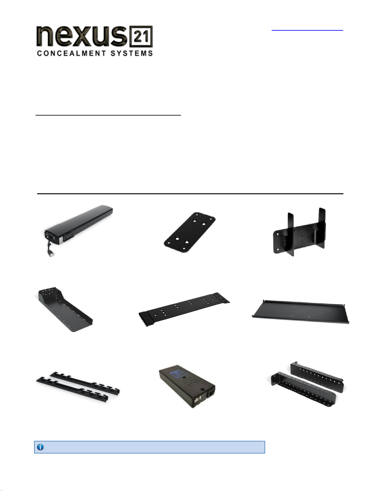
Hardware
10. One (1) –Assorted Bag of TV Mounting Screws
11. Six (6) -- 6mm x 12mm Button Head Machine Screws
12. Two (2) -- Screen Locks (Located in box with Part #6 & 7)
13. Four (4) -- 3/8”-16 x ¾” Button Head Machine Screws
14. Two (2) -- #10 x 1 ¾” Flat Head Wood Screws
15. Four (4) -- #8 x ¾” Flat Head Wood Screws
16. Two (2) -- #4 x 1” Pan Head Wood Screws
17. Four (4) -- 6mm x 40mm Flat Head Machine Screws
18. Four (4) -- 6mm x 12mm Flat Head Machine Screws
19. Eight (8) -- #10 x ¾” Truss Head Wood Screws
20. Four (4) -- 6mm x 16mm Button Head Machine Screws
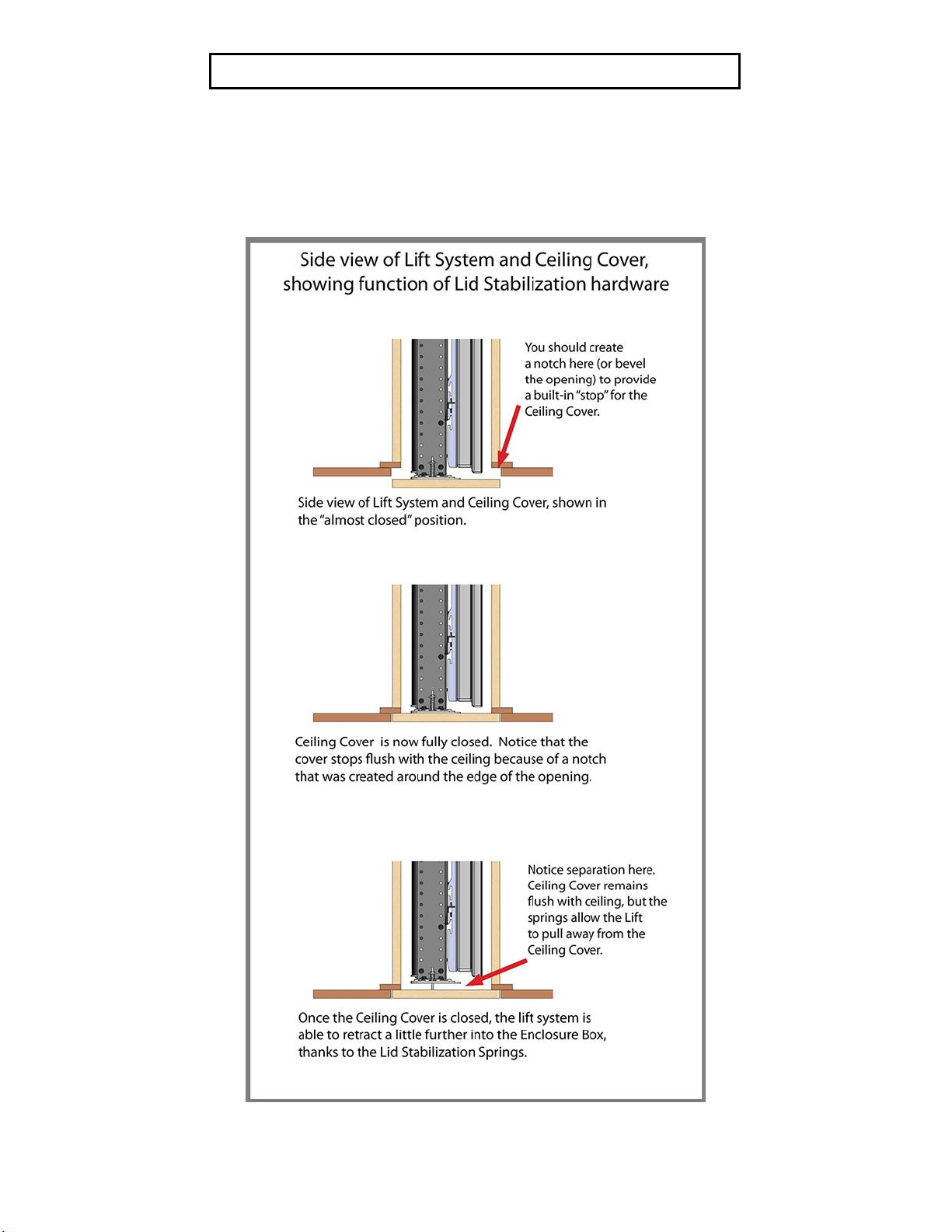
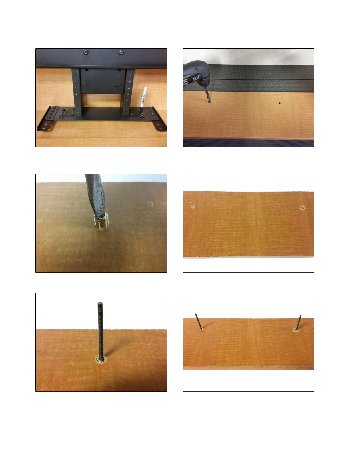
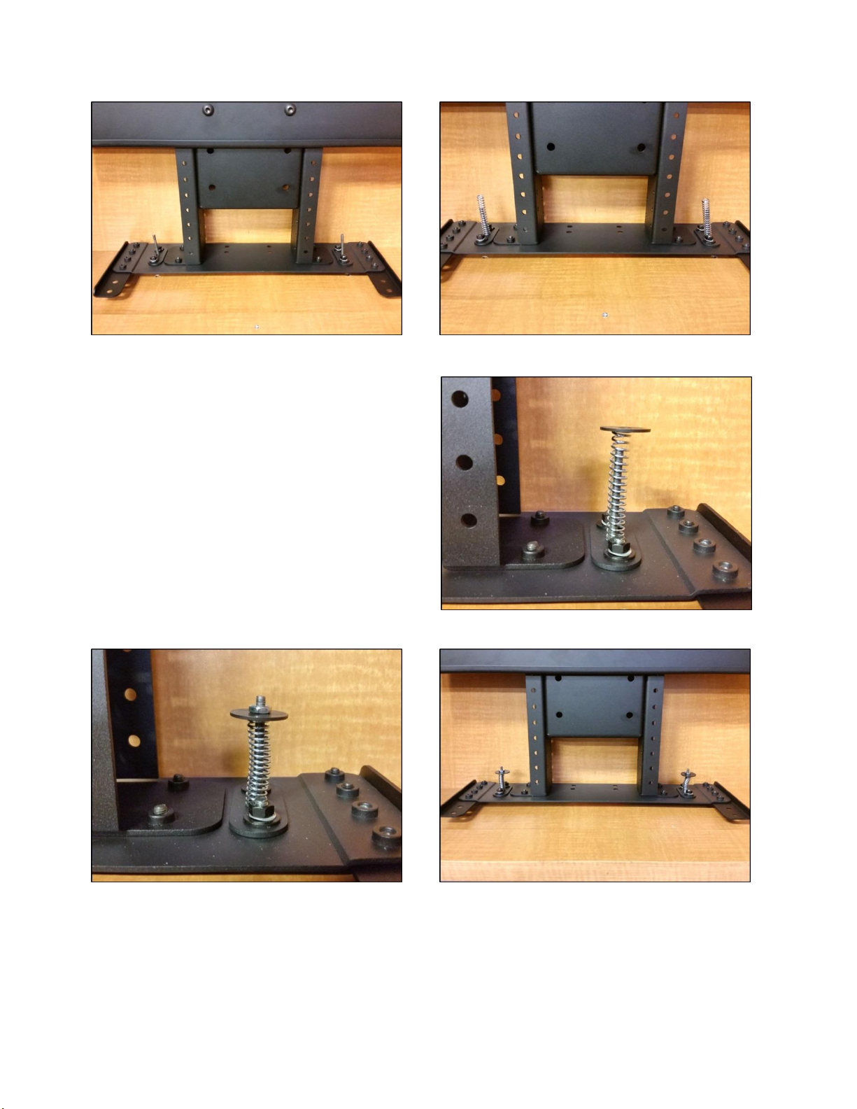
Contents of hardware pack that is labeled “Lid Stabilization Pack”
21. Two (2) -- 10-32 Nut
22.Two (2) -- 10-32 x 3” Threaded Studs
23 Two (2) -- Lid Stabilization Springs
24. Two (2) -- Brass Threaded Inserts
25. Two (2) –Flat Washers
Other items that are included, but not shown in Parts View diagram on “Supplemental Page A” (at the end of this
document):
RF Controls or IR Controls (see explanation on page 6)
Two (2) -- Allen Wrench –4mm and 7/32”
One (1) -- “Snakeskin” Wire Management Sleeve – 3 feet long
Two (4) -- Velcro end Ties, for use with Wire Management Snakeskin
Two (4) -- Plastic Ties, also for use with Wire Management Snakeskin
Four (4) -- Wire Clips
One (1) -- Small Cable Re-coiler
Four (4) -- Square Multi-Mount Washers
Wire Management
The Lift System has no exposed gears or moving parts that can damage your
wires, so wire management is simple. We have included a three-foot long
“SNAKESKIN” sleeve, which is a state-of-the-art wire bundling and
protection system (the sleeve can be cut shorter if you wish). The System
also includes 4 Velcro end ties, 4 plastic ties and a small cable re-coiler. Use
the Velcro ties at the ends of the SNAKESKIN, to close the ends of the sleeve
and to keep the wires together inside it. Use the plastic ties to fasten the
cable bundle in a fixed position, so it moves up and down with the lift. Use
the small cable re-coiler to assist pulling the cables back into your enclosure.

4
SAFETY INFORMATION
SEVERE PERSONAL INJURY AND PROPERTY DAMAGE CAN RESULT FROM IMPROPER INSTALLATION
OR ASSEMBLY. READ THE FOLLOWING WARNINGS BEFORE BEGINNING:
WARNINGS:
1. Do not use this product for any application other than those specified by Nexus 21.
2. Do not exceed the weight capacity. This can result in serious personal injury or damage to the equipment. It is the installer’s
responsibility to ensure that the total combined weight of all attached components does not exceed that of the maximum
figure stated.
3. Follow all technical specifications and instructions during the installation.
4. Only use attachments/accessories specified by the manufacturer.
5. Close supervision is necessary when this system is being used by, or near, children, or disabled persons.
6. It is the responsibility of the installer to warn all potential users of the dangers of interfering with the mechanism during
operation.
7. Read all technical instructions fully before installation and use. It is the installer’s responsibility to ensure that all
documentation is passed on the users and read fully before operation.
8. Failure to provide adequate structural strengthening, prior to installation can result in serious personal injury or damage to
the equipment. It is the installer’s responsibility to ensure the structure to which the Lift System is affixed can support four
times the weight of the system.
9. Risk of electric shock. Do not attempt to open the Control Box.
10. To reduce risk of fire or electric shock, do not expose parts to rain or other liquids.
11. Protect the power cord from being walked on or pinched.
12. Keep all documentation.
13. Heed all warnings.
14. Clean only with a dry cloth.
15. Refer all service questions to Nexus 21 if the system does not operate normally.
Nexus 21 disclaims any liability for modifications, improper installations, or installations over the specified weight range. Nexus 21 will not be liable for
any damages arising out of the use of, or inability to use, Nexus 21 products. Nexus 21 bears no responsibility for incidental or consequential damages.
This includes, but is not limited to, any labor charges for the servicing of Nexus 21 products performed by anyone other than Nexus 21.
Nexus 21 intends to make this and all documentation as accurate as possible. However, Nexus 21 makes no claim that the information contained herein
covers all details, conditions or variations, nor does it provide for every possible contingency in connection with the installation or use of this product. The
information contained in this document is subject to change without prior notice or obligation of any kind. Nexus 21 makes no representation of
warranty, expressed or implied, regarding the information contained herein. Nexus 21 assumes no responsibility for accuracy, completeness or
sufficiency of the information contained in this document.
ENCLOSURE LID HAZARD
TV HAZARD
CAUTION: Avoid contact with the TV and Lift System during
operation. Use with caution.
CAUTION: The enclosure lid must be installed as described in
the instructions, using the Lid Stabilization hardware. Installing
the lid in any other fashion will create hazardous pinch points
that can cause serious personal injury.

5
Types of Controls for Nexus 21 Lift Systems
All Nexus 21 Lift Systems come standard with a wireless remote control and receiver. We offer a choice of two different
type of remotes: IR and RF (both of which are explained in detail below). Our standard control type is RF, so unless you
specifically requested the IR version when you made your purchase, you probably received the RF controls with this Lift
System. The method of installation for each type of remote control is slightly different, so you should now identify which
type of remote you have by reading below, and then follow the instructions for that type of remote.
NOTE: If you will be using the Lift with a home control system (like the ones made by companies such as Crestron or
Control 4) the most common form of control is to WIRE IT DIRECTLY to the relays of your home control system. This
direct-wire method is called Integration by Contact Closure, and is accomplished by using the Backup Control Switch
(Height Limit Switch) that was supplied with the Lift System to connect the Lift to the control unit from your home control
system.
Before You Begin the Installation: Identify Your Control Type
IR (Infrared) –This control option allows you to utilize a 3rd party universal style remote control to raise and lower the
TV Lift. Your universal remote will “learn” the IR codes from the provided IR Handset, which will enable you to control the
lift. The universal remote will then communicate with the “eye” located on the IR Receiver via your 3rd party emitter (or
flasher). Instructions for mounting the IR controls are on page 14. Instructions for setting the TV Lift’s travel limit are on
Supplemental Page B.
NOTE: If you are NOT planning on using a 3rd party Universal Remote, switch to the RF setup. (There is no charge for swapping)
These are the parts included with IR controls:
Contact Closure Hardware IR Receiver IR Handset Height Limit Insert
RF (Radio Frequency) - This system utilizes a wireless remote control handset that sends a radio signal to the RF
Receiver. The radio signal can go through cabinet walls and does not require line-of-sight. Instructions for mounting the
RF controls are on page 15. Instructions for setting the Lift System travel limit are on Supplemental Page B.
TIP: Planning to integrate the TV Lift with your UNIVERSAL REMOTE CONTROL? The RF version of the Nexus 21 controls won’t do
it. Switch to IR.
These are the parts included with RF controls:
Backup Switch RF Receiver RF Handset Height Limit Insert
Integration by Contact Closure –To direct-wire the TV Lift controls to a home control system (Crestron, Control 4,
AMX, etc.) you will use the Back-up Control Switch (Height Limit Switch). You won’t use any Nexus 21 receiver or handset
for this type of control because you will use the handset or control pad that comes with your home control system.
Instructions for setting up the System using Contact Closure are on “Supplemental Page C”.

6
NOTE: The Lid Cover is not provided with the Lift System, as it is part of your cabinetry
What is the Lid Cover? The Lid Cover is the piece of material that you choose to have “float” just below the TV.
Typically, this material is made of wood and is not provided with the lift system. When the TV lift fully retracts, the Lid
Cover will conceal the hole that is required for the system to drop-down through the cabinet and into view.
SAFETY NOTICE:
WARNING! YOU MUST NOT DIRECTLY SCREW THE CABINET LID COVER TO THE LIFT SYSTEM!! THIS CREATES HAZARDOUS
“PINCH POINTS” AND MAY AFFECT THE OPERATION OF THE LIFT OR CAUSE DAMAGE TO THE CABINET LID.
DO NOT USE SCREWS to attach the lid cover to the Lift System. Instead, use the “LID STABILIZATION PACK” (PARTS #22-25). This
will keep the lid firmly in place, but will also allow it to separate enough from the lift system if anything (like a finger) gets in the
way when the TV raises.
How to do the Cut-Out Lid Cover –You will “cut-out” part of your cabinet bottom, customizing it to the size of your TV.
The dimensions for this cut-out are as follows: Width= TV width plus 2”, Depth= TV Depth + 5.5”. That cut-out lid then
attaches to the lid plate of the Lift System and raises/lowers with the TV. This method uses the Lid Plate (part #7) and Lid
Stabilization Pack (parts #22-25), but you must set up a “catch” for the cut-out lid so that when the TV raises, the lid stops
level with the rest of your cabinet bottom (like a manhole cover). This procedure is described later on page 14.
Assembly and Mounting –Things to Think About First
SAFETY NOTICE:
For proper support, the Lift System MUST NOT be attached to any material that is less than ¾” thick. This applies to BOTH the back
and top mounting points.
The Lift Column is ONLY designed and rated for VERTICAL, INVERTED USE. DO NOT MOUNT THIS LIFT SYSTEM UPSIDE DOWN or
SIDEWAYS (HORIZONTALLY, AS IN A LATERAL MOUNT)!
Space requirements for the L-27i Lift System are as follows:
Depth= TV depth PLUS 5.5”
Height = TV height plus 1”or 23.2 minimum.
Width= the inside of the cabinet should be at least 2” wider than your TV.
IMPORTANT NOTE: The Lift System must be mounted as low as possible inside the cabinet, so that when the Lift is in the fully “UP” position
(fully retracted), the bottom of the TV will be just above the lid of the cabinet.
Lift System height and mounting position:
When fully assembled, the HEIGHT of the Lift will be 23.2”.
TIP: If you need to mount the lift lower inside the cabinet, you can cut a wood block or mount a small shelf inside the cabinet for the top of the
Lift Column (Base Mount) to mount on. Keep in mind that the “Bayonet Bracket” (part #3) will bear most of the weight.
IMPORTANT NOTE: THE LID COVER IS OPTIONAL. Many people prefer to have the TV lower with no lid attached below the
TV. If you are NOT going to be using a lid cover, please skip this section and continue to “Types of Controls” below.
About the Cabinet Lid Cover

7
Assembly and Mounting Instructions –DETAILED STEPS
Preparing the Enclosure Box
BEFORE BEGINNING, PLEASE READ THE SAFETY NOTICE ON THE FIRST PAGE OF THIS DOCUMENT
The Enclosure Box for the TV and Lift System should be constructed of materials no less than ¾” thick. We recommend a
high-grade plywood or combi-core material. The back and top of the enclosure are the parts that must be able to support
the weight of the lift and TV, so particle board materials are not suitable for use in this project.
The Enclosure Box dimensions depend on the size of your TV. Please review the Installation Dimensions Drawing on page
10 before beginning. IF YOU HAVE THE SPACE, WE RECOMMEND INCREASING EACH DIMENSION BY 1” TO MAKE FOR
EASIER INSTALLATION AND SERVICE ACCESS.
The End, Front and Back panels of the Enclosure Box should be attached to the underside of the Top Cover, so that the
Top Cover is resting on top of the four panels. This provides the maximum strength for holding the Lift and TV in its
inverted orientation.
Step 1: Cut the five panels from ¾” plywood. Paint the inside of the panels a dark color before assembly. This will help
camouflage the Enclosure Box after it is installed.
Step 2: Determine where the electrical power will feed into the Enclosure Box. Cut out the appropriate sized opening
near the top of the End Panel nearest the power feed. We recommend using a 110V duplex outlet and conduit that
conform to the building code for your location.
Step 3: Cut out a Control Box Access door in one of the panels, to ensure accessibility of the control box.
a) This will provide convenient access to the electrical connections in the Control Box after installation.
b) Put hinges and a latch (not provided) on the outside of the door so it opens OUT.
c) Re-attach the Access Door to the Back Panel.
Step 4: If a ventilation fan (not provided) is needed (in climates where attic temperatures exceed 110 degrees F), cut
the opening for the fan near the top of the End Panel opposite the electrical feed. This will vent into the attic.

8
Assembly and Mounting Instructions –You Are Ready to Start
Please perform the following steps, in order:
Step 1: Inventory the Parts List. Carefully inspect all items, making sure you have everything shown in the Parts List.
Step 2: Seat the “pigtail” cable properly on the top of the Lift Column. Take the Lift Column (Part #1) and find the end
with the short black cable (this cable is called the “pigtail”). This end will become the BOTTOM of the Lift Column. Before
you begin to assemble the system, you must position the pigtail properly. Look at the bottom edge of the Lift Column.
You will see two square cut-out channels, notched into the steel, one on either side of the pigtail. Choose one of the cut-
outs (it does not matter which one), and seat the pigtail into the cut-out, using the rubber gasket attached to the cable.
IMPORTANT NOTE: IF THE PIGTAIL CABLE IS NOT PROPERLY SEATED, IT MAY BE DAMAGED WHEN YOU ATTACH THE SCREEN SUPPORT
BRACKET (Part #4), CAUSING LOSS OF POWER TO THE LIFT COLUMN.
IMPORTANT NOTE: The pigtail now hangs over one side of the Lift Column. From this point forward, that side will be referred to as the
“Front” of the Lift Column.
BEFORE (pigtail is loose) AFTER (pigtail is properly seated)
Step 3a: Attach the Bayonet Bracket to the Lift Column. Slide the Bayonet Bracket (Part #3) onto the Lift Column (Part
#1). Stand the Lift Column up. Gently slide the Bayonet Bracket into the tapered, welded slots on either side of the Lift
Column (on the opposite side of the pigtail cable).

9
Step 3b: Lightly tap the right and left side of the Bayonet Bracket with a rubber mallet to properly seat the bracket. Turn
the Lift Column around and check to make sure the Bayonet Bracket is level.
Step 4: Place the Base Mount (Part #2) inside of your enclosure against the back wall and the top panel of the enclosure.
Make sure to center the Base Mount from left to right inside the enclosure. Mark the four countersunk holes of the Base
Mount. Using a ¼” drill bit, drill all four marked holes through the top panel of the enclosure.
Step 5: Place the Base Mount (Part #2) on the top side of the top panel of the enclosure. Place (4) 6mm x 40mm FHMS
through the Base Mount.

10
Step 6: Attach the Lift Column to the Base Mount. Place
the Lift Column (Part #1) with the Bayonet Bracket (Part #3)
attached against the back wall of the enclosure. Using the
provided small 4mm Allen Wrench drive the (4) 6mm x
40mm FHMS Screws into the top of the lift column.
NOTE: The end of the Lift Column with the “pig-tail” is the
bottom of the Lift Column.
Step 7: Using a level, make sure the Lift Column is level and parallel with side panels of the enclosure. Using (4) #10 x ¾”
THWS Screws mount the Bayonet Bracket to the back wall of the enclosure.
Step 8: Connect the Motor Cable to the pig-tail of the lift
column.

11
Step 9a: Attach the Screen Back Plate (Part #6) to the Screen Support Bracket (Part #4). Using (4) 3/8-16 x ¾” BHMS
attached the Screen Back Plate to center of the Screen Support Bracket. NOTE: Make sure the bent tabs on the Screen
Back Plate are on the top.
Step 9b: Place two Wire Clips to the inside wall of the
Screen Support Bracket. Place one Wire Clip just below
the upper set of PEM nuts. Place the second Wire Clip
towards the top of the Screen Support Bracket.
Step 10: Attach the Screen Support Bracket (Part #4) to the Lift Column (Part #1). Using (4) 6mm x 16mm BHMS attached
the Screen Support Bracket to the bottom of the Lift Column using the four outer most holes on the Screen Support
Bracket. NOTE: Make sure to run the Motor Cable through the Wire Clips installed in the previous step to ensure proper
cable management of the Motor Cable.

12
Step 11: Attach the Top Support Brackets (Part #9) to the Screen Support Bracket (Part #4) . Using (6) 6mm x 12mm
BHMS (3 screws per side) fasten the Top Support Brackets, so the bottom of the Top Support Brackets are a ½” above the
opening at the bottom of the enclosure.
Step 12: Attach the Lid Plate (Part #5) to the Top Support Brackets (Part #9). Using (4) 6mm x 12mm FHMS Screws attach
the Lid Plate to the Top Support Brackets.

13
Step 13: Mounting the Controls to the Back Panel of the Enclosure: Using (2) #10” x 1 ¾” FHWS attach the Control Box
and (2) #8” x ¾” FHWS for the IR or RF Receiver (Depending on which Controls you ordered) to the back panel of the
enclosure. The RF Receiver or IR Receiver will plug into either RJ45 port on the Control Box. The Motor Cable must plug in
to Port # 1 on the Control Box.
Control Box IR Receiver
Wired Back Up Switch RF Receiver

14
IF YOU HAVE IR CONTROLS, USE THIS DIAGRAM (for RF Controls, see the following page)
Once you have connected the controls, test the Lift Column as follows:
First, you need to “initialize” the Lift System. If you have already lowered the Lift Column, raise it again, since this step must be
performed in the “up” or retracted position. Find the Wired Backup Switch, which has two triangle-shaped buttons - a DOWN (with
raised dot) and an UP. Press the UP button and HOLD IT for approximately 5 seconds. You should see a slight movement in the Lift
Column. If you do not see the movement, release the UP button, and repeat the process - press and hold the UP button again for 5
seconds. Once you have seen the slight movement, the Lift System is now functional. Test it by pressing the DOWN button (no need to
hold the DOWN button) and the lift will lower. You may let it go all the way down, or stop it at any time by pressing the UP button.

15
IF YOU HAVE RF CONTROLS, USE THIS DIAGRAM (for IR Controls, see the previous page)
Once you have connected the controls, test the Lift Column as follows:
First, you need to “initialize” the Lift System. If you have already lowered the Lift Column, raise it again, since this step must be
performed in the “up” or retracted position. Find the Wired Backup Switch, which has two triangle-shaped buttons - a DOWN (with
raised dot) and an UP. Press the UP button and HOLD IT for approximately 5 seconds. You should see a slight movement in the Lift
Column. If you do not see the movement, release the UP button, and repeat the process - press and hold the UP button again for 5
seconds. Once you have seen the slight movement, the Lift System is now functional. Test it by pressing the DOWN button (no need to
hold the DOWN button) and the lift will lower. You may let it go all the way down, or stop it at any time by pressing the UP button.

16
Installing the Lid Stabilization Assembly
The two Lid Stabilization Assemblies (each consisting of parts #21 - 25) are used to hold the Ceiling Cover Cut-out in
proper alignment with ceiling opening. The assemblies are spring loaded so the Ceiling Cut-out will stop level with the
ceiling allowing the Lift to travel an additional 1/8 ”– 1/2” up into the ceiling. You should create a “stop”, or “lip” above
the ceiling, around the edge of the opening, for your Ceiling Cover to pull up against, like an upside-down manhole cover.
This illustration shows how it should work, and details for assembly are shown on the following pages.

17
Step 14a: Hold your lid piece (your ceiling cut-out piece) up to the Lid Plate (part #5), which you have already installed on
the lift. The Lid Plate has 2 holes that are used to attach your lid piece. Mark the position of the holes on your lid piece.
Drill two holes ½” deep using a 3/8” drill bit in the marked positions.
Step 14b: Using a flat head screw driver, drive the Brass Inserts (Part #25) into the ½” deep holes. Make sure to drive the
Brass Inserts into your lid material, so they are flush with the lid material.
Step 15a: Screw the (2) Threaded Studs (Part#23) into each Brass Insert, until they are fully seated.

18
Step 15b: Place the lid material against the bottom side of the Lid Plate; slide the Threaded Studs through the two holes
on the Lid Plate. Slide (2) Lid Stabilization Springs (Part #24) over the Threaded Studs.
Step 15c: Add a 1” Fender Washer to the Threaded Studs
on top of the spring you previously installed. Once washer
is added, fasten a 10-32 Nut (Part #22) to the top of the
Threaded Studs. You will need to compress the spring in
order to screw the nuts down.

19
Mounting the TV to the Lift
Supplemental Page A: Installation Dimensions
Irregular/Obstructed Back
Flat/Unobstructed Back
A
B
Diagram “A” installation procedure:
1) Place the flat screen TV face down on a protected surface.
2) Position the Vertical Mounting Bars equidistant from the bottom and top of the TV, with the slots facing toward the top of
the TV.
3) Using the four (4) Square Multi-Mount washers and the TV mounting screws selected from the bag, attach and tighten the
hardware. DO NOT OVERTIGTHEN HARDWARE. DAMAGE TO TV MAY RESULT.
Diagram “B”installation procedure:
1) Place the flat screen TV face down on a protected surface.
2) Position the Vertical Mounting Bars equidistant from the bottom and top of the TV, with the slots facing toward the top of
the TV.
3) Using the four (4) spacers needed, (4) Square Multi-Mount washers and the TV mounting screws selected from the bag,
attach and tighten the hardware. The hardware will be used in this order (as shown in the diagram above): TV, Spacers,
Vertical Mounting Bars, Square Multi-Mount Washers, TV Mounting Screws.
DO NOT OVERTIGTHEN HARDWARE. DAMAGE TO TV MAY RESULT.

20
Step 16: Attach the Vertical Mounting Bars
to the TV. Before you begin, hand thread
screws found in bag labeled “TV Mounting
Screws/Spacers” into the threaded inserts
on the back of your TV to determine the
correct screw diameter (M6 or M8). The
length of the screw required will depend on
whether the TV has a flat/unobstructed or
irregular/obstructed back. Follow diagram
“A” for TV’s with flat/unobstructed back.
Use diagram “B” for TV’s with irregular/
obstructed back. The diagrams can be found
on the following page.
Step 17: Mount the TV (with the Vertical Mounting Bars attached) to the Screen Back Plate. Each Vertical
Mounting Bar has “hooks” on either end that allow the bars to “hang” on the Screen Back Plate. Lift the TV
onto the Screen Back Plate. Center the TV. Be sure that both the upper and lower set of “hooks” fully engages
with the Screen Back Plate.
Step 18: Insert the Screen Locks into both Vertical Mounting
Bars. The Screen Locks will be placed into the lower “hook”
that is just below the Screen Back Plate.
Step 19: Tighten the Screen Locks. Using a Phillips head
screwdriver, tighten both Screen Lock Screws into the
underside of the Screen Back Plate. This will lock your TV onto
the TV Lift. You have now successfully attached your TV.
Step 20: Attach the Cable Re-coiler to your cables. Mount the provided Cable Re-coiler towards the top of
your enclosure on the same side as the control box. Attach the cable to the bundle of wires that run to the
back of your TV. This will help aid the cables back into the enclosure as the lift fully retracts. Test operate the
lift and be sure that all wires are clear of the lift, so they do not get “hung up” when the TV is moving in either
direction.
Congratulations your L-27i Lift System is now completed!
Table of contents
Other Nexus 21 Lifting System manuals

Nexus 21
Nexus 21 L-90 User manual

Nexus 21
Nexus 21 L-85 User manual

Nexus 21
Nexus 21 AL-125 User manual

Nexus 21
Nexus 21 L-77i User manual

Nexus 21
Nexus 21 CL-65 Series User manual

Nexus 21
Nexus 21 L-23S User manual

Nexus 21
Nexus 21 DL-45b User manual

Nexus 21
Nexus 21 CL-65e User manual

Nexus 21
Nexus 21 L-75ix User manual

Nexus 21
Nexus 21 E-550 User manual
Popular Lifting System manuals by other brands

Bohle
Bohle Veribor BO 600.1G operating instructions

Panasonic
Panasonic Factory Line 20 instruction manual

Reid
Reid PORTA-GANTRY 500 Assembly & operation

Central Hydraulics
Central Hydraulics 94780 Installation, operation and maintenance manual

Rotary
Rotary E Series manual

Fenix
Fenix MEGARA 150 instructions