Models 24012 (E, W, EW, XL, LR, AR)
Installation, Operation and Maintenance
File: 24107 2 Rev. 01.09.01
Installation Procedure
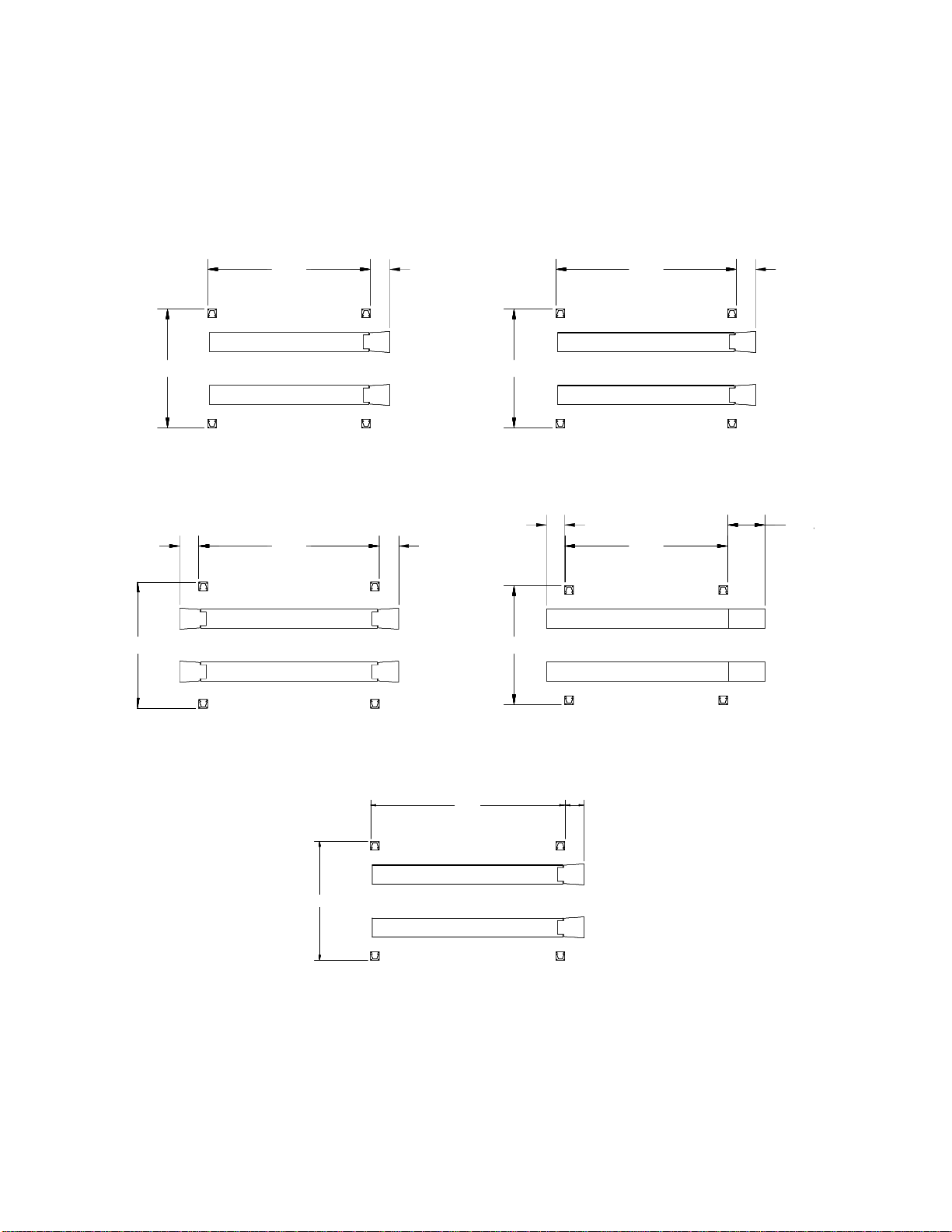
1. Determine the location for the lift installation. Fig. 1 gives the overall dimensions
of the lift, including the drive on ramps. The area must be level and there must
be free access to load and unload the vehicles.
There must be enough overhead clearance to raise vehicles six feet above the
floor. Thirteen feet is the recommended ceiling height.
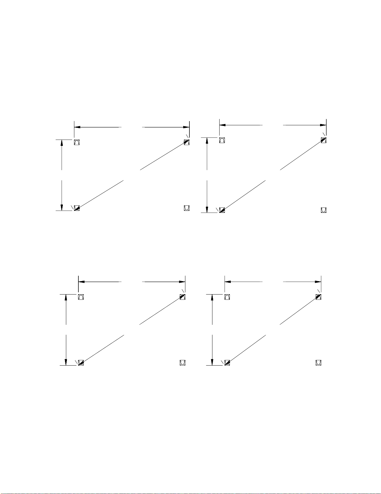
The floor must be 3000 psi concrete with a minimum thickness of four inches and
steel reinforced per local commercial practice. If pads are used, they must be
two feet square with a minimum thickness of twelve inches and steel reinforced
per local commercial practice. Fig. 2 gives the pad layout dimensions.
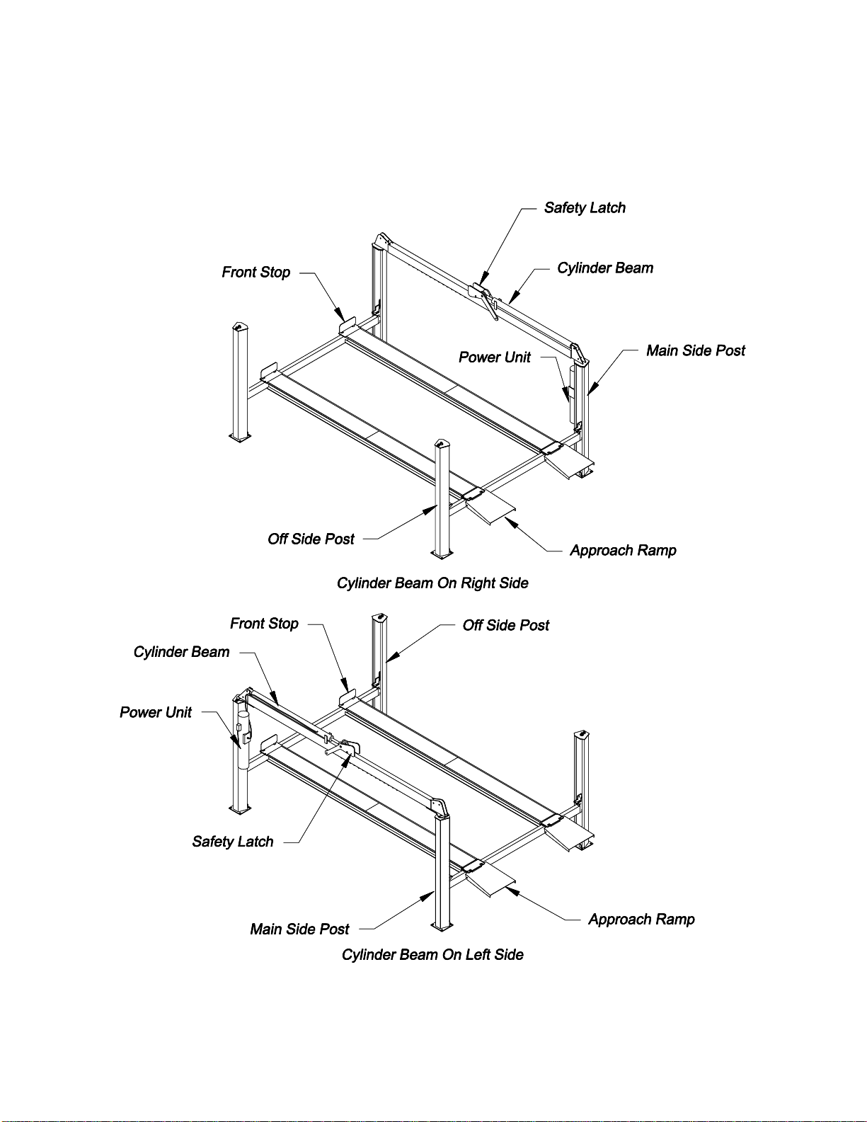
2. Refer to Fig. 3, General Arrangement. For muffler work, it is satisfactory to erect
the lift with the cylinder beam on the left, or drivers side. For alignment and work,
which require access to the front seat of the car, the top rail can be positioned on
the right side so it is out of the way.
3. Refer to Fig. 2 to get the dimensions for the post base locations. Refer to Fig. 1
to determine where to locate the sides and ends of the post base plate with
respect to walls and other obstacles at the installation. Include additional
clearance where required near walls and obstacles.
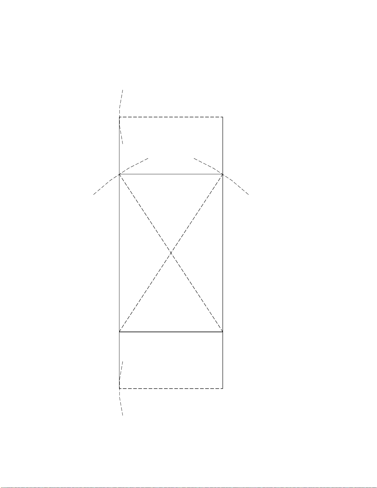
4. Once the location is determined, use a chalk line to mark base line A-B to locate
one side of the lift, refer to Fig 4. Use the width dimension from Fig 2 to measure
off the dimensions A-D and B-C. Draw arcs as illustrated in Fig. 4. Draw a chalk
line D-C tangent to the two arcs to establish the other side of the lift.
5. Mark on one of the two parallel lines the points 1 and 2 to establish the ends of
the post base plate as determined from Figs. 1 and 2. From points, 1 and 2
measure diagonally to the opposite parallel line to determine points 3 and 4.
Draw a chalk line between points 1 and 4 and points 2 and 3. The four lines
locate the four outside corners of the post base plates.
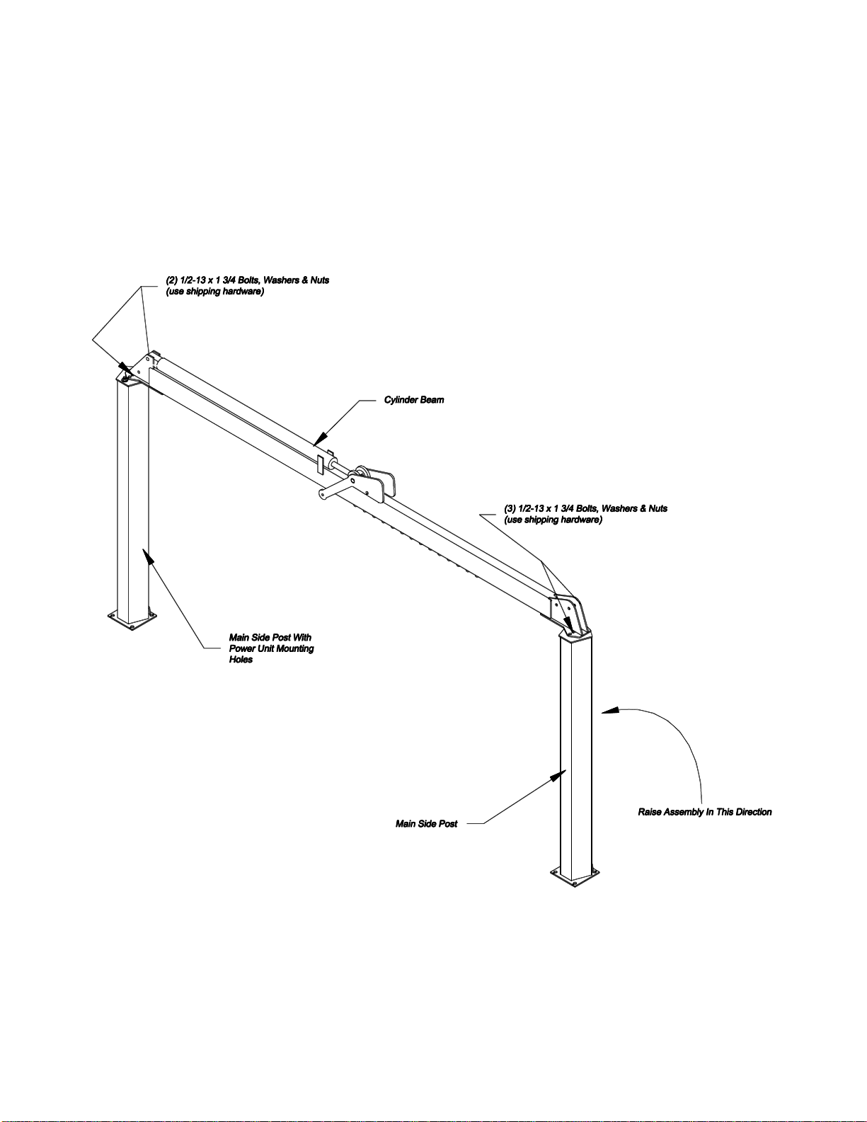
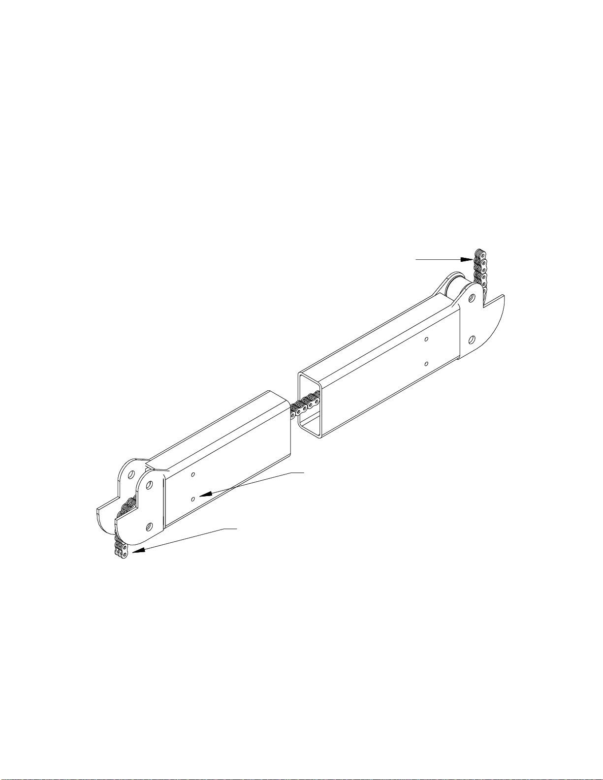
6. Position the cylinder beam and the two main side posts as shown in Fig. 5. The
main side post which has the drilled hole pattern on one side is the power unit
post. Bolt the cylinder beam to the main side posts using ½-13 x 1 3/4 bolts,
washers, and nuts (use shipping bolts). Use 2 bolts on the power post and 3 on
the other main side post.
7. Lift the assembled cylinder beam to the upright position. Place the post base
plate into their corners of the chalk line rectangle. Check the centering of the
bolting slots of the top rail and main side leg tops. Correct as necessary, the
main side post must be plumbed before tightening.
8. Review the concrete anchor bolt instructions near the back of this manual. Drill,
install, but do not tighten the 4 anchor bolts for the rear leg. DO ONLY THE
REAR MAIN SIDE POST AT THIS TIME.