NHP TemBreak PRO P User manual
Version
1.3.0
NHP Electrical Engineering Products
AU 1300 NHP NHP
NZ 0800 NHP NHP
nhp.com.au
nhp-nz.com
P Model Moulded Case CircuitBreaker
Basic Electronic Trip Unit from 160A up to630A
USER MANUAL
2
TemBreak PRO P_BE-UM-001-EN V1.3.0
Using this manual
Safety Precautions
Authorised Personnel Only
The product or system described in this documentation must be installed, operated and maintained by qualified personnel only. NHP or Terasaki accept no
responsibility for the consequences of the use of this equipment by unqualified personnel.
A qualified person is one with the necessary skills and knowledge of the construction and operation of the installation of electrical equipment and has been
trained to identify and avoid risks.
Appropriate use of NHP / Terasaki products
NHP / Terasaki products are intended to be used only for the applications described in the catalogue and technical documentation, which is dedicated to
them. If products and components from other manufacturers are used, they must be recommended or approved by NHP or Terasaki.
Appropriate use of NHP / Terasaki products during transport, storage, installation, assembly, commissioning, operation and maintenance is necessary to
ensure safe operation and without any problems.
The permissible ambient conditions must be met. The information contained in the technical documentation must be observed.
Publication of responsibility
The contents of this document have been reviewed to ensure that the reliability of the information is correct at time of publication.
NHP or Terasaki are not responsible for printing or damage resulting from errors. NHP or Terasaki reserve the right to make corrections and changes
needed in subsequent edition.
Warnings and notes
This documentation contains safety instructions that you must follow for your personal safety and to prevent damage to property.
Safety instructions, referring to your personal safety are reported in the literature by a safety alert symbol.
Safety warning symbols and the words below are classified according to the degree of risk.
WARNING: Indicates an imminently hazardous situation which, if it cannot be avoided, will result in death or
serious injury.
WARNING: Indicates a potentially hazardous situation which, if it cannot be avoided, can result serious injury or
death.
WARNING: Indicates a potentially hazardous situation which, if it cannot be avoided, may cause minor or
moderate injury.
Notice: Indicates a warning of property damage and can also indicate important operating and especially useful
information on the product, that it should pay particular attention to efficient and safe operation.

3
TemBreak PRO P_BE-UM-001-EN V1.3.0
Summary of Changes
This section highlights the details of changes made since the previous issue of this document.
The versioning convention used to track changes in this document follows the structure Vx.y.z where:
x: Major revision, where extensive changes are made which is generally incompatible with the previous version. Such changes may include new
products and/or features, or removal of information which is no longer relevant or applicable to the previous version
y: Minor revision, where changes made do not change the overall scope of the previous version, but may include additional information which
complements or corrects the previous version, or provides additional clarity on an existing topic.
z: Patch version, where small changes are made to correct minor errors or adjust existing text, charts, figures and/or images, and which do not
add or remove information from the previous version. Example changes may include spelling corrections, image re-sizing and adjustments,
updated images, etc.
Version
Publication date
Changes
By
V 1.0.0
19-Apr-2021
Initial release
D.NAT
V 1.1.0
26-Apr-2021
Product information corrections
D.NAT
V 1.2.0
29-Apr-2021
Neutral Protection information correction
D.NAT
V 1.3.0
13-May-2021
Clearance distance corrections
N.ALEX

4
TemBreak PRO P_BE-UM-001-EN V1.3.0
Table of Contents
Using this manual 2
Safety Precautions 2
Summary of Changes 3
Table of Contents 4
Introduction 5
Who Should Use This Manual? 5
Additional resources 5
Terminology and Abbreviations 6
Product Information 7
Part Number Break Down 8
Available MCCBs in the TemBreak PRO range: 9
P160_BE and P250_BE Information 10
P400_BE Information 11
P630_BE Information 12
Internal Accessories 13
Auxiliary & Alarm Switches 13
Auxiliary Contact 13
Alarm Contact 13
Shunt Trip 14
Under Voltage Trips 14
Plugs & Ports 15
Installation 16
Precautions 16
Mounting Angles 16
Direction of Power Supply 16
Clearances 17
Internal Accessory Mounting Locations 19
P160 internal accessories combination 19
P250 internal accessories combination 20
P400/630 internal accessories combination 21
Alarm, Shunt & UVT Installation 22
Standard Alarm & Auxiliary installation 22
Shunt & UVT installation 23
Protection Settings 24
Trip Curve 24
Long Time Delay (LTD) protection 25
Adjusting Ir(Current) 26
Adjusting tr(Time Delay) 27
Thermal memory / Hot–Cold start mode 28
Short Time Delay Protection (STD) 29
Adjusting Isd (Current) 30
Adjusting tsd (Time Delay) 31
Isd Time Delay Adjustment Settings (ms) 31
I2t function for STD 32
Thermal Self Protection 34
Instantaneous Protection (INST) 35
Adjusting Ii(Current) 35
Ground/Earth Fault Protection (GF) 36
Neutral Protection (NP) 37
Alarms & Indication 38
System Alarms 38
Trip Alarm 39
PTA (Pre-Trip Alarm) 40
OAC and PTA cable 40
OCR Power Supply 41
Commissioning 42
LTD Adjustments (Ir, tr) 42
STD Adjustments (Isd, tsd) 43
INST Protection Adjustments (Ii) 44
INST Protection Only Setting 45
LSIG 3P –GF Protection Adjustments (Ig) 46
LSIG 4P –NP and GF Protection Adjustments (IN, Ig) 47
Troubleshooting 48
Annex A –Dimensions 50
P160 Dimensions 50
P250 Dimensions 51
P400 Dimensions 52
P630 Dimensions 53
Annex B –Trip Curves 54
Annex C –I2t Let-Through Curves 55
P160_BE 55
P250_BE 56
P400_BE 57
P630_BE 58
Annex D –Peak Let Through Curves 59
P160_BE 59
P250_BE 60
P400_BE 61
P630_BE 62
Annex E –Watts Loss 63
Annex F –Rated Temperature Tables 64

5
TemBreak PRO P_BE-UM-001-EN V1.3.0
Introduction
This user manual describes the TemBreak PRO Basic Electronic (P_BE) MCCB features and instructions for use, and provides information for
commissioning and configuring.
Some additional features may require the use of additional products and accessories to achieve full utilization of that feature. Refer the respective User
Manual in the TemBreak PRO series for additional information on the respective product.
Who Should Use This Manual?
This manual aims to provide users, electricians, panel builders and maintenance personnel, with the technical information required for commissioning and
operation of the NHP / Terasaki TemBreak PROP_BE MCCB.
Users of this document must have at minimum a basic understanding of electrical circuit protection topics including (but not limited to):
-
Power distribution and reticulation
-
Circuit protection devices
-
Fault currents
-
Arc faults
-
Temperature rise and thermal derating of switchgear
Additional resources
The following resources contain additional information which should be read in conjunction with this document.
Resource
Description
NHP/Terasaki TemBreak PRO P_BE Installation
Instructions
P160_3_BE-IN-001-EN
P160_4_BE-IN-001-EN
P250_3_BE-IN-001-EN
P250_4_BE-IN-001-EN
P400_3_BE-IN-001-EN
P400_4_BE-IN-001-EN
P630_3_BE-IN-001-EN
P630_4_BE-IN-001-EN
Information on installing, mounting, and wiring the TemBreak PRO Basic Electronic
MCCB.
Notice: Not all OCRs in the TemBreak PRO series are identical. This document specifically covers the P_BE
OCRs only. Refer to the respective OCR User Manual (e.g. B_SE, P_SE, etc.) for information and instructions
on other OCRs in the TemBreak PRO series.

Introduction
6
TemBreak PRO P_BE-UM-001-EN V1.3.0
Terminology and Abbreviations
Abbreviation
Description
Abbreviation
Description
ACP
Auxiliary Communications port: Plug for Smart auxiliary /
alarm contact block
MIP
Maintenance Interface Port: Plug for temporary
connection to OCR testing, servicing, and maintenance
tools
AL
Alarm: An auxiliary contact indicating trip status
N
Neutral
ASCII
American Standard Code for Information Interchange
NP
Neutral Protection
AX or AUX
Auxiliary: Auxiliary contact indicating open / closed
OAC
Optional Alarm Contact: Connection connector optional
alarm output contact
BE
Basic Electronic Trip Unit (dial type, LSI and LSIG)
OCR
Over Current Relay
CCW
Connected Components Workbench software
P or PTA
Pre-trip Alarm
CIP 1 2
1Communication Interface Port: Plug for control power
and data for use with the TPED remote display and
TPCM communication module
2Common Industrial Protocol
PDU
Protocol Data Unit
CRC
Cyclic Redundancy Check –error-detecting code used at
the end of each Modbus message
PELV
Protected Extra Low Voltage (earthed system)
dec
Decimal (base-10) numbering system
PTA
Pre-Trip Alarm: is a programmable output contact to
advise when a trip may be imminent.
DINT
Signed Double Integer datatype (4 bytes or 32 bits in
length)
RTU
Remote Terminal Unit
EIPM
TemBreak PRO Ethernet/IP Module
S or STD
Short Time Delay Protection
FF
Fixed Thermal and Fixed Magnetic
SE
Smart Energy Trip Unit
FM
Fixed Thermal and Adjustable Magnetic
SELV
Separated Extra Low Voltage
G or GF
Ground Fault Protection
SN
Solid Neutral
hex
Hexadecimal (base-16) numbering system
SSID
Service Set Identifier (name of the Wi-Fi wireless
network)
I or INST
Instantaneous Protection
STR
String datatype
IEC
International Electrotechnical Commission
TCP
Transmission Control Protocol
IEEE
Institute of Electrical and Electronics Engineers
TF
Adjustable Thermal and Fixed Magnetic
Ig
Ground Fault Protection Current
THD
Total Harmonic Distortion
Ii
Instantaneous Protection Current
TM
Adjustable Thermal Magnetic
In
Rated Current
TPCM
TemCom PRO Communication Module
IN
Neutral Protection Current
TPED
TemView PRO External Display
INT
Signed Integer datatype (2 bytes or 16 bits in length)
tr
LTD Time delay
IP
International Protection (Ingress Protection)
tsd
STD Time delay
Ir
LTD Protection Current
ttsp
Thermal Self-Protection Time delay
Isd
STD Protection Current
UDINT
Unsigned Integer (2 bytes or 16-bits in length)
Itsp
Thermal Self-Protection Current
UINT
Unsigned Integer (2 bytes or 16 bits in length)
L or LTD
Long Time Delay Protection
ULINT
Unsigned Long Integer datatype (8 bytes or 64 bits in
length)
LCD
Liquid Crystal Display (LCD)
URLs
Uniform Resource Locator (address of an Internet
website)
LED
Light Emitting Diode
WORD
2 bytes or 16-bits of data
LINT
Signed Long Integer datatype (8 bytes or 64 bits in
length)
ZSI
Zone Selective Interlocking (zone selectivity)
LSI
Long Time, Short Time and Instantaneous Protection
θ
Thermal imaging value
LSIG
Long Time, Short Time, Instantaneous and Ground Fault
Protection
θC
Cold start mode thermal imaging value
MCCB
Moulded Case Circuit Breaker
θH
Hot start mode thermal imaging value
microSD
Micro Secure Digital
θtrip
Thermal imaging value tripping threshold

7
TemBreak PRO P_BE-UM-001-EN V1.3.0
Product Information
The TemBreak PRO P model Basic Electronic MCCB with trip unit type P_BE, in addition to protecting against overloads and short circuits, offers flexibility
via provide fully adjustable LSI(G) (long time, short time, instantaneous, ground fault) protection settings via preset rotary switches as well as a host of other
standard or optional features. This allows for improved selectivity combinations between MCCBs or other circuit breaker types.
Features
-LSI or LSIG
-Setting by rotary dial
-Over temperature alarm LED
-Signalling the OCR LED status (Ready)
-Signalling PTA overload pre-warning LED
-LED signalling overload alarm (>Ir)
-Possible adjustment of thresholds and time delays for LSIG 6)
-Possible adjustment of the protection of neutral pole on 4-pole versions (neutral pole positioned to the right)
Frame Sizes
-P160
-P250
-P400
-P630
Protection Functions
-Long Time Delay
-Short Time Delay
-Instantaneous
-Ground Fault (LSIG model)
-Neutral Protection (LSIG 4P model)
Additional Certificates

Product Information
8
TemBreak PRO P_BE-UM-001-EN V1.3.0
Part Number Break Down
P
160
F
2
4
160
BE
G
a)
b)
c)
d)
e)
f)
g)
h)
a) Model Type
A
Basic applications
(160…250 A)
P
Mid to advanced applications
(160…630 A)
B
High current, high kA applications
(160…1600 A)
ZS
Earth Leakage applications
(125…800 A)
XS
Highest current applications
(2000…3200 A)
b) Ampere Frame
125
A
160
A
250
A
400
A
630
A
800
A
1000
A
1250
A
1600
A
2000
A
2500
A
3200
A
c) Short Circuit Break Capacity Icu (kA)
R
200 kA
L
150 kA
P
125 kA
S
110 kA
G
100 kA
HL
85 kA
H
70 kA
M
65 kA
N
50 kA
F
36 kA
E
25 kA
D
Switch
d) Pole Pitch Size (mm) 1)
1
25
2
30
3
35
e) No. of Poles
1
6)
2
7)
3
4
f) Trip Unit Rating (In)
In
x A
g) Trip Unit Type
TF
Adj Thermal Fix Magnetic 3)
FF
Fix Thermal Fix Magnetic 3)
FM
Fix Thermal Adj Magnetic 8)
TM
Adj Thermal Adj Magnetic
SX
Smart Ammeter 4) 5)
BE
Basic Electronic 5)
SE
Smart Energy 5)
NN
Non-Auto Switch
h) Trip Unit Option
G
Ground Fault 2)
N
Neutral 2)
P
Pre-Trip Alarm 2)
SN
Solid Neutral 8)
1. 160AF only
2. For P_SE versions these features are standard and therefore are not added to the end of the part number.
3. Only available in A & ZS models
4. Only available in B models
5. Not available in A models
6. Only available in A and B models (FF Only Trip Unit)
7. Not available in A and B models (FF Only Trip Unit)
8. ZS Models
Notice: Not all combinations are possible. Confirm part number combination with NHP for availability.

Product Information
9
TemBreak PRO P_BE-UM-001-EN V1.3.0
Available MCCBs in the TemBreak PRO range:
Rating
Short Circuit Break Capacity
(kA)
Frame Size
160
250
400
630
800
1000
1250
1600
2000
2500
3200
E
25
A160E –TF
A160E –FF
B160E –FF
A250E –TM
P400E-TM
P630E –TM
F
36
A160F –TF
P160F –FF
P160F –TM
P160F –BE
P160F –BEG
P160F –SE
A250F –TM
P250F –TM
P250F –BE
P250F –BEG
P250F –SE
P400F –TM
P400F –BE
P400F –BEG
P400F –SE
P630F –TM
P630F –BE
P630F –BEG
P630F –SE
B800F –TM
N
50
P160N –TM
P160N –BE
P160N –BEG
P160N –SE
P250N –TM
P250N –BE
P250N –BEG
P250N –SE
P400N –TM
P400N –BE
P400N –BEG
P400N –SE
P630N –TM
P630N –BE
P630N –BEG
P630N –SE
B800N –TM
B800N –BE
B800N –SX
B800N –SE
B1000N –BE
B1000N –SX
B1000N –SE
B1250N –BE
B1600N –BE
H
70
P160H –TM
P160H –BE
P160H –BEG
P160H –SE
P250H –TM
P250H –BE
P250H –BEG
P250H –SE
P400H –TM
P400H –BE
P400H –BEG
P400H –SE
P630H –TM
P630H –BE
P630H –BEG
P630H –SE
B800H –TM
B800H –BE
B800H –SX
B800H –SE
B1000H –BE
B1000H –SX
B1000H –SE
B1250H –BE
HL
85
B1250HL –BE
B1600HL –BE
XS2000HL –BE
XS2500HL –BE
XS3200HL –BE
G
100
B800G –TM
B800G –BE
B800G –SX
B800G –SE
S
110
P400S –TM
P400S –BE
P400S –BEG
P400S –SE
P630S –TM
P630S –BE
P630S –BEG
P630S –SE
P
125
B160P –TM
B250P –TM
B250P –BE
B250P –SE
B400P –BE
B800P –BE
B800P –SX
B800P –SE
R
200
B160R –TM
B250R –TM
B400R –BE
B800R –BE
B800R –SX
B800R –SE
D
Switch
A160D –NN
P160D –NN
A250D –NN
P250D –NN
P400D –NN
P630D –NN
B800D –NN
B1000D –NN
B1250D –NN
B1600D –NN
XS2000D –NN
XS2500D –NN
XS3200D –NN
Product Information
10
TemBreak PRO P_BE-UM-001-EN V1.3.0
P160_BE and P250_BE Information
Frame / Model
Attribute
Unit
Condition
P160F
P160N
P160H
P250F
P250N
P250H
Number of Poles
3, 4
3, 4
3, 4
3, 4
3, 4
3, 4
Nominal current ratings
ICT
(A)
50°C
40 A
40 A
40 A
40 A
40 A
40 A
Trip unit ratings
100 A
100 A
100 A
100 A
100 A
100 A
160 A
160 A
160 A
160 A
160 A
160 A
─
─
─
250 A
250 A
250 A
Electrical characteristics
Rated maximum operational voltage
Ue
(V)
AC 50/60 Hz
690
690
690
690
690
690
(V)
DC
─
─
─
─
─
─
Rated insulation voltage
Ui
(V)
800
800
800
800
800
800
Rated impulse withstand voltage
Uimp
(kV)
8
8
8
8
8
8
Selectivity category
A
A
A
A
A
A
Rated short time withstand current
Icw
(kA)
0.4 sec
─
─
─
─
─
─
Ultimate breaking capacity
Icu
(kA)
690 Vac
6
6
6
6
6
6
(IEC, JIS, AS/NZS)
400 /415 Vac
36
50
70
36
50
70
240 Vac
50
85
85
50
85
85
Service breaking capacity
Ics
(kA)
690 Vac
6
6
6
6
6
6
(IEC, JIS, AS/NZS)
400 /415 Vac
36
50
50
36
50
50
220 /240 Vac
50
85
85
50
85
85
Protection - Over Current Release types
Std Standard
Opt Optional
─Not Available
M Req Module Required
BE 6 dial Adjustable LSI
Std
Std
Std
Std
Std
Std
BE-G 7 dial Adjustable LSIG (Ground Fault)
Std
Std
Std
Std
Std
Std
BE Instantaneous only setting (ICB) 1)
Std
Std
Std
Std
Std
Std
LT Adjustable 40% to 100% in 1% increments
Std
Std
Std
Std
Std
Std
Instantaneous setting independently adjustable
Std
Std
Std
Std
Std
Std
Installation (Std / Opt / ─ )
Std Standard
Opt Optional
─Not Available
Front connection (FC)
Std
Std
Std
Std
Std
Std
Extension bar (FB)
Opt
Opt
Opt
Opt
Opt
Opt
Cable tunnel clamp (FW)
Opt
Opt
Opt
Opt
Opt
Opt
Rear Connection (RC)
Opt
Opt
Opt
Opt
Opt
Opt
DIN rail adaptor
Opt
Opt
Opt
Opt
Opt
Opt
Withdrawable mechanism
Opt
Opt
Opt
Opt
Opt
Opt
Plug-in
Opt
Opt
Opt
Opt
Opt
Opt
Reverse supply connection possible to 440V
Yes
Yes
Yes
Yes
Yes
Yes
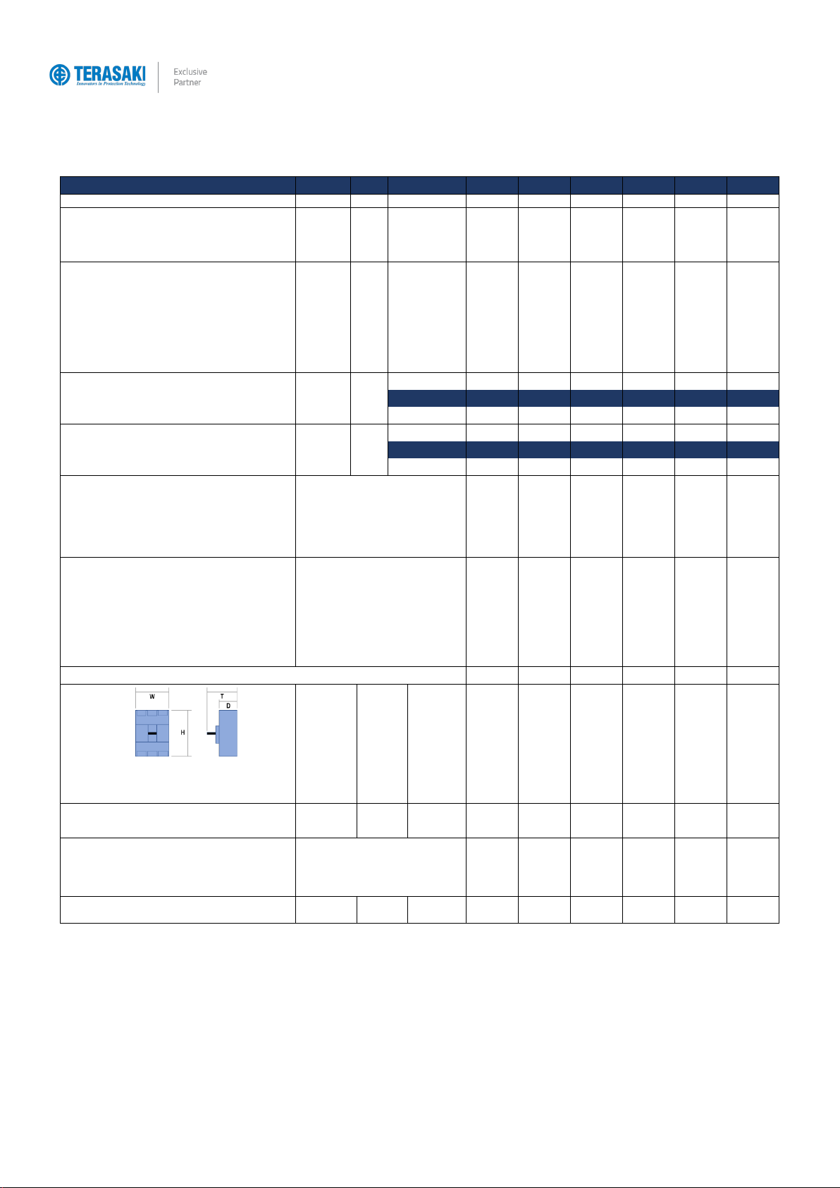
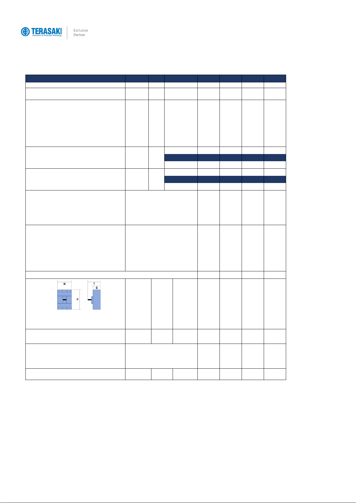
Dimensions
H
(mm)
165
165
165
165
165
165
W
(mm)
1 pole
─
─
─
─
─
─
2 pole
─
─
─
─
─
─
3 pole
90
90
90
105
105
105
4 pole
120
120
120
140
140
140
D
(mm)
68
68
68
68
68
68
T
(mm)
95.5
95.5
95.5
95.5
95.5
95.5
Weight
W
(kg)
3 pole
1.0
1.0
1.0
1.5
1.5
1.5
4 pole
1.3
1.3
1.3
2
2
2
Operation options (Std / Opt / ─ )
Std Standard
Opt Optional
─Not Available
Toggle operation
Std
Std
Std
Std
Std
Std
Extension handle TP-HS/HP or Direct mount T2HB
Opt
Opt
Opt
Opt
Opt
Opt
Motor operation TP-MC
Opt
Opt
Opt
Opt
Opt
Opt
Endurance
Electrical
Cycles
415 Vac
30000
30000
30000
10000
10000
10000
Mechanical
Cycles
50000
50000
50000
30000
30000
30000
Product Information
11
TemBreak PRO P_BE-UM-001-EN V1.3.0
P400_BE Information
Frame / Model
Attribute
Unit
Condition
P400F
P400N
P400H
P400S
Number of Poles
3, 4
3, 4
3, 4
3, 4
Nominal current ratings
ICT
(A)
50°C
Calibration
250 A
250 A
250 A
250 A
Trip unit ratings
400 A
400 A
400 A
400 A
Electrical characteristics
Rated maximum operational voltage
Ue
(V)
AC 50/60 Hz
690
690
690
690
(V)
DC
─
─
─
─
Rated insulation voltage
Ui
(V)
800
800
800
800
Rated impulse withstand voltage
Uimp
(kV)
8
8
8
8
Selectivity category
B
B
B
B
Rated short time withstand current
Icw
(kA)
0.4 sec
5
5
5
5
Ultimate breaking capacity
Icu
(kA)
690 Vac
7
12
12
12
(IEC, JIS, AS/NZS)
400 /415 Vac
36
50
70
110
240 Vac
50
85
100
125
Service breaking capacity
Ics
(kA)
690 Vac
7
12
12
12
(IEC, JIS, AS/NZS)
400 /415 Vac
36
50
70
110
220 /240 Vac
50
85
100
125
Protection - Over Current Release types
Std Standard
Opt Optional
─Not Available
M Req Module Required
BE 6 dial Adjustable LSI
Std
Std
Std
Std
BE-G 7 dial Adjustable LSIG (Ground Fault)
Std
Std
Std
Std
BE Instantaneous only setting (ICB) 1)
Std
Std
Std
Std
LT Adjustable 40% to 100% in 1% increments
Std
Std
Std
Std
Instantaneous setting independently adjustable
Std
Std
Std
Std
Installation (Std / Opt / ─ )
Std Standard
Opt Optional
─Not Available
Front connection (FC)
Std
Std
Std
Std
Extension bar (FB)
Std
Std
Std
Std
Cable tunnel clamp (FW)
Opt
Opt
Opt
Opt
Rear connection (RC)
Opt
Opt
Opt
Opt
DIN rail adaptor
─
─
─
─
Withdrawable mechanism
Opt
Opt
Opt
Opt
Plug-in
Opt
Opt
Opt
Opt
Reverse supply connection possible to 440V
Yes
Yes
Yes
Yes
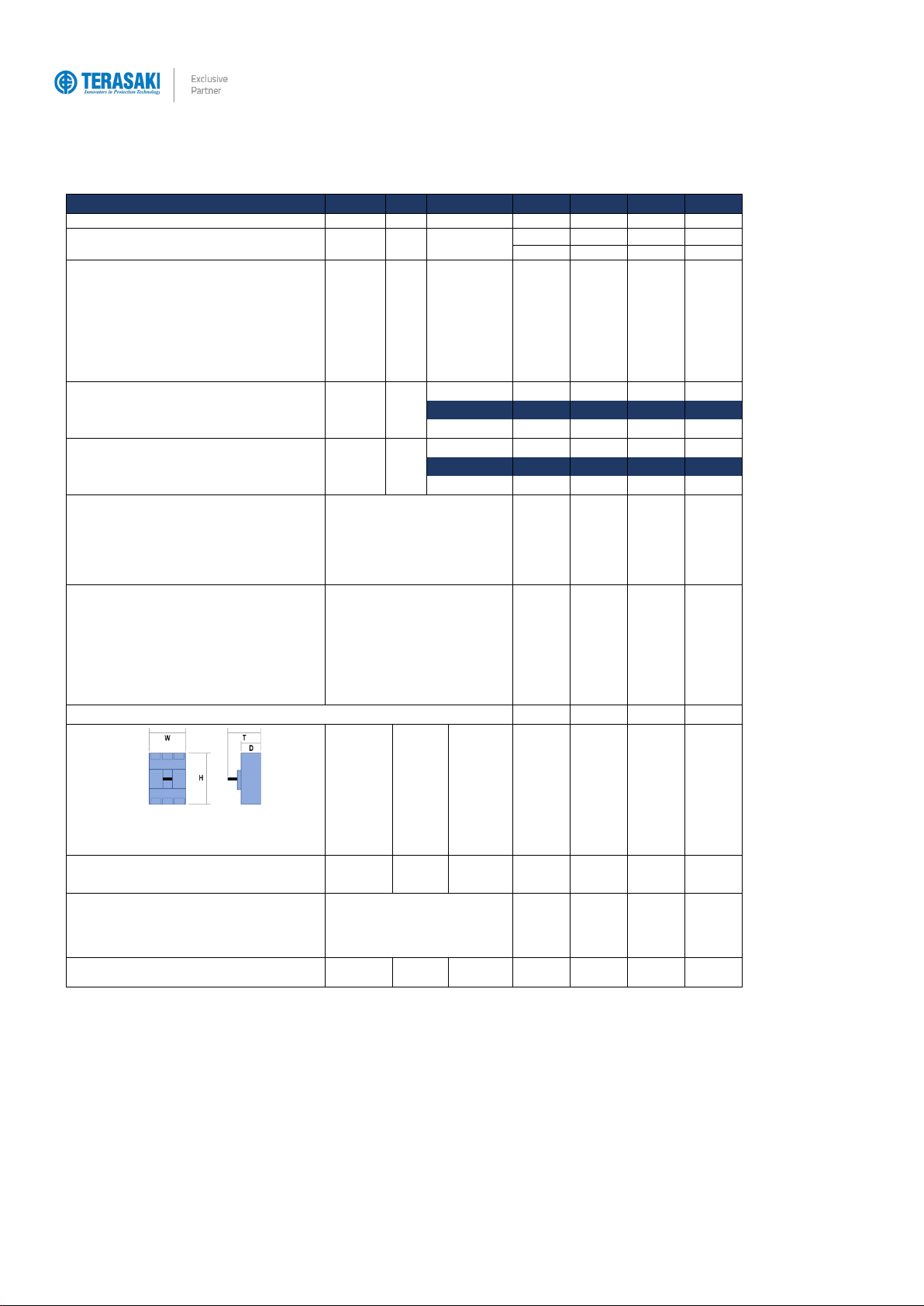
Dimensions
H
(mm)
260
260
260
260
W
(mm)
1 pole
─
─
─
─
2 pole
─
─
─
─
3 pole
140
140
140
140
4 pole
185
185
185
185
D
(mm)
103
103
103
103
T
(mm)
145
145
145
145
Weight
W
(kg)
3 pole
4.3
4.3
4.3
4.3
4 pole
5.7
5.7
5.7
5.7
Operation options (Std / Opt / ─ )
Std Standard
Opt Optional
─Not Available
Toggle operation
Std
Std
Std
Std
Extension handle TP-HS/HP or Direct mount T2HB
Opt
Opt
Opt
Opt
Motor operation TP-MC
Opt
Opt
Opt
Opt
Endurance
Electrical
Cycles
415 Vac
6000
6000
6000
6000
Mechanical
Cycles
15000
15000
15000
15000
Product Information
12
TemBreak PRO P_BE-UM-001-EN V1.3.0
P630_BE Information
Frame / Model
Attribute
Unit
Condition
P630F
P630N
P630H
P630S
Number of Poles
3, 4
3, 4
3, 4
3, 4
Nominal current ratings
ICT
(A)
50°C
630A
630A
630A
630A
Trip unit ratings
Calibration
Electrical characteristics
Rated maximum operational voltage
Ue
(V)
AC 50/60 Hz
690
690
690
690
(V)
DC
─
─
─
─
Rated insulation voltage
Ui
(V)
800
800
800
800
Rated impulse withstand voltage
Uimp
(kV)
8
8
8
8
Selectivity category
A
A
A
A
Rated short time withstand current
Icw
(kA)
0.4 sec
─
─
─
─
Ultimate breaking capacity
Icu
(kA)
690 Vac
7
12
12
12
(IEC, JIS, AS/NZS)
400 /415 Vac
36
50
70
110
240 Vac
50
85
100
125
Service breaking capacity
Ics
(kA)
690 Vac
7
12
12
12
(IEC, JIS, AS/NZS)
400 /415 Vac
36
50
70
110
220 /240 Vac
50
85
100
125
Protection - Over Current Release types
Std Standard
Opt Optional
─Not Available
M Req Module Required
BE 6 dial Adjustable LSI
Std
Std
Std
Std
BE-G 7 dial Adjustable LSIG (Ground Fault)
Std
Std
Std
Std
BE Instantaneous only setting (ICB) 1)
Std
Std
Std
Std
LT Adjustable 40% to 100% in 1% increments
Std
Std
Std
Std
Instantaneous setting independently adjustable
Std
Std
Std
Std
Installation (Std / Opt / ─ )
Std Standard
Opt Optional
─Not Available
Front connection (FC)
Std
Std
Std
Std
Extension bar (FB)
Std
Std
Std
Std
Cable tunnel clamp (FW)
Opt
Opt
Opt
Opt
Rear connection (RC)
Opt
Opt
Opt
Opt
DIN rail adaptor
─
─
─
─
Withdrawable mechanism
Opt
Opt
Opt
Opt
Plug-in
Opt
Opt
Opt
Opt
Reverse supply connection possible to 440V
Yes
Yes
Yes
Yes
Dimensions
H
(mm)
260
260
260
260
W
(mm)
1 pole
─
─
─
─
2 pole
─
─
─
─
3 pole
140
140
140
140
4 pole
185
185
185
185
D
(mm)
103
103
103
103
T
(mm)
145
145
145
145
Weight
W
(kg)
3 pole
5.0
5.0
5.0
5.0
4 pole
6.6
6.6
6.6
6.6
Operation options (Std / Opt / ─ )
Std Standard
Opt Optional
─Not Available
Toggle operation
Std
Std
Std
Std
Extension handle TP-HS/HP or Direct mount T2HB
Opt
Opt
Opt
Opt
Motor operation TP-MC
Opt
Opt
Opt
Opt
Endurance
Electrical
Cycles
415 Vac
4000
4000
4000
4000
Mechanical
Cycles
15000
15000
15000
15000

13
TemBreak PRO P_BE-UM-001-EN V1.3.0
Internal Accessories
Internal accessories include Auxiliary and Alarm contacts, Shunt Trip and Undervoltage Trip (UVT) modules, which may be installed under the front cover of
the MCCB in various combinations to provide additional functionality and connection with external control circuits.
Auxiliary & Alarm Switches
Auxiliary Contact
An auxiliary contact can be installed to indicate whether an MCCB is Open (both OFF and Tripped positions) or
Closed (ON). Auxiliary contacts come in either general purpose or micro-switch type, with some combinations pre-
wired or with terminals. Each contact type is provided as a single change-over switching arrangement (1x C/O).
Alarm Contact
An alarm contact can be installed to indicate whether an MCCB is in the Tripped or Not Tripped position (ON, OFF).
Alarm contacts come in either general purpose or micro-switch type, with some combinations pre-wired or with
terminals. Each contact type is provided as a single change-over switching arrangement (1x C/O).
Part Number
Description
Contact Type
Connection Type
T2AX00LML3SWA
Auxiliary
General purpose
Pre-wired
T2AX00LML3STA
Auxiliary
General purpose
Terminal
T2AX00LML3RWA
Auxiliary
Micro-switch
Pre-wired
T2AL00LML3SWA
Alarm; left side only
General purpose
Pre-wired
T2AL00LML3STA
Alarm; left side only
General purpose
Terminal
T2AL00LML3RWA
Alarm; left side only
Micro-switch
Pre-wired
General purpose contact
Micro-switch contact
AC (V)
DC (V)
Minimum Load
DC (V)
Minimum Load
Volts
(V)
Amperes (A)
Volts
(V)
Amperes (A)
Volts
(V)
Amperes (A)
Resistive
Load
Inductive
Load
Resistive
Load
Inductive
Load
Resistive
Load
480
─
─
250
─
─
100 mA @ 15 Vdc
30
0.1
1 mA @ 5 Vdc
250
3
2
125
0.4
0.05
125
3
2
30
3
2
Internal Accessories
14
TemBreak PRO P_BE-UM-001-EN V1.3.0
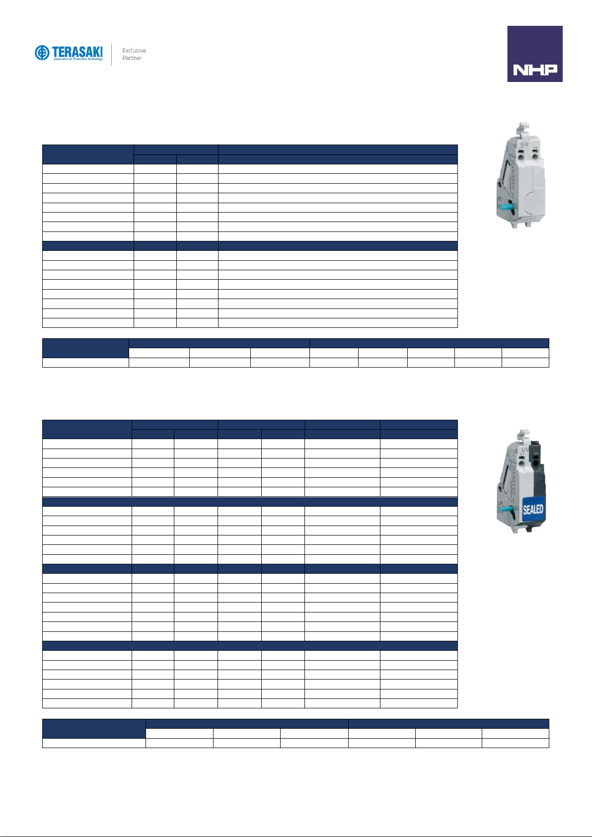
Shunt Trip
A shunt (normally de-energized) can be installed to trip the MCCB by applying voltage to the shunt coil.
Part Number
Rated voltage
Connection Type
AC (V)
DC (V)
T2SH00LA10T
110
─
Terminal
T2SH00LA20T
230…240
─
Terminal
T2SH00LA40T
400…415
─
Terminal
T2SH00LD01T
─
12
Terminal
T2SH00LD02T
─
24
Terminal
T2SH00LD04T
─
48
Terminal
T2SH00LD10T
─
110
Terminal
T2SH00LD20T
─
230
Terminal
T2SH00LA10WA
110
─
Pre-wired cage clamp
T2SH00LA20WA
230…240
─
Pre-wired cage clamp
T2SH00LA40WA
400…415
─
Pre-wired cage clamp
T2SH00LD01WA
─
12
Pre-wired cage clamp
T2SH00LD02WA
─
24
Pre-wired cage clamp
T2SH00LD04WA
─
48
Pre-wired cage clamp
T2SH00LD10WA
─
110
Pre-wired cage clamp
T2SH00LD20WA
─
230
Pre-wired cage clamp
Rated voltage
AC (V)
DC (V)
100…120
200…240
380...450
12
24
48
100…120
200…240
Excitation current (mA)
16.0
16.0
6.2
160.0
124.0
32.0
14.0
12.0
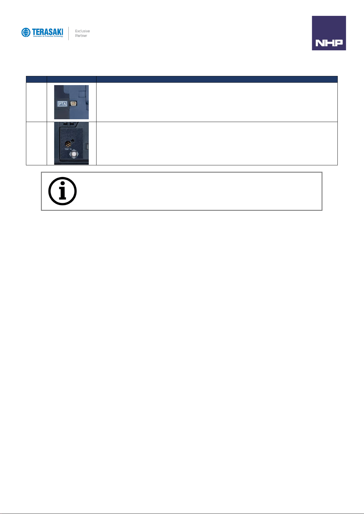
Under Voltage Trips
A UVT (normally energized) can be installed to trip the MCCB removing voltage from the UVT coil.
Part Number
Rated voltage
Compatible MCCB
Connection Type
Notes
AC (V)
DC (V)
3P
4P
T2UV00LA10NT
110
─
All
P160 / 250
Terminal
Instantaneous
T2UV00LA20NT
230…240
─
All
P160 / 250
Terminal
Instantaneous
T2UV00LA40NT
400…440
─
All
P160 / 250
Terminal
Instantaneous
T2UV00LD02NT
─
24
All
P160 / 250
Terminal
Instantaneous
T2UV00LD10NT
─
110
All
P160 / 250
Terminal
Instantaneous
T2UV00LD20NT
─
230
All
P160 / 250
Terminal
Instantaneous
T2UV00LA10DS
110
─
All
P160 / 250
Terminal
Time Delay 500ms
T2UV00LA24DS
230…240
─
All
P160 / 250
Terminal
Time Delay 500ms
T2UV00LA45DS
440…450
─
All
P160 / 250
Terminal
Time Delay 500ms
T2UV00LD02DS
─
24
All
P160 / 250
Terminal
Time Delay 500ms
T2UV00LD10DS
─
110
All
P160 / 250
Terminal
Time Delay 500ms
T2UV00LD24DS
─
230
All
P160 / 250
Terminal
Time Delay 500ms
T2UV00LA10DL
110
─
─
P400 / 630
Terminal
Time Delay 500ms
T2UV00LA24DL
230…240
─
─
P400 / 630
Terminal
Time Delay 500ms
T2UV00LA40DL
380…415
─
─
P400 / 630
Terminal
Time Delay 500ms
T2UV00LA45DL
440…450
─
─
P400 / 630
Terminal
Time Delay 500ms
T2UV00LD02DL
24
─
P400 / 630
Terminal
Time Delay 500ms
T2UV00LD10DL
110
─
P400 / 630
Terminal
Time Delay 500ms
T2UV00LD24DL
230
─
P400 / 630
Terminal
Time Delay 500ms
T2UV00LA10NWA
110
─
All
P160 / 250
Pre-wired cage clamp
Instantaneous
T2UV00LA20NWA
230…240
─
All
P160 / 250
Pre-wired cage clamp
Instantaneous
T2UV00LA40NWA
440…450
─
All
P160 / 250
Pre-wired cage clamp
Instantaneous
T2UV00LD02NWA
─
24
All
P160 / 250
Pre-wired cage clamp
Instantaneous
T2UV00LD10NWA
─
110
All
P160 / 250
Pre-wired cage clamp
Instantaneous
T2UV00LD20NWA
─
230
All
P160 / 250
Pre-wired cage clamp
Instantaneous
Rated Voltage
AC (V)
DC (V)
100…120
200…240
380…450
24
100…120
200…240
Excitation current (mA)
1.3
1.1
2.0
22.0
9.0
3.7
15
TemBreak PRO P_BE-UM-001-EN V1.3.0
Plugs & Ports
The P_BE circuit breaker is equipped with specific connectors for connecting interfacing devices and accessories.
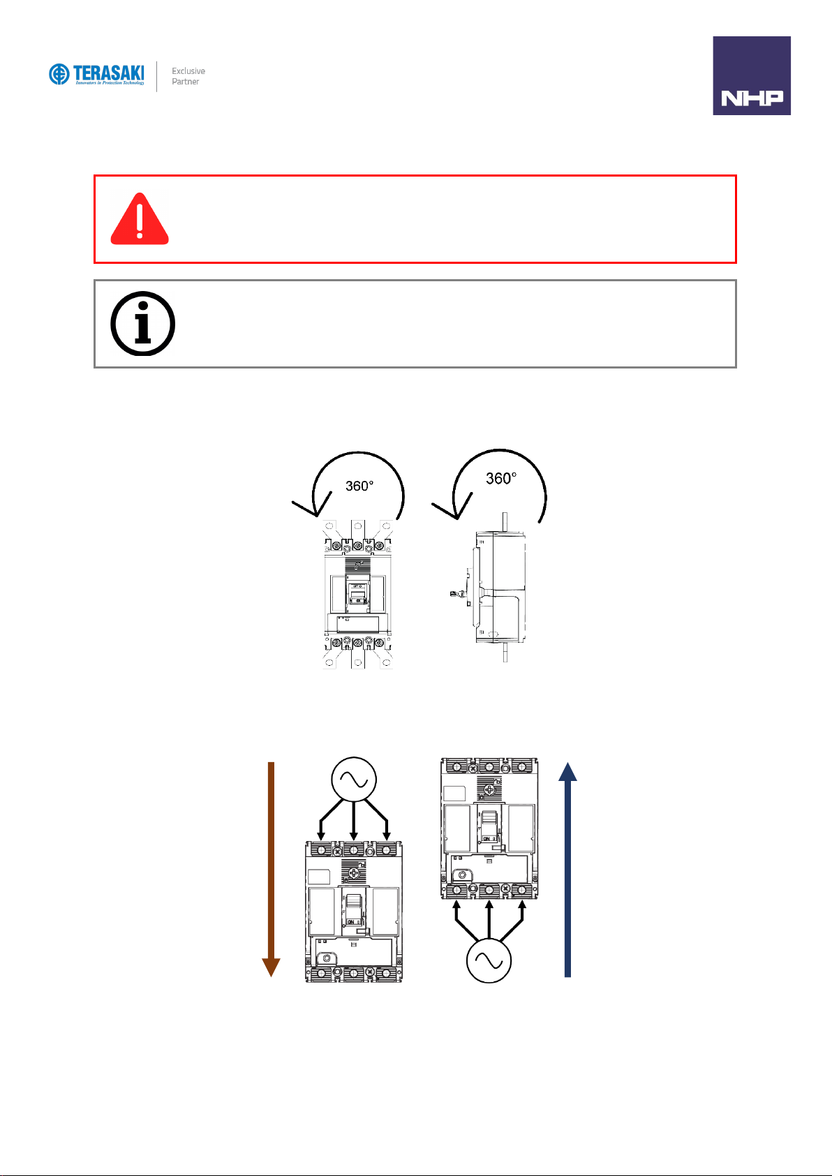
Port
Description
PTA
Used to connect the PTA output contact to send the pre-trip alarm over a local signalling circuit.
Located on the outside left-hand side of the MCCB.
MIP
Maintenance Interface Port –for temporary connection to OCR testing, servicing, and maintenance tools.
Located to the right of the embedded display front cover.
Notice: Port images are representative only. Locations differ slightly for the various ampere frame sizes
16
TemBreak PRO P_BE-UM-001-EN V1.3.0
Installation
Precautions
Mounting Angles
TemBreak PRO MCCBs may be mounted at any angle without affecting performance.
Direction of Power Supply
Power supply may be fed in either direction with respect to the MCCB without affecting performance.
WARNING: To prevent electrical shock and damage to equipment, disconnect and isolate power source
upstream of the MCCB before installing or servicing the MCCB including its connected accessories.
Notice: To ensure correct performance, and integrity of equipment, the installation instructions and
recommendations provided herein shall be respected. Refer to the respective user manual and installation
instructions provided with the MCCB and associated accessories.
Positive (+)
Forward/Normal
Supply
Negative (−)
Reverse Supply
Installation
17
TemBreak PRO P_BE-UM-001-EN V1.3.0
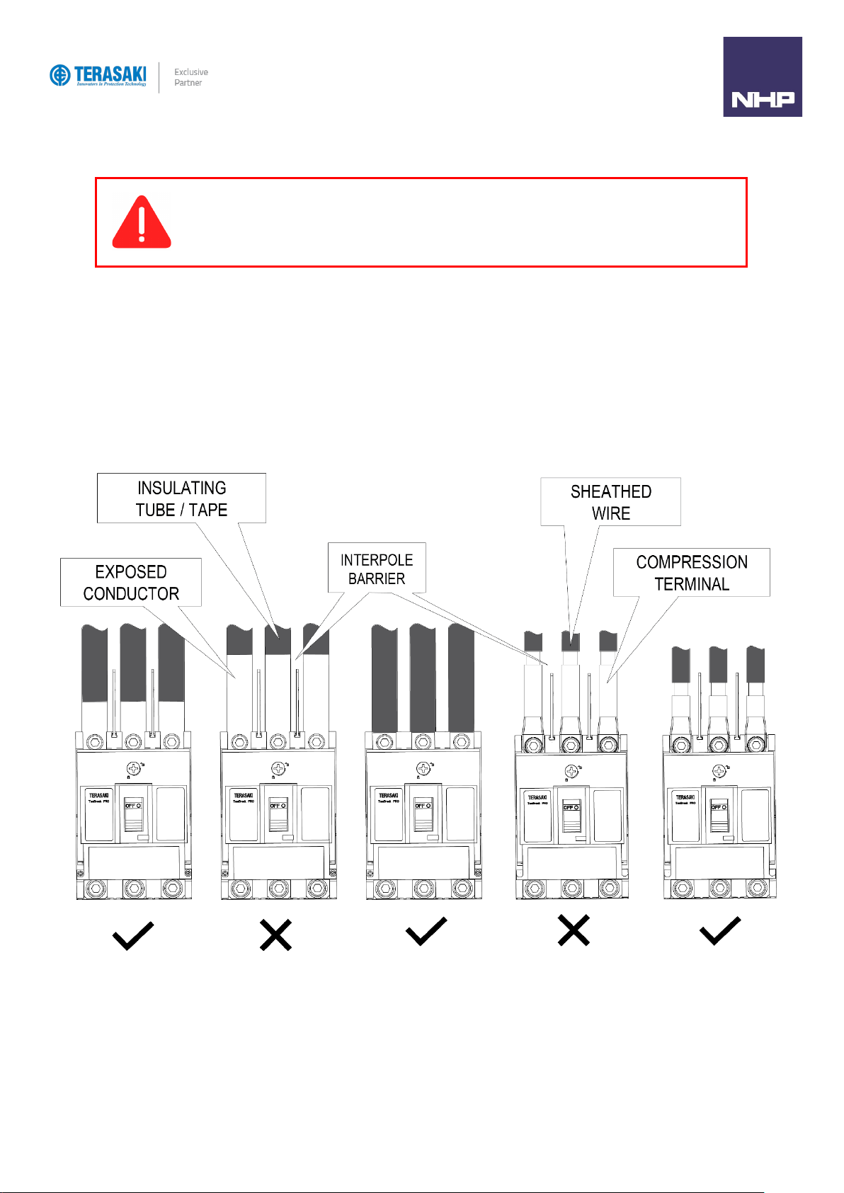
Clearances
Phase to Phase and Earth
Interruption of large currents during fault or normal switching operation produces ionised gases and arcing materials which expelled from the vents at the top
of the MCCB. These ionised gases are highly conductive, concentrated, and at an elevated temperature when it exits the MCCB via the arc vents. Care
must be taken to avoid an arcing fault from occurring due to the presence of concentrated ionised gases creating a conductive path between exposed
conductors. Incoming conductors must therefore be insulated the full length up to the terminal opening of the MCCB, ensuring bare conductors are not
exposed directly to concentrated ionised gases. This also applies to the attached busbars supplied as part of the MCCB.
Interpole barriers or terminal covers may be used to achieve creepage and clearance requirements. Conductors must not impede the flow of ionised gas
and allow it to clear and disperse safety. Interpole barriers are supplied as standard with Terasaki MCCBs for the line side only. 2 barriers with 3P MCCBs
and 3 with 4P MCCBs. In cases where two different MCCB types are installed one above the other, the insulation distance between the two models should
be as for the lower model.
WARNING: Exposed conductors including terminals at attached busbars must be insulated to avoid possible
short-circuit or earth faults due any foreign matter coming into contact with the conductors.

Installation
18
TemBreak PRO P_BE-UM-001-EN V1.3.0
Insulating Distance
When earth metal is installed within proximity of the breakers, the correct insulating distance must be maintained, (refer to Minimum Clearance).
This distance is necessary to allow the exhausted arc gases to disperse. This could include the mounting plate or side panel within a switchboard.
Minimum Clearance
Below illustrates the minimum clearance that must be maintained.
Dim.
Description
MCCB Cat. No.
Distances (mm)
A
B1
B2
C
D
E
A
Distance from lower breaker to open charging part of terminal on
upper breaker (front connection) or the distance from lower
breaker to upper breaker end (rear connection and plug-in type)
P160F
50
10
10
0
25
^
P160N / H / D
75
45
25
0
25
^
P250F
50
40
30
0
25
^
B1
Distance from breaker end to ceiling (earthed metal)
P250N / H / D
80
80
30
0
25
^
B2
Distance from breaker end to insulator
P400F / N / H / D
100
80
60
0
80
^
C
Clearance between breakers
P400S
120
120
80
0
80
^
D
Distance from breaker side to side plate (earthed metal)
P630F / N / H / D
100
80
60
0
80
^
E
Length of insulation over exposed conductors.
P630S
120
120
80
0
80
^
^ Insulate the exposed conductor until it overlaps the moulded case at the terminal, or the terminal cover.
Installation
19
TemBreak PRO P_BE-UM-001-EN V1.3.0
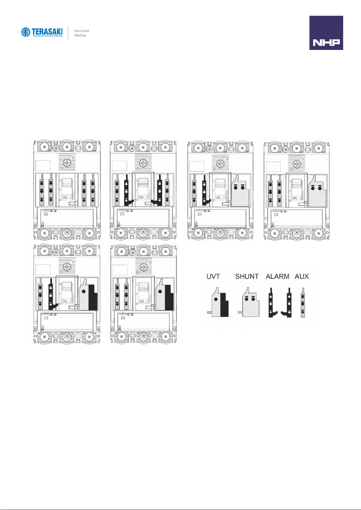
Internal Accessory Mounting Locations
P160, P250 and P400/630 frame sizes have different internal mounting locations for auxiliary contacts, alarm contacts, shunts and, UVTs.
Left-side and right-side mounting locations are independent and accept unique combinations. For example, shunts and UVTs may only be mounted on the
right side, whereas auxiliary and alarm contacts may be mounted on either left or right side.
Refer to the following illustrations for each frame size listing the various possible internal accessories combinations.
P160 internal accessories combination
Legend
Installation
Internal Accessory Mounting Locations
20
TemBreak PRO P_BE-UM-001-EN V1.3.0
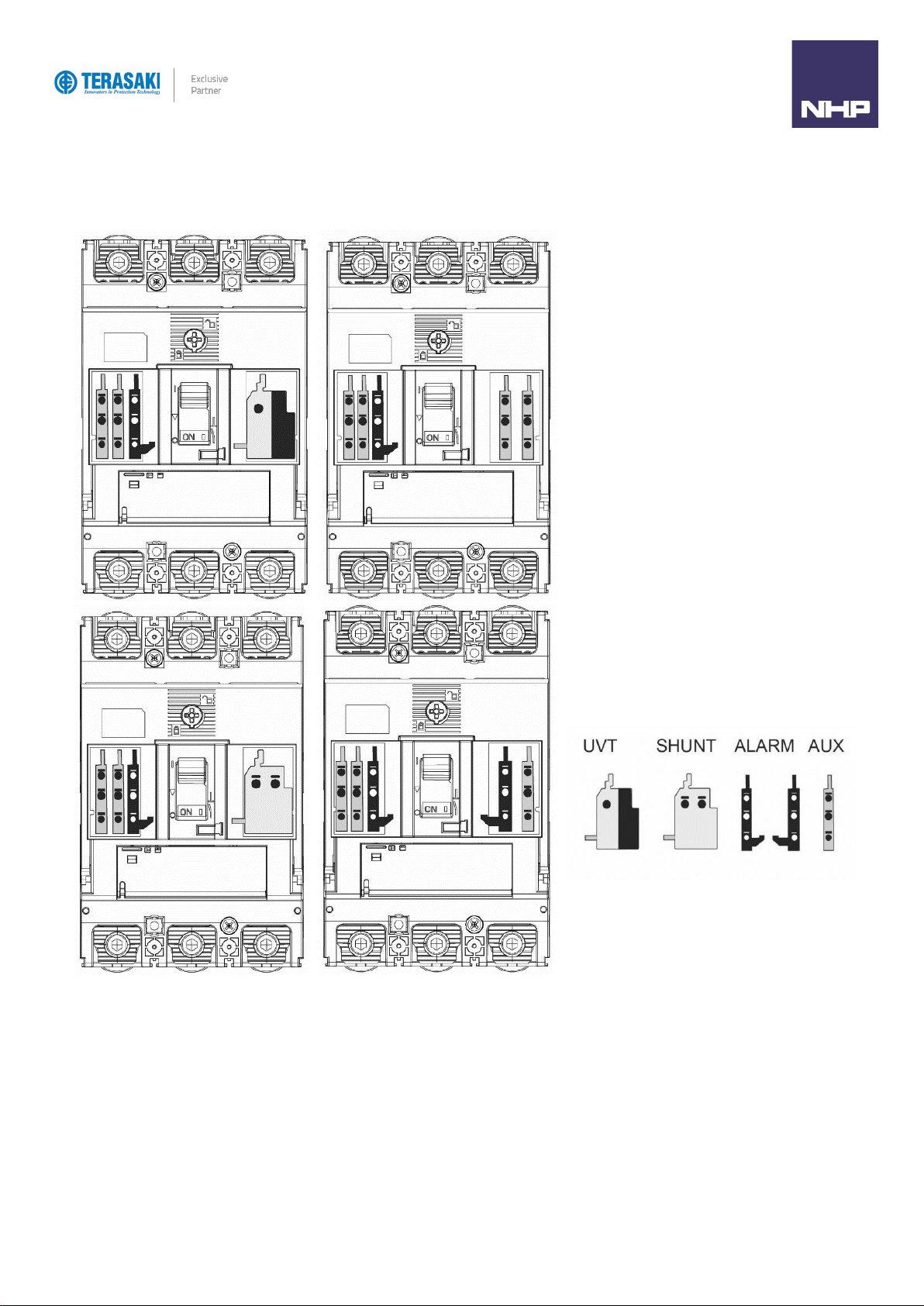
P250 internal accessories combination
Legend
Table of contents
Other NHP Circuit Breaker manuals


Popular Circuit Breaker manuals by other brands

DRIESCHER-WEGBERG
DRIESCHER-WEGBERG VSS Addition to Operation and Assembly Instructions

GE
GE MicroVersaTrip Plus Series user guide

Schrack
Schrack MC1-PN-XPA installation instructions

Eaton
Eaton NOVA LBS 15 Installation and operation instructions

Eaton
Eaton Series NRX Instruction leaflet

ABB
ABB SACE Emax 2 operating instructions


