manuals.online logo
Brands
  1. Home
  2. •
  3. Brands
  4. •
  5. TERASAKI
  6. •
  7. Circuit Breaker
  8. •
  9. TERASAKI TemBreak PRO XDM1 User manual

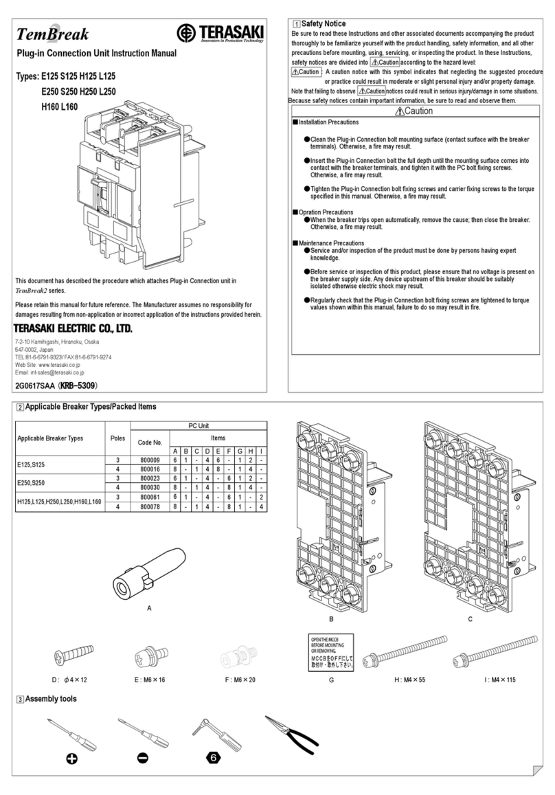
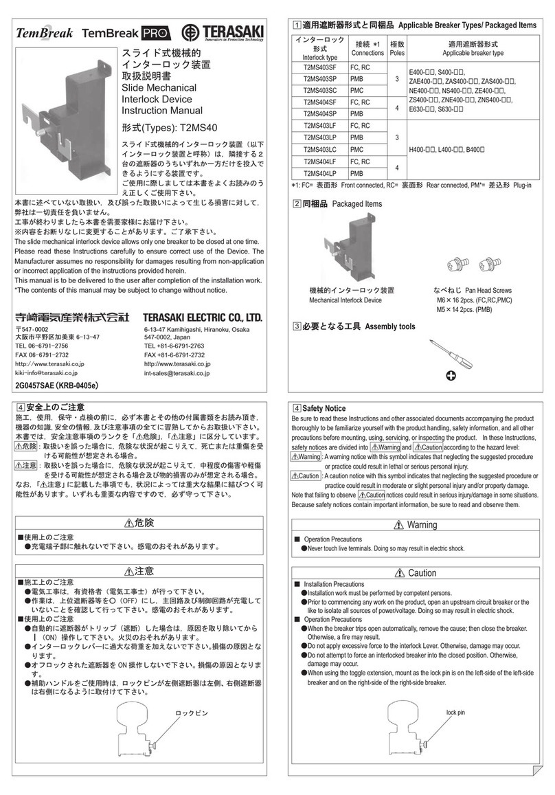
TERASAKI TemBreak PRO XDM1 User manual

差込取付台形式
Plug-in base type
極数
Poles
内容物
Packaged Items
2P
3P
XDM1
数
Qty
数
Qty
内容物
Packaged Items
2 4
4 6
T2PM12E
T2PM12C3P4 6
T2PM12LT
T2PM12LC 3P4 6
T2PM25E
T2PM25C3P4 6
T2PM25LE
T2PM25LC 3P4 6
T2PM40E
T2PM40C3P4 6
T2PM80E
T2PM80C3P4 6
T2PM80M
T2PM80N3P4 6
T2PMX3E
T2PMX3C
3P4 12
4P4 16
M5×25 M6
M5M6
M5M8
M8M10
M10 M16
M10 M12×47
〒547‐0002
大阪市平野区加美東6
–
13
–
47
TEL 06
–
6791
–
2756
FAX 06
–
6791
–
2732
http://www.terasaki.co.jp
[email protected]
2G1023SAC(KRB-0653c)
6
–
13
–
47 Kamihigashi, Hiranoku, Osaka
547-0002, Japan
TEL +81-6-6791-2763
FAX +81-6-6791-2732
http://www.terasaki.co.jp
[email protected]
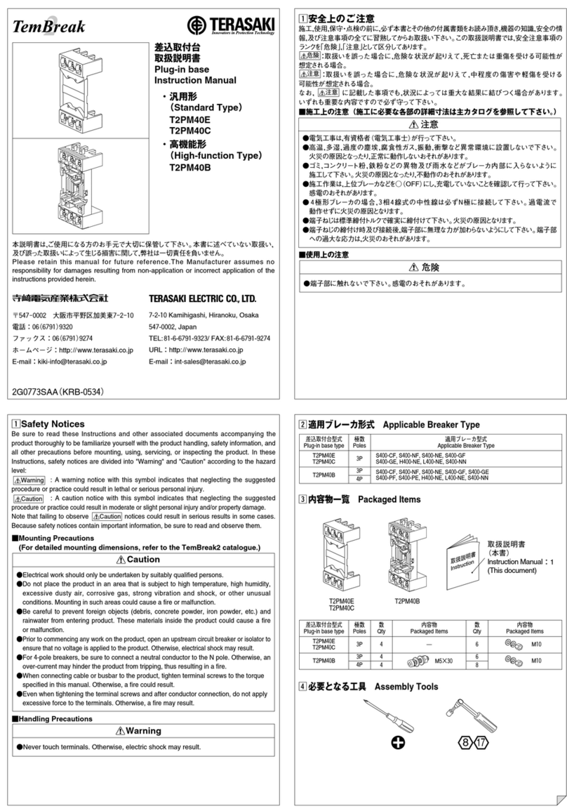
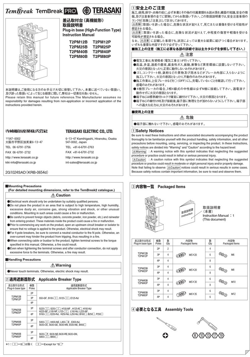
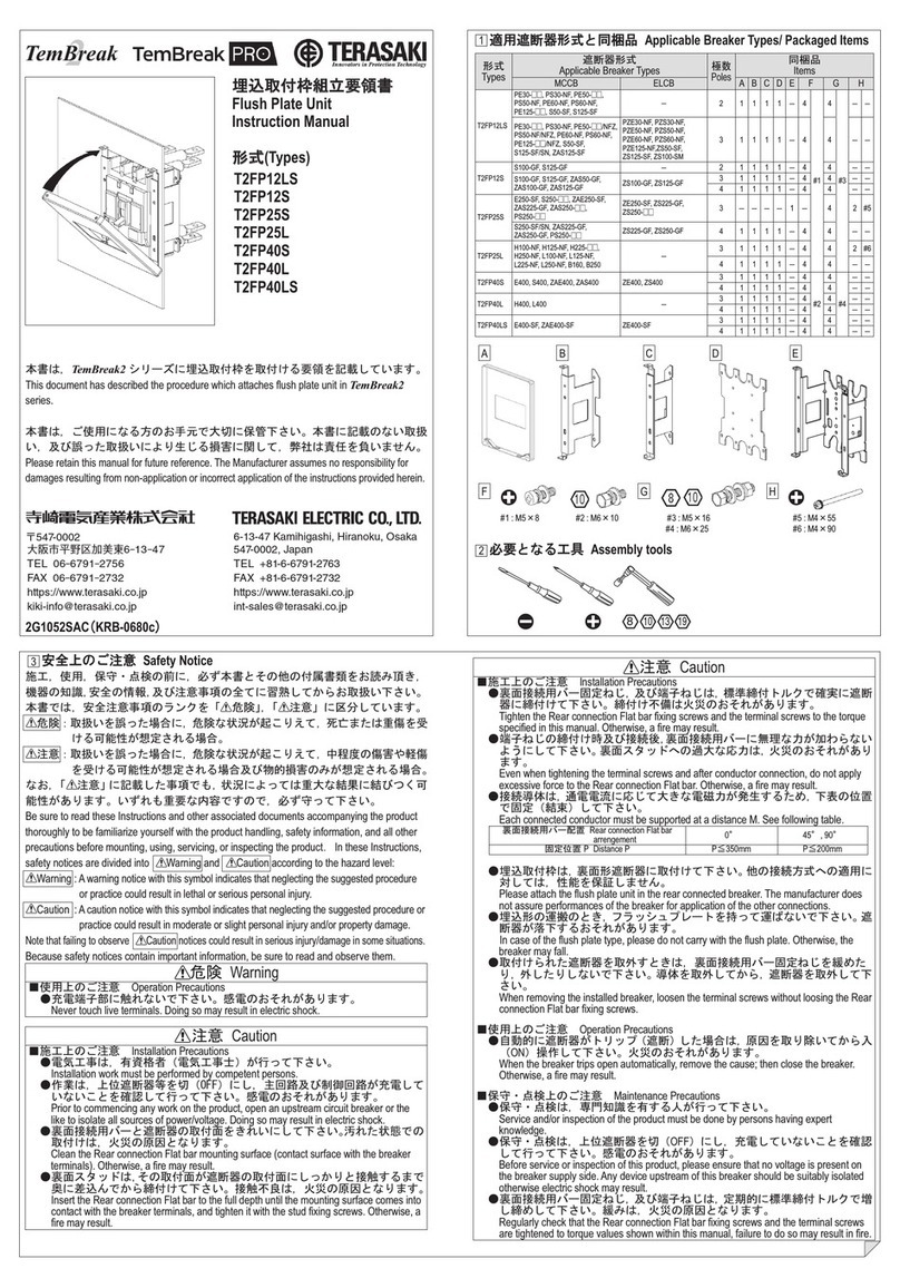
差込取付台
取扱説明書
Plug-in base
Instruction Manual
XDM1
T2PM12E T2PM12C
T2PM12LT T2PM12LC
T2PM25E T2PM25C
T2PM25LE T2PM25LC
T2PM40E T2PM40C
T2PM80E T2PM80C
T2PM80M T2PM80N
T2PMX3E T2PMX3C
x適用遮断器形式 Applicable Breaker Type
c内容物一覧 Packaged Items
v必要となる工具 Assembly Tools
差込取付台形式
Plug-in base type
極数
Poles
適用遮断器形式
Applicable Breaker Type
2P
4P
本説明書は,ご使用になる方のお手元で大切に保管して下さい。本書に述べていない取扱い,
及び誤った取扱いによって生じる損害に関して,弊社は一切責任を負いません。
Please retain this manual for future reference.The Manufacturer assumes no
responsibility for damages resulting from non-application or incorrect application of the
instructions provided herein.
z安全上のご注意
施工,使用,保守・点検の前に,必ず本書とその他の付属書類をお読み頂き,機器の知識,安全の情
報,及び注意事項の全てに習熟してからお取扱い下さい。この取扱説明書では,安全注意事項の
ランクを「危険」,「注意」として区 分してあります。
:取扱いを誤った場合に,危険な状況が起りえて,死亡または重傷を受ける可能性が
想定される場合。
:取 扱 い を 誤 っ た 場 合 に ,危険な状況が起りえて,中程度の傷害や軽傷を受ける
可能性が想定される場合。
なお, に記載した事項でも,状況によっては重大な結果に結びつく場合があります。
いずれも重要な内容ですので必ず守って下さい。
■施工上の注意(施工に必要な各部の詳細寸法は主カタログを参照して下さい。)
●電気工事は,有資格者(電気工事士)が行って下さい。
●高温,多湿,過度の塵埃,腐食性ガス,振動,衝撃など異常環境に設置しないで下さい。
火 災 の 原 因となったり,正常に動作しないおそれがあります 。
●ゴミ,コンクリート粉,鉄粉などの異物及び雨水などがブレーカ内部に入らないように
施工して下さい。火 災 の 原 因となったり,不動作のおそれがあります。
●施工作業は,上位ブレーカなどを○(OFF)にし ,充電していないことを確認して行って下さい。
感電のおそれがあります 。
●4極形ブレーカの場合,3相4線式の中性線は必ずN極に接続して下さい。過電流で
動作せずに火災の原因となります 。
●端子ねじは標準締付トルクで確実に締付けて下さい。火災の原因となります 。
●端子ねじの締付け時及び接続後,端子部に無理な力が加わらないようにして下さい 。端子部
への過大な応力は,火災のおそれがあります。
注意
■使用上の注意
●端子部に触れないで下さい。感電のおそれがあります。
危険
■Mounting Precautions
(For detailed mounting dimensions, refer to the TemBreak2 catalogue.)
●Electrical work should only be undertaken by suitably qualified persons.
●Do not place the product in an area that is subject to high temperature, high humidity,
excessive dusty air, corrosive gas, strong vibration and shock, or other unusual
conditions. Mounting in such areas could cause a fire or malfunction.
●
Be careful to prevent foreign objects (debris, concrete powder, iron powder, etc.) and rainwater
from entering product. These materials inside the product could cause a fire or malfunction.
●
Prior to commencing any work on the product, open an upstream circuit breaker or isolator to
ensure that no voltage is applied to the product. Otherwise, electrical shock may result.
●For 4-pole breakers, be sure to connect a neutral conductor to the N pole. Otherwise, an
over-current may hinder the product from tripping, thus resulting in a fire.
●When connecting cable or busbar to the product, tighten terminal screws to the torque
specified in this manual. Otherwise, a fire could result.
●Even when tightening the terminal screws and after conductor connection, do not apply
excessive force to the terminals. Otherwise, a fire may result.
Caution
■Handling Precautions
●Never touch terminals. Otherwise, electric shock may result.
Warning
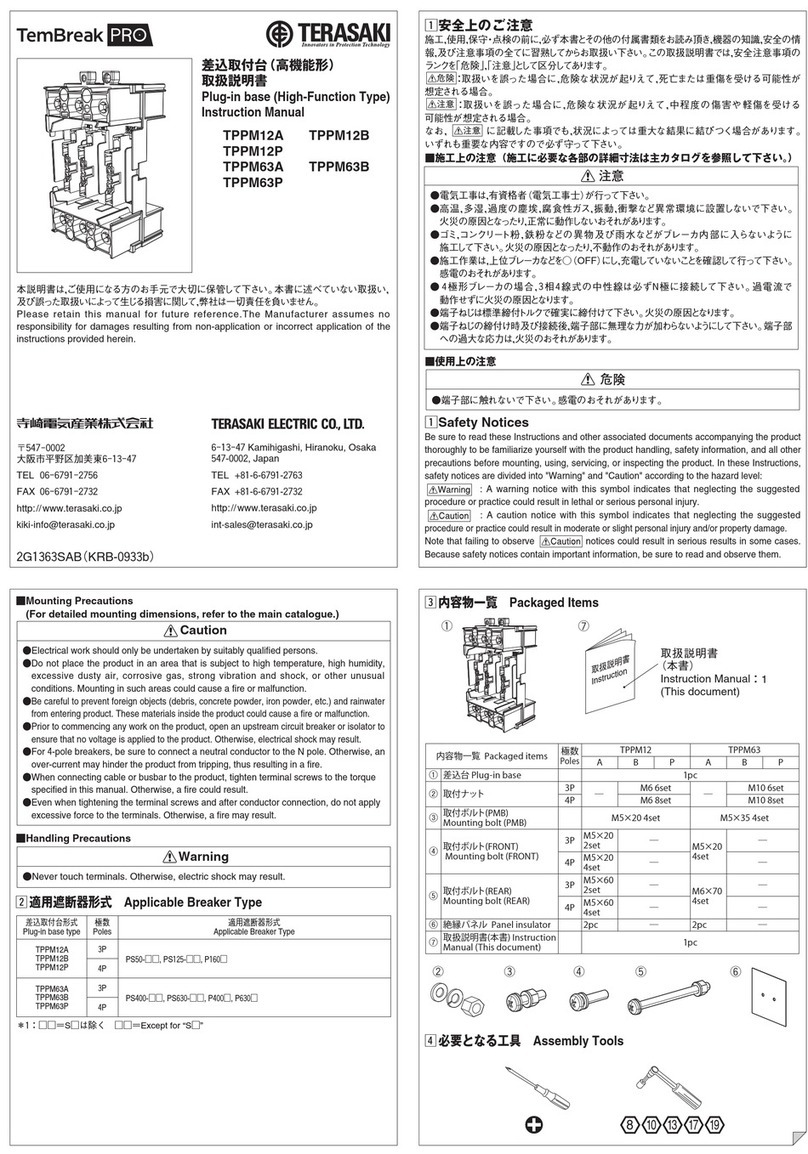
zSafety Notices
Be sure to read these Instructions and other associated documents accompanying the product
thoroughly to be familiarize yourself with the product handling, safety information, and all other
precautions before mounting, using, servicing, or inspecting the product. In these Instructions,
safety notices are divided into "Warning" and "Caution" according to the hazard level:
: A warning notice with this symbol indicates that neglecting the suggested
procedure or practice could result in lethal or serious personal injury.
: A caution notice with this symbol indicates that neglecting the suggested
procedure or practice could result in moderate or slight personal injury and/or property damage.
Note that failing to observe notices could result in serious results in some cases.
Because safety notices contain important information, be sure to read and observe them.
XDM1E50-SF, E50-CM, E100-SF
8
13 17 19 2410
図
Fig.
3P
T2PM12E
T2PM12C3PS50-GF, S100-□□ , S125-□□
T2PM12LT
T2PM12LC 3PS50-SF, S125-S□
T2PM25E
T2PM25C3PS225-□□, S250-□□ , H100-NF , H125-NF,
H225-NF, L100-NF , L125-□F, L225-NF
T2PM25LE
T2PM25LC 3PE250-S□, S250-S□, A250□
T2PM40E
T2PM40C3PS400-□□, H400-NE, L400-□E, B400□
T2PM80E
T2PM80C3PS630-□□, S800-□□, B800□
T2PM80M
T2PM80N3PH630-NE, L630-NE, H800-NE, L800-□E, B800P, B800R
T2PMX3E
T2PMX3C
3PS1250-SE, S1250-□E, B1250□
①
②
取扱説明書
Instruction
:1
取扱説明書
(本書)
Instruction Manual
(This document)
Fig.① Fig.②
*1:裏面スタッドバー付 With flat bar stud for rear connection.
*2:□□=S□は除く □□=Except for “S□”
②*1
A
A2
Fig.① Fig.②
A2
補助回路端子
AuxiliaryCircuitTerminals
T2PM12E
T2PM12C
M6
XDM1
C≦10mm ≦10mm
D6.5mm 6.5mm
F
M6
3.6〜6.0N・m3.6〜6.0N・m
E――
T2PM12LT
T2PM12LC T2PM25E
T2PM25C
T2PM25LE
T2PM25LC
T2PM40E
T2PM40CT2PM80E
T2PM80C
T2PM80M
T2PM80N
T2PMX3E
T2PMX3C
B≦18mm ≦15mm ≦17mm ≦25mm ≦35mm ≦40mm ≦45mm
≦12mm ≦16.5mm ≦20mm ≦26.5mm ≦30mm
6.5mm 9mm 11mm 17mm 13mm×2
(Pitch 36mm ±4)
―≦16.5mm ―――
M6M8M10 M16 M12×47
3.6〜6.0N・m8.8〜14.7N・m18.6〜29.4N・m51.5〜84.3N・m40.2〜65.7N・m
10 10 10 13 17
24 19
b差込取付台取付要領 Plug-in Base Mounting Procedure
補助回路端子標準配列 Standard arrangement for plug-in type auxiliary circuit terminals
AM5×25
2P
XDM1 T2PM12E
T2PM12LT
T2PM25E
T2PM25LE
T2PM12C
T2PM12LC
T2PM25C
T2PM25LC
T2PM40E T2PM40C T2PM80E
T2PM80M
T2PMX3E
T2PM80C
T2PM80N
T2PMX3C
3P 3P 3P 3P, 4P
AXc1 AXa1 AXb1 AXc1 AXa1 AXb1 U1 U2 AXc1 AXa1 AXb1 C1 C2 C1 C2AXc1 AXa1 AXb1 AXc2 AXa2 AXb2
AXc1 AXa1 AXb1 D1 D2
AXc1 AXa1 AXb1 ALc1 ALa1
AXc1 AXa1 AXb1 P1 P2
AXa1 AXb1 P1 P2
AXc1 AXa1 AXb1 S1 S2
ALc1 ALa1 ALb1 ALc1
ALc1
ALa1 ALb1 U1 U2 ALc1 ALa1 ALb1 C1 C2
ALc1 ALa1 ALb1 D1 D2
ALc1 ALa1 ALb1 S1 S2
U1 U2
P1 P2
S1 S2
D1 D2AXc1 AXa1 AXb1 ALc1 ALa1 ALb1 OP1 OP2
AXc2 AXa2 AXb2 PALc PALa
C1 C2AXc1 AXa1 AXb1 ALc1 ALa1 ALb1 OP1 OP2
AXc2 AXa2 AXb2 PALc PALa
D1 D2AXc1 AXa1 AXb1 AXc2 AXa2 AXb2
D1 D2AXc1 AXa1 AXb1 ALc1 ALa1 ALb1
C1 C2AXc1 AXa1 AXb1 PALa PALb OP1 OP2
C1 C2AXc2 AXa2 AXb2 ALc1 ALa1 ALb1
※2
※2
※1
※1
※2
2.2〜3.5N・m
A2
n導体接続要領
Coductor Connection Procedure
φD
φD
B
C
B
E
F
M5
8
A2
M5
M8
M10
AM5×25 2.6〜3.5N・m
2.6〜3.5N・m
8
11.8〜14.7N・m
13
22.6〜30.0N・m
17
※1:OCRコントローラが別置の場合、OP1、OP2端子はOS1、OS2端子に置き換え同番号のコントローラ端子と結線してください。
※2:UVTコントローラが別置の場合、P1、P2端子はUC1、UC2端子に置き換えコントローラのUC1、UC2端子と結線してください。
✽1:If the OCR controller is installed separately, substitute OS1and OS2for OP1and OP2and connect these terminals to the controller terminals having the same numbers.
✽2:If the UVT controller is installed separately, substitute UC1and UC2for P1and P2and connect these terminals to the controller terminals having the same numbers.
2G1023SAC(KRB-0653c)

This manual suits for next models

16

Other TERASAKI Circuit Breaker manuals

TERASAKI TemBreak PRO T2FP12LS User manual

TERASAKI

TERASAKI TemBreak PRO T2FP12LS User manual

TERASAKI TemPower2 AR-E Series User manual

TERASAKI

TERASAKI TemPower2 AR-E Series User manual

TERASAKI TemBreak 2 User manual

TERASAKI

TERASAKI TemBreak 2 User manual

TERASAKI AME Series User manual

TERASAKI

TERASAKI AME Series User manual

TERASAKI TemBreak 2 T2PM12B User manual

TERASAKI

TERASAKI TemBreak 2 T2PM12B User manual

TERASAKI TemBreak PRO TPPM12A User manual

TERASAKI

TERASAKI TemBreak PRO TPPM12A User manual

TERASAKI TemBreak 2 E125 User manual

TERASAKI

TERASAKI TemBreak 2 E125 User manual

TERASAKI TemBreak PRO T2MS4 User manual

TERASAKI

TERASAKI TemBreak PRO T2MS4 User manual

TERASAKI TemPower 2 ACB User manual

TERASAKI

TERASAKI TemPower 2 ACB User manual

TERASAKI NHP TemBreak PRO P160 Series User manual

TERASAKI

TERASAKI NHP TemBreak PRO P160 Series User manual

TERASAKI TemPower 2 User manual

TERASAKI

TERASAKI TemPower 2 User manual

Popular Circuit Breaker manuals by other brands

Allen-Bradley 194E installation instructions

Allen-Bradley

Allen-Bradley 194E installation instructions

Mitsubishi Electric NF400-SEW instruction manual

Mitsubishi Electric

Mitsubishi Electric NF400-SEW instruction manual

LEGRAND DPX 3 1600 manual

LEGRAND

LEGRAND DPX 3 1600 manual

Siemens GMI Series Instruction

Siemens

Siemens GMI Series Instruction

Eaton P5-125/Z Instruction leaflet

Eaton

Eaton P5-125/Z Instruction leaflet

Eaton mRBM4-PT Instruction leaflet

Eaton

Eaton mRBM4-PT Instruction leaflet

GenInterlock SIE-V2 MIRROR instructions

GenInterlock

GenInterlock SIE-V2 MIRROR instructions

Eaton FRCdM-Type B Instruction leaflet

Eaton

Eaton FRCdM-Type B Instruction leaflet

ABB GE Power Break II installation instructions

ABB

ABB GE Power Break II installation instructions

Kohler 31613437101NE manual

Kohler

Kohler 31613437101NE manual

Siemens 3AH35-SE Series instruction manual

Siemens

Siemens 3AH35-SE Series instruction manual

OEZ BD250NE305 Instructions for use

OEZ

OEZ BD250NE305 Instructions for use

Siemens 3VT9100-8CE00 operating instructions

Siemens

Siemens 3VT9100-8CE00 operating instructions

Eaton AFDD+ Instruction leaflet

Eaton

Eaton AFDD+ Instruction leaflet

OEZ LTS Instructions for use

OEZ

OEZ LTS Instructions for use

Siemens MBKJD1A installation instructions

Siemens

Siemens MBKJD1A installation instructions

OEZ LVN-XC Instructions for use

OEZ

OEZ LVN-XC Instructions for use

ABB SACE Emax 2 E2.2 manual

ABB

ABB SACE Emax 2 E2.2 manual

manuals.online logo
manuals.online logoBrands
  • About & Mission
  • Contact us
  • Privacy Policy
  • Terms and Conditions

Copyright 2025 Manuals.Online. All Rights Reserved.