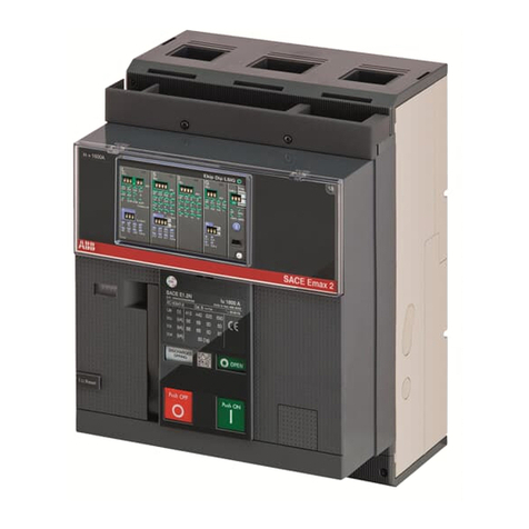
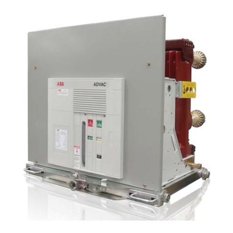
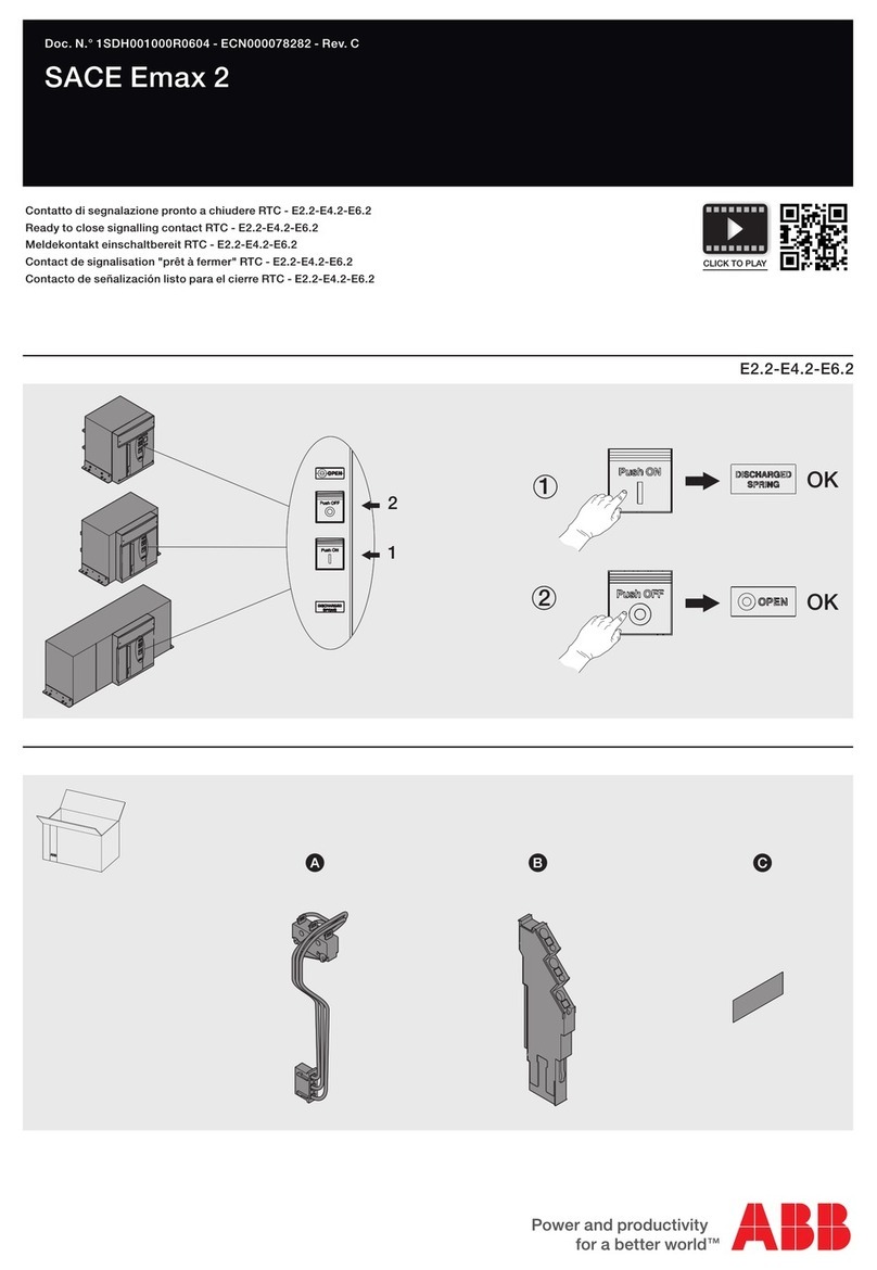
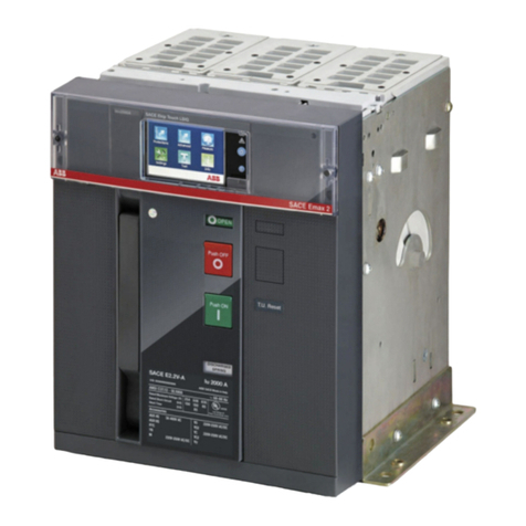
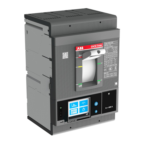
ABB SACE Emax 2 User manual

SACE Emax 2
DOC. N° 1SDH001330R1002 - ECN000297030
EN
LOW VOLTAGE AIR CIRCUIT-BREAKERS EMAX E1.2-E2.2-E4.2-E6.2
SACE Emax 2
Operating instructions for the design engineer
SACE Emax 2
DOC. N° 1SDH001330R1002 - ECN000297030

ABB | SACE Emax 2ABB | SACE Emax 2
© 2023 ABB | 1SDH001330R1002 - ECN000297030

1SDH001330R1002 - ECN0002970301 | © 2023 ABB | SACE Emax 2
Contents
Glossary .................................................................................................3
Circuit-breakers E1.2-E2.2-E4.2-E6.2................................................. 4
1 - Introduction................................................................................4
2 - Safety...........................................................................................6
3 - Environmental conditions .......................................................7
4 - Guide to the product choice...................................................9
5 - Selectivity between ABB SACE circuit-breakers ...............13
6 - Documents and Tools for the design engineer.................14
Trip unit Overview ..............................................................................17
1 - General characteristics .......................................................... 17
2 - Ekip Touch models and versions..........................................18
3 - Accessories and software .....................................................19
4 - Operating features ................................................................ 20
Ekip Dip................................................................................................21
1 - Operator interface ..................................................................21
2 - Protections - Introduction.....................................................23
3 - Measurements........................................................................ 30
4 - Test ............................................................................................ 31
5 - List of alarms and signals .....................................................32
6 - Additional functions.............................................................. 34
7 - Default parameters.................................................................37
Ekip Touch - Interface and menus.................................................... 38
1 - Presentation of interface...................................................... 38
2 - Navigation ............................................................................... 40
3 - Graphic pages......................................................................... 42
4 - Menu......................................................................................... 46
5 - Changing parameters and commands...............................51
6 - PIN and security ......................................................................53
Ekip Touch - Protections................................................................... 54
1 - Protections - Introduction.................................................... 54
2 - Standard Protections............................................................ 55
3 - Voltage protections............................................................... 65
4 - Voltage Advanced protections............................................ 68
5 - Frequency protections...........................................................72
6 - Power protections ..................................................................75
7 - ROCOF protections.................................................................81
8 - Protection Adaptive .............................................................. 82
9 - Additional protections and functions ............................... 83
10 - Logic selectivity.....................................................................93
11 - Performance table................................................................ 95
12 - Functions ............................................................................... 98
Ekip Touch - Measurements ............................................................113
1 - Standard Measurements ..................................................... 113
2 - Measuring Measurements................................................... 117
3 - Class 1 Power & Energy Metering...................................... 120
4 - Datalogger ............................................................................. 121
5 - Network Analyzer..................................................................123
Ekip Touch - Settings ...................................................................... 130
1 - Main settings ........................................................................ 130
2 - Additional settings ...............................................................134
Ekip Touch - Test.............................................................................. 136
1 - Test...........................................................................................136
Ekip Touch - Additional functions ................................................. 138
1 - Zone Selectivity .....................................................................138
2 - Generator protection ...........................................................141
3 - Power Controller....................................................................142
4 - Load Shedding ......................................................................143
5 - IPS Interface protections.................................................... 145
Ekip Touch - Default .........................................................................147
1 - Ekip TOUCH default parameters........................................147
Mechanical characteristics............................................................. 148
1 - E1.2 description .................................................................... 148
2 - E2.2-E4.2-E6.2 description...................................................156
3 - Installation..............................................................................166
4 - Technical characteristics..................................................... 174
Accessories........................................................................................176
1 - Overview..................................................................................176
2 - Standard accessories .......................................................... 180
3 - Assembly and disassembly .................................................181
Mechanical accessories................................................................... 183
1 - Mechanical Protection accessories ...................................183
2 - Mechanical safety accessories ...........................................185
3 - Mechanical Interlocks.......................................................... 190
4 - Lifting plates..........................................................................191
Electrical accessories.......................................................................192
1 - Electrical control accessories .............................................192
2 - Electrical signalling accessories ........................................196
Internal electronic accessories ......................................................204
1 - Rating Plug.............................................................................204
2 - Measurement ........................................................................ 205
3 - Ekip Signalling 4K ................................................................ 208
4 - Ekip LCD.................................................................................. 211
External electronic accessories ......................................................212
1 - Ekip Supply .............................................................................212
2 - Ekip Com Modbus RTU ........................................................213
3 - Ekip Com Profibus DP ..........................................................216
4 - Ekip Com DeviceNet TM .........................................................219
5 - Ekip Com Modbus TCP.........................................................222
6 - Ekip Com Profinet................................................................ 226
7 - Ekip Com EtherNet/IP TM ..................................................... 229
2 | © 2023 ABB | SACE Emax 2 1SDH001330R1002 - ECN000297030
8 - Ekip Com IEC 61850..............................................................232
9 - Ekip Link ................................................................................ 236
10 - Ekip Com Hub ..................................................................... 240
11 - Ekip Signalling 2K ...............................................................244
12 - Ekip Synchrocheck ..............................................................247
13 - Ekip Signalling 3T ............................................................... 253
Other electronic accessories.......................................................... 256
1 - Ekip Signalling 10K............................................................... 256
2 - Ekip Signalling Modbus TCP .............................................. 256
3 - Ekip Multimeter.....................................................................257
4 - Rc Toroid.................................................................................257
5 - S.G.R. Toroid...........................................................................257
6 - External neutral.................................................................... 258
7 - Ekip Com Actuator............................................................... 258
8 - Ekip AUP ................................................................................ 258
9 - Ekip RTC................................................................................. 258
10- Testing and Programming................................................ 259
Putting into service and maintenance .......................................... 261
1 - Putting into service...............................................................261
2 - Maintenance.......................................................................... 266
3 - E1.2 maintenance and E2.2, E4.2 and E6.2 first level
maintenance............................................................................... 268
4 - E2.2, E4.2 and E6.2 second level maintenance ................274
5 - Lubrication of jaw-type isolating contacts of withdrawable
circuit-breaker............................................................................ 283
Alarms or failures............................................................................. 285
1 - Identification of alarms or failures ................................... 285
2 - Self-diagnosis........................................................................291
Predictive analysis program........................................................... 294
1 - Presentation.......................................................................... 294
2 - Service offers........................................................................ 295
Decommissioning and treatment at end of life........................... 296
1 - Decommissioning and treatment at end of life ............. 296
Service............................................................................................... 297
1 - Power Care............................................................................. 297

ABB | SACE Emax 2ABB | SACE Emax 2
3 | © 2023 ABB | 1SDH001330R1002 - ECN000297030

ABB | SACE Emax 2ABB | SACE Emax 2
Glossary3 | © 2023 ABB | 1SDH001330R1002 - ECN000297030
Glossary
Term Description
SACE Emax 2 New series of ABB SACE air circuit-breakers
CB Circuit-breaker
Protection release Electronic unit connected to the CB (Mainboard), which provides measuring, monitoring and protection
functions for the CB if faulty operating conditions occur. In the event of an alarm, it commands a TRIP
Trip unit Protection release
Mainboard Electronic board of the CB to which the Trip Unit and all the main accessories and electronic actuators
connect
Ekip Touch Trip unit for SACE Emax 2 CBs, equipped with touchscreen display and available in four different versions
Ekip Dip Trip unit SACE Emax 2 CBs, equipped with dip-switch type interface
Ekip LCD Trip unit for SACE Emax 2 CBs, equipped with LCD display; alternative to Ekip Touch for applications in
particular environmental conditions
Trip coil CB opening actuator controlled directly by Trip unit
TRIP
Concluding action of protection timing or a test command which, except in special configurations applicable
to the trip unit, coincides with activation of the trip coil, which instantly opens the bars of each pole and
interrupts the circulating current
Vaux Auxiliary power supply
4P / 3P / 3P + N CB configuration: four-pole (4P), three-pole (3P) and three-pole with external neutral (3P + N)
If Fault current measured by Trip unit, useful for calculating the trip time t t

ABB | SACE Emax 2
Circuit-breakers E1.2-E2.2-E4.2-E6.2
1 - Introduction
4 | © 2023 ABB | 1SDH001330R1002 - ECN000297030
Circuit-breakers E1.2-E2.2-E4.2-E6.2
1 - Introduction
Foreword
SACE Emax 2 is the new series of low voltage air circuit-breakers up to 6300 A, designed for managing
all low voltage electrical installations with the maximum efficiency: from industrial installations, marine
applications, conventional power generation and renewable energy installations, to buildings, malls, data
centers and communication networks.
Overview
This manual contains all the useful information for:
• Facilitating the choice of the product and of the features required.
• Rapid access to all the necessary information for proper design.
• Proper use of all the features available with the solid-state protection trip units.
• All the supporting documentation.
• Link to management software.
recipients
This manual refers to two user profiles, as defined by standard IEC 60050:
• skilled person, in the electrical field (IEV 195-04-01): person with sufficient training and experience
to enable him or her to perceive risks and avoid the dangers potentially created by electricity)
• instructed person, in the electrical field (IEV 195-04-02): person adequately advised or supervised
by electrically skilled persons to enjable him or her to perceive risks and to avoid danger which
electricity can create
IMPORTANT: operations which can be performed by persons trained on the subject of
electricity are specifically indicated in this manual. All the remaining operations described
in this manual must be performed by skilled persons, in the field of electricity. ABB
declines all liability for damage to persons or property caused by failure to comply with
the instructions in this document.
Specifications and supporting
documents
To ensure that the Emax 2 circuit-breaker is installed and configured correctly, please read the information
in this manual and in the technical documentation of the product, supplied with the circuit-breaker or
available in the website ABB liBrAry
Document Description
1SDH000999R0002 Installation, operation and maintenance instructions for Sace Emax E1.2
CBs and Ekip Dip Trip units
1SDH001000R0002 Installation, operation and maintenance instructions for Sace Emax E2.2-
E4.2-E6.2 CBs and Ekip Dip Trip units
1SDH001316R1002 Manual of Ekip Touch Trip units for Sace Emax 2 CBs
1SDH001140R0001 Communication System Interface for Emax 2 CBs
1SDC200023D0906 Sace Emax 2 CBs General catalog
1SDM000091R0001 Sace Emax 2 CBs Circuit diagrams
Design notes
The information in this manual was written in Italian and then translated into other languages to conform
to the laws and/or commercial requirements concerning the product.

ABB | SACE Emax 2
Circuit-breakers E1.2-E2.2-E4.2-E6.2
1 - Introduction
5 | © 2023 ABB | 1SDH001330R1002 - ECN000297030
Regulations
Emax 2 circuit-breakers and their accessories comply with the following international standards:
• IEC 60947
• EN 60947
• CEI EN 60947
• IEC 61000
• UL 1066
They comply with the following EC directives:
• "Low Voltage Directives" (LVD) No. 2006/95/EC
• "Electromagnetic Compatibility Directive" (EMC) No. 2004/108/EC
Emax 2 circuit-breakers also feature a range certified according to these standards:
• Russian - GOST (Russia Certificate of Conformity)
• Chinese - China CCC (China Compulsory Certification)

ABB | SACE Emax 2
Circuit-breakers E1.2-E2.2-E4.2-E6.2
2 - Safety
6 | © 2023 ABB | 1SDH001330R1002 - ECN000297030
2 - Safety
Warnings
HAZARD
ACCIDENTAL CONTACT WITH LIVE POINTS
CAN CAUSE SHOCK, BURNS AND RESULT
IN DEATH.
Do not try to use the product in any way, before having
read this instruction manual
Figure 1
The following warnings must be respected:
• READ THE INSTRUCTIONS CAREFULLY BEFORE TRYING TO INSTALL, OPERATE OR REPAIR THE
CIRCUIT BREAKER.
• Store these instructions along with other documents for instruction, maintenance and installation,
drawings and descriptive notes on the circuit-breaker.
• Keep these documents available during the installation, operation and maintenance of the appliance.
The use of these instructions facilitates proper maintenance.
• install the circuit-breaker within the limits of the project described in the instruction manual
shipped with the unit. These circuit-breakers are designed to operate with values of voltage and
current within the limits of plate ratings. Do not install this equipment in systems operating at
nominal values exceeding these limits.
• follow the safety procedures indicated by Your Company.
• Do not open any covers or doors, do not work on devices before removing power from all circuits,
and after making sure of that with a measuring instrument.
WARNING!
• Detailed descriptions of standard procedures for installation, use, maintenance and principles
for safe operation are not included. It is important to note that this document contains safety
instructions and caution against certain methods (installation, operation and maintenance) that
could cause injury to personnel, damage equipment, or make them unsafe.
• these warnings and alarms do not include all the conceivable methods of performing the installation,
operation and maintenance operations recommended by ABB and others, which could be performed,
or the possible consequences and complications of each conceivable method, neither will ABB
investigate all those methods.
• anyoneusingmaintenanceproceduresordevices, recommendedbyABBor not, mustcheckthoroughly
that neither personal safety nor the safety devices are endangered by mode of installation, use,
maintenance or the instruments used. For more information, questions or specific problems contact
your nearest ABB representative.
• This manual is written for qualified personnel only and is not intended as a substitute for a proper
course, or experience about safety procedures for this device.
• regarding products equipped with communication systems, the purchaser, installer or end customer
are responsible for applying all the IT security measures to prevent risks deriving from connection
to communication networks; among others, these risks include use of the product by unauthorized
persons, alteration of its normal operation, access to and modification of the information.
• the purchaser, installer or end customer are responsible for ensuring that safety warnings and
notices are affixed and moreover, that all points of access and operating devices are securely
blocked when the switchgear is left even momentarily unattended.
• all the information contained in this document reflects the latest product information available
at the time of printing. We reserve the right to edit the document at any time and without notice

ABB | SACE Emax 2
Circuit-breakers E1.2-E2.2-E4.2-E6.2
3 - Environmental conditions
7 | © 2023 ABB | 1SDH001330R1002 - ECN000297030
3 - Environmental conditions
Installation environment
Install the circuit-breaker in a dry environment, without dust or corrosive acids, and so that it is not subject
to shock or vibration.
If this is not possible, mount the circuit-breaker in a compartment protecting it adequately.
For the dimensions to be considered for installation, see the chapter "3 - Installation" on page 166 where
the references for following information can be found:
• minimum installation volumes of the circuit-breakers and derived versions in a cell
• overall dimensions of the circuit-breakers and the fixed parts
• drilling of mounting holes
• drilling of the cell door
Temperatures of the
installation environment
The mechanical and electrical characteristics are guaranteed between -25 ° C and +70 ° C, -13 °F e +158 °F.
Particular weather conditions
The circuit breaker is designed to operate in particularly difficult industrial environments.
It was tested according to:
• IEC 60068-2-1: endurance at low temperatures
• IEC 60068-2-2: hot dry climate
• IEC 60068-2-30: hot humid climate
• IEC 60068-2-52 severity 2: saline mist atmosphere
• IEC 60947 (pollution level ≤ 3)
• IEC60721-3-6 class 6C3
• IEC60721-3-3 class 3C2
NOTE:
the circuit-breaker is suitable for installation in environments with saline concentrations
no higher than 10 mg/m3.
Dusty environments
It is recommended to install the circuit breaker in suitably ventilated switchgear where penetration by
dust is minimized.
In case of dusty environments (dust> 1 mg/m3) second level maintenance procedures must be followed.
Vibration
The circuit-breaker is insensitive to mechanical or electromagnetic vibrations that meet the following
standards:
• IEC 60068-2-6
a) From 1 to 13 Hz with movement equal to 1 mm - 0.04 in b) From 13 to 100 Hz with
constant acceleration equal to 0.7 g - 0.025 lbs
• Shipping Registers' specifications: RINA, BV, GL, ABS, LRs, DNV

ABB | SACE Emax 2
Circuit-breakers E1.2-E2.2-E4.2-E6.2
3 - Environmental conditions
8 | © 2023 ABB | 1SDH001330R1002 - ECN000297030
Altitude
The circuit breaker maintains its rated operating characteristics up to 2000 m above sea level.
Once this altitude is passed, you need to consider reduction of dielectric strength and reduced cooling
capacity of the air.
The following are the corrections expressed as a percentage to be applied to the parameters according
to altitude:
Altitude 2000 m /
6600 ft
3000 m /
9900 ft
4000 m /
13200 ft
5000 m /
16500 ft
Rated service voltage (V) Ue 100% 88% 78% 68%
Rated current (A) at 40°C 100% 98% 93% 90%
Electromagnetic compatibility
The use of specific devices in industrial installations may cause electromagnetic interference in the
electrical system.
The SACE Emax 2 circuit-breakers were developed and tested in an EMC environment in accordance with
IEC 60947-2, Annex J and F.
Storage Environment
Store the circuit breaker in a dry, dust-free environment free of harsh chemicals.
The storage ambient temperature must be:
• Circuit-breaker in the original packaging, without protection trip unit or Ekip Dip trip unit, between
-40 ° C and +85 ° C, -40 °F e +185 °F.
• Circuit-breaker in the original packaging, with Ekip Touch protection trip unit, between -25°C and
+ 85°C, -22°F e +185°F.
NOTE:
the storage conditions may differ from the usage conditions.

ABB | SACE Emax 2
Circuit-breakers E1.2-E2.2-E4.2-E6.2
4 - Guide to the product choice
9 | © 2023 ABB | 1SDH001330R1002 - ECN000297030
4 - Guide to the product choice
Foreword
The circuit-breaker must check and protect , in case of failure and malfunction, the installation components
that are connected to it. To perform this function, Emax 2 circuit-breakers offer a series of options, that
can be selected by the user according to the particular requirements of the installation.
For a good design, the main characteristics the components must be selected with the greatest care.
In order to help the design engineers in selecting the Emax2 circuit-breakers, a sheet is provided below
containing the main selection criteria for air circuit-breakers. This sheet can be completed (in whole or in
part) by the design engineer to guide subsequent design choices and can be used by the client for work
contracts. Besisdes, this sheet is a useful tool for rapid configuration in CAT selection software.
Device
Type of device
Circuit-breaker
Switch-disconnector
Standard
Reference standard
IEC (EN 60947-2)
UL (UL 1066-ANSI C37.50)
Mechanical characteristics
Insulation function
Yes
No
Nº poles
3
4
Installation version
Fixed
Withdrawable
Terminals
Horizontal/Vertical
Spread
Front
Extended front
Spread front
Floor
For 4x240 FcCuAl cable
NOTE:
consult the technical catalog for details about the terminals.

ABB | SACE Emax 2
Circuit-breakers E1.2-E2.2-E4.2-E6.2
4 - Guide to the product choice
10 | © 2023 ABB | 1SDH001330R1002 - ECN000297030
Electrical characteristics
Service rated voltage
400 V AC
415 V AC
500 V AC
525 V AC
690 V AC
______ V AC
Rated uninterrupted current (40°C) (Iu)
100 A 800 A 2500 A
200 A 1000 A 3200 A
250 A 1200 A 4000 A
400 A 1250 A 5000 A
600 A 1600 A 6000 A
630 A 2000 A 6300 A
Ultimate short-circuit breaking capacity (lcu)
42 kA 120 kA
50 kA 130 kA
66 kA 150 kA
85 kA 200 kA
100 KA a ______ V:
Service short-circuit breaking capacity (lcs)
According to the reference standard:______ % of Icu
Admissible rated short-time withstand current (Icw)
Without intentional delay (class A)
With intentional time-delay (category B):
1 s Icw ______ kA
3 s Icw ______ kA
NOTE:
make sure that the combination of all the electrical values selected is available.
Consult
the technical catalog for further details.

ABB | SACE Emax 2
Circuit-breakers E1.2-E2.2-E4.2-E6.2
4 - Guide to the product choice
11 | © 2023 ABB | 1SDH001330R1002 - ECN000297030
Electronic protections
Ekip Dip can be configured with the following protections:
Current protections
Overload (L - ANSI 49)
Time-delayed overcurrent
Instantaneous overcurrent (l - ANSI 50)
Earth fault current (G - ANSI 51N & 50N TD)
Ekip Touch can be configured with the following protections:
NOTE:
the protections are either present by default or must be installed by means of an
additional package, depending on the Trip unit model and version
(consult Trip unit Overview
for details)
Current protections
Overload (L - ANSI 49)
Time-delayed overcurrent
Second time-delayed overcurrent (S2 – ANSI 50TD)
Instantaneous overcurrent (l - ANSI 50)
Earth fault current (G - ANSI 51N & 50N TD)
Zone selectivity for S, I and G protections (ANSI 68)
Directional overcurrent (D – ANSI 67)
Zone Selectivity for D protection (ANSI 68).
Programmable instantaneous overcurrent (2I - ANSI 50)
Earth fault current with external toroid (Gext - ANSI 51G & 50GTD)
Modified differential ground fault (MDGF)
Residual current (Rc – ANSI 64 & 50 NTD)
Current unbalance (IU – ANSI 46)
Voltage controlled overcurrent (S(V) - ANSI 51V)
Second voltage controlled overpower (S2(V) - ANSI 51V)
Voltage protections
Undervoltage (UV - ANSI 27)
Overvoltage (OV - ANSI 59)
Second undervoltage protection (UV2– ANSI 27)
Second overvoltage protection (OV2– ANSI 59)
Voltage unbalance (VU – ANSI 47)
Cyclical direction of the phases (ANSI 47)
Residual overvoltage (RV – ANSI 59N)
Frequency protections
Underfrequency (UF - ANSI 81L)
Overfrequency (OF - ANSI 81H)
Second minimum frequency protection (UF2– ANSI 87L)
Second maximum frequency protection (OF2 – ANSI 87H)
Rate of change of frequency (ROCOF – ANSI 81R)
Power protections
Reverse active power (RP - ANSI 32R)
Power factor (ANSI 78)
Loss of field or reverse reactive power (RQ – ANSI 40 or 32RQ)
Reactive overpower (OQ – ANSI 32OF)
Active overpower (OP – ANSI 32OF)
Active underpower (UP – ANSI 32LF)
Miscellaneous protections
Synchronism between two supply sources - Synchrocheck (SC - ANSI 25)
Interface protections (IPS)

ABB | SACE Emax 2
Circuit-breakers E1.2-E2.2-E4.2-E6.2
4 - Guide to the product choice
12 | © 2023 ABB | 1SDH001330R1002 - ECN000297030
Electrical and mechanical
accessories
Electrical signalling
Open/closed auxiliary contacts - AUX
Ready to close signalling contact - RTC
Ready to close signalling contact Ekip – RTC
Ekip protection trip unit tripping signalling contact – S51
Remote resetting - YR
Service trip units
First and second opening coil - YO
First and second closing coil - YC
Undervoltage coil - YU
Motor operator
Motor
Protections
Protection device for opening and closing push buttons - PBC
Compartment door flange
Terminal-covers and separators
High terminal-covers - HTC
Low terminal-covers - LTC
Phase separators PB
Other accessories
mechanical operation counter - MOC
NOTE:
for full details on Emax 2 electrical and mechanical accessories see chapter “
Electrical
accessories
” starting on page
192.
Electronic accessories
Measurement Module - Protection and measurements of voltage, power and energy
Ekip Signalling 10K/ 4K/ 2K/ 3T/ Modbus TCP - Programmable input and output contacts
Ekip Supply - Power supply for trip units and modules
Ekip COM - Communication with multiple protocols
Ekip Synchrochek - Synchronism between two power supply sources
Ekip Multimeter - Power supply and measurements from switchgear front
Ekip LCD - Interface with LCD display for particular environmental conditions
NOTE:
for full details on Emax 2 electronic accessories see chapter “
Accessories
” starting
on page
176.

ABB | SACE Emax 2
Circuit-breakers E1.2-E2.2-E4.2-E6.2
5 - Selectivity between ABB SACE circuit-breakers
13 | © 2023 ABB | 1SDH001330R1002 - ECN000297030
5 - Selectivity between ABB SACE circuit-breakers
Foreword
It is possible to obtain selectivity between ABB SACE circuit-breakers (including Emax 2).
There is selectivity in an installation when, in the event of an overload or short-circuit, it is possible to
identify and isolate the point of overload or fault by opening only some circuit-breakers to guarantee
service continuity to the installation.
NOTE:
selectivity is recommended in all installations with multiple switchgears or circuit-
breakers connected, for example cascading or in a tree (with a main circuit-breaker on the
supply side, and other circuit-breakers downstream to protect areas on the other side).
Thus, only the circuit-breaker immediately upstream the overload or fault trips, and avoids
opening of the circuit-breakers further upstream.
Types of selectivity
With ABB SACE electronic trip units selectivity can be:
• Current-based selectivity, activated in the event of over-current, and in which the protections of
the trip units are set with different current thresholds, based on the principle the closer the fault
point is to the power supply the greater the current will be.
• Time selectivity, activated in the event of a short-circuit in which the S protection normally trips,
and in which the protections of the trip units are set with different tripping times, so that with
cascading circuit-breakers the circuit-breakers further downstream open before those further
upstream.
• Time-current selectivity, which is a combination of the previously mentioned types, and in which
the protections of the trip units are set so that the tripping times and current thresholds increase
with proximity to the power supply.
• Energy selectivity, which uses current-limiting circuit-breakers, characterized by extremely short
tripping times in the event of a short-circuit to avoid the current reaching the peak value (in the
case of ABB SACE circuit-breakers, for example, all the moulded-case circuit-breakers of the Tmax
series and certain air circuit-breakers of the Emax series are limiters).
• Zone Selectivity, which is an evolution of time selectivity, and in which is a dialog created between
the trip units by means of output and input blocking signals. For more information on Zone
Selectivity with ABB SACE circuit-breakers and in particular Emax 2, see the chapter “1 - Zone
Selectivity" starting on page 138.
Further documents
For each type of selectivity, the protections must be set so that only those circuit-breakers capable of
isolating the overload or fault open, without the rest of the installation being de-energized. Relevant
definitions, operating principles, areas of application, advantages and disadvantages, requirements,
indications for setting the protections and examples are provided in the Technical Application Paper QT1
1SDC007100G0205 Low voltage selectivity with ABB circuit-breakers

ABB | SACE Emax 2
Circuit-breakers E1.2-E2.2-E4.2-E6.2
6 - Documents and Tools for the design engineer
14 | © 2023 ABB | 1SDH001330R1002 - ECN000297030
6 - Documents and Tools for the design engineer
Supporting software
Different softwares are available; the majority are free of charge and are designed to facilitate, optimize
and extend the functions and configurations of SACE Emax 2 in your installation:
Ekip Connect 3
ABB software to interface with Ekip Touch and other low voltage devices (link)
EPiC
ABB APP to interface with Ekip Touch using a smartphone / tablet via Bluetooth (link)
Ekip View
ABB software which supervises the communication network, analyzes the trend of the electricity values
and monitors the plant conditions (link)
NOTE:
the link launches the software package download, which requires about 1.3 Gb of
space.
e-Design
ABB software suite (link)which includes the following tools:
• DOC, to design the single-line diagrams of low and medium voltage electrical installations, choose
the operating and protection devices and check and coordinate the protections
• CAT, for technical / commercial cost estimating of ABB products
• Curves, for drawing, calibrating and printing the trip curves of the protection devices
• OTC, for assessing the thermal behavior of the switchgear and sizing its fans and air conditioners
• UniSec, for configuring medium voltage switchgear
Front CAD
Software comprising libraries of block graphics for ABB panel-making products to be used with the latest
versions of AutoCAD, AutoCAD LT, IntelliCAD (link)
Slide Rules
App for sizing low voltage electrical cables according to the installation methods specified by current
regulations and installation practices.
Further information on the documentation is available on the Apple Store, in particular: SliDe ruleS.

ABB | SACE Emax 2
Circuit-breakers E1.2-E2.2-E4.2-E6.2
6 - Documents and Tools for the design engineer
15 | © 2023 ABB | 1SDH001330R1002 - ECN000297030
Further documents
Various documents available free of charge in the ABB libraries describe SACE Emax 2 and the functions
it supports:
Brochure: introductory overview
Main features of SACE Emax 2 circuit-breakers (1SDC200023B0201)
Brochure: History of air circuit-breakers
Presentation of the origin and evolution of ABB air circuit-breakers ABB for low voltage applications
(1SDC200024B0201)
Brochure: retrofitting kit
Overview of retrofitting kits for New Emax circuit-breakers (1SDC200034l0202)
Product notes for consultants
Generaloverviewofthefeatures of Emax2circuit-breakers,specifically forconsultants(1SDC200032l0201)
Product notes for switchgear engineers
General overview of the features of Emax 2 circuit-breakers, specifically for switchgear engineers
(1SDC200028l0201)
Product notes the Ekip Link system
Introduction to the new Ekip Link switchgear control system (1SDC200031l0202)
Product notes for Power Controller
Introduction to the new Power Controller load management system (1SDC200030l0202)
Product notes for generator protections
General features for the new generator protections available with Emax 2 protection trip units
(1SDC200035l0202)
Product notes: migration to Emax 2
Advantages and details of migration from New Emax to Emax 2 circuit-breakers (1SDC200036l0201)
White Paper for generator protections
White Paper on generator protections (1SDC007409G0202)
White Paper for Ekip Power Controller
White Paper on the Power Controller function (1SDC007410G0202)
White Paper for communication
White paper of communication modules for Emax 2 (1SDC007412G0201)
Continued on the next page

ABB | SACE Emax 2
Circuit-breakers E1.2-E2.2-E4.2-E6.2
6 - Documents and Tools for the design engineer
16 | © 2023 ABB | 1SDH001330R1002 - ECN000297030
Continued from the previous page
Product Notes for IEC 61850
Overview of the new IEC 61850 communication modules (1SDC200038l0201)
Product notes for Network Analyzer
Introduction to the new Network Analyzer measurement and analysis system (1SDC200037l0202)
Catalogue
Emax 2 general catalogue (1SDC200023D0209)
Handbook
The purpose of this manual for electrical installations is to provide designers and users of such installations
with rapidly consulted reference material (1SDC010002D0206)
IPS
White paper on the Interface protection System (IPS) and Interface Device (DDI) (1SDC007117G0202)
Load shedding
White paper on Load Shedding - Load shedding priority (1SDC007119G0201)
Synchronism and reclosing
White paper for
Synchro reclosing
synchronization solutions (1SDC007118G0201)

ABB | SACE Emax 2
Trip unit Overview
1 - General characteristics
17 | © 2023 ABB | 1SDH001330R1002 - ECN000297030
Trip unit Overview
1 - General characteristics
Families
SACE Emax 2 can be configured to operate with two Trip unit families:
• Ekip Dip with interface via DIP switches
• Ekip Touch with touchscreen display
Both families provide protection and measuring functions related to signals from the installation and are
available in different models and versions.
Ekip Dip is available in three versions:
• Ekip Dip LI
• Ekip Dip LSI
• Ekip Dip LSIG
There are four Ekip Touch models available:
• Ekip Touch (LSI, LSIG)
• Ekip Hi-Touch (LSI, LSIG)
• Ekip G Touch (LSIG)
• Ekip G-Hi Touch (LSIG)
All Ekip Touch models are also available in the version with LCD display for installations situated in
particularly aggressive environmental conditions.
Main functions
The Ekip Touch Trip unit provides the following functions:
Ekip Dip and Ekip Touch provides the following functions:
1.
Measurement
: measurement of different quantities, such as: current, voltage, power, energy
2.
Protection
: depending on the measurements made and the parameters configured by the user, the
Trip unit checks for the presence of alarms and commands circuit-breaker opening if necessary
3.
Signalling
: management of contacts and communication networks to optimize plant efficiency,
communication among different CB and other functions
The functions are provided both by transducers and actuators inside the circuit-breaker, and by means of
a vast range of external accessories.
Presentation
Figure 2 Figure 3
Ekip Dip (Figure 2) has a dip-switch (1) interface for configuring and verifying the protections and main
parameters (page 21).
Ekip Touch (Figure 3) has a touchscreen display (1) for accessing the configuration menus and checking
parameters, measurements and information (page 38).
The nominal size of the Rating plug (2) can be checked on the front.
All the external connections, including the supply and communication modules, the external sensors
and mechanical accessories, are available in the upper terminal box (3) (page 19 for an overview of the
electronic accessories).
Other manuals for SACE Emax 2
46
This manual suits for next models
4
Table of contents
Other ABB Circuit Breaker manuals
Popular Circuit Breaker manuals by other brands

Rockwell Automation
Rockwell Automation 1492-GS1 Series Installation

Gewiss
Gewiss JOINON Installation and operation manual

Siemens
Siemens 3WX3641- JD00 Series operating instructions

nader
nader NDM2E Series product manual

hager
hager HX 830 quick start guide

National Instruments
National Instruments IMAQ 6822 BNC installation guide

Eaton
Eaton NZM1-XFI30U Instruction leaflet

Eaton
Eaton VCP-W Series Instructions for installation/operation/maintenance/servicing

Solar Stik
Solar Stik BOS 2000-120 manual

Siemens
Siemens 3VL9400-3MJ01 installation instructions

Eaton
Eaton NZM1-4-XFI300R Instruction leaflet

Eaton
Eaton PKZM01 Series Instruction leaflet