Daytona C896CMLL User manual
DAYTONA PRODUCTS | A DIVISION OF BUDGET AUTOMOTIVE EQUIPMENT
101 APPLEWOOD DR. | BRIGHTON, ON K0K 1H0 | 1.866.219.9991
WWW.DAYTONAPRODUCTS.COM
C896CMLL
CENTRE MOUNT TIRE CHANGER
USER MANUAL
PLEASE READ THIS ENTIRE MAUAL BEFORE INSTALLATION/OPERATION OF THIS EQUIPMENT
Model - C896CMLL Serial # _____________

1
●Please confirm the integrity of the product before installing and debugging, to ensure that
the product has not been damaged.
●The manual is an important part of product. Please put it in the place where you can find
it at any time.
●In the installation process, if signs of damage or defect appear, please contact the
manufacturer in time to replace the defect.

2
Content
OverView................................................................................................................................................................................3
1.1 Important Note........................................................................................................................................................3
1.2 Qualified Users.......................................................................................................................................................3
1.3 Notes.......................................................................................................................................................................3
1.4 Danger Warning Signs............................................................................................................................................4
1.5 Noise Standard........................................................................................................................................................4
1.6 Training...................................................................................................................................................................4
Equipment Introduction..........................................................................................................................................................5
2.1 Product Introduction...............................................................................................................................................5
2.2 Technical Specifications.........................................................................................................................................5
2.3 Transportation.........................................................................................................................................................5
2.4 Figure and part name..............................................................................................................................................6
Installation and commissioning instructions.......................................................................................................................... 7
3.1 Pre Installation Preparation.................................................................................................................................... 7
3.2 Precautions during installation...............................................................................................................................8
3.3 installation.................................................................................................................................................................8
3.4 Check the project table after installation................................................................................................................9
3.5 Commissioning and debugging............................................................................................................................10
Operation declaration............................................................................................................................................................12
4.1 Operating notes.....................................................................................................................................................12
4.2 Demount and Mount Tires Operation Procedure................................................................................................. 13
Maintenance, storage and scrap........................................................................................................................................... 16
5.1 Maintenance..........................................................................................................................................................16
5.2 Storage and scrap..................................................................................................................................................18
Fault causes and Solutions....................................................................................................................................................
Assistant data.........................................................................................................................................................................
7.0 Explosion Diagram.............................................................................................................................19

3
1.1 Important Note
◇ Please read the instructions carefully before installing and operating, in order to not cause unnecessary
damage. Do not allow any untrained non-professional workers to install or operate this machine. The
manufacturer will not be responsible for any accidents or damages because false installment or wrong
operation.
◇ Without the approval of manufacture, any user shall not change the parts or structure of the machine
without permission. If there is any damage causes because of that, the manufacturer will not be
responsible.
1.2 Qualified users
1.2.1 Only professionally trained personnel can operate and use the product.
1.2.2 Electrical hookups must be put in place by professional electrician.
1.2.3 non-professional nor non-trained personnel shouldn’t come close to the product working area.
1.3 Notes
1.3.1 Before operating this product, please carefully read every part of its manual, especially Safety
Operation and Mechanical Maintenance.
1.3.2 This Tire Changer must be operated by professional well-training personnel.
1.3.3 Tire Demount/Mount is forbidden to operate near or around explosive gas.
1.3.4 Before the machine is connected to electric power and air supply, the users must check and ensure that
the electric power and air supply fulfil the machine’s mechanical requirements. The circuit system must be
operated by professional staff.
1.3.5 During operation, do not face the Clamp Wheel, in order to avoid dust or other debris in the operator's
eyes. During mechanical operation, do not touch the inflatable pedal, in order to avoid accidents. Wear
proper protective equipment
1.3.6 While inflating tires you must be very careful, strictly following instructions for inflation. If tires
suddenly burst, tire assembly machine design and structure is not to protect the operator's personal safety It
is the Technicians job to use proper safety equipment .
1.3.7 Do not wear any loose items during machine operation , necklaces, loose clothing, etc., may bring the
operators personal injury.
1.3.8 During tire demount/mounting, the Clamp Wheel should always rotate clockwise; Counter clockwise
rotation indicates machine fault or operator error. If it is operation error please do it in right way. If there is
machine fault, please stop the electric power and send the machine to repair.
1.3.9 The manufacturers will not be responsible for the damage or injury if users use parts from other
factories.
1.3.10 Regularly inspect the level of oil . If the oil level is low, unscrew the cover and add oil.
1.3.12 If the product is not used for a long time, please disconnect all power supply and lubricate the Clamp
Wheel and Center Spindle to prevent oxidation.
1.3.13 When deciding to scrap equipment, please do ensure all power supply has been cut off. Follow
native and national laws and regulations about all non-ferrous metals and non-ferrous metal scrap or
return to budget automotive equipment.

4
Picture 1
1.5 Noise Standard
The noise of the tire changer should be less than 70dB. The machine can be fixed in the
ground by screws to reduce noise.
1.6 Training
Only professional workers with good-training can operate this machine. The manufacturer
can provide training if the users need it.
1.4
Danger warning signs

Equipment Description
2.1 Product Introduction
This Automatic Tire Changer, integrates its demount head(hook) and tire-pressing roller
moving together, with a high working rate and tough strength, It can demount and mount
tires with wheel size of 10” to 28”, tire width of 4.3”-16.7”and tire diameter of 46.8”. This
machine gained a National Invention Patent. When demount/mounting tires, it can freely
control the distance between rims and the hood head to prevent damage to the wheels as you
demount/mount tires. It works especially well for Run-flat and low profile tires. It is made to
protect high standard tires.
2.2 Technical Specifications
Rim of tires
10"-28"
Max. Tire Diameter
46.8”
Max. Tire Width
16.7”
Hydraulic Wheel Pressure
3000kg
Working Pressure
8bar-10bar(116-145psi)
Max. Inflation pressure
3.5bar(50psi)
Working Voltage
220V 1ph/380V 3ph/110V1ph
Motor Power
1.1kw/0.75kw/1.5kw .....
Outline dimension
1380*900*1500mm
Net weight
288kg
Working state noise
<70dB(A)
2.3 Transportation
◇ The machine must be packed in the original factory, and placed in the position specified
in the packing box. It must be carried out by a forklift truck or other tool with the
corresponding lifting capacity to move the packing machine.
6
Picture2

6
2.4 Figure and part names
G:Clamp Wheel P:Column U:Switch I:Working Head
R:Hydraulic pump and Solenoid Valve Z:Hook Control Valve K:Wheel Control
M:Hook Back & forward Valve S:Electric Cabinet P:Scram Button V:Pedal
Switch G:Oil Drier Y:Turntable N:Hook C:Inflation Gun
E:Automatic Hydraulic Wheel F:Hook up &down Valve
M
K
P
G
Y
R
S
N
U
Picture3
Z
F
I
C
V
G

7
Installation
3.1 Preparation for installation
We highly recommend you have this assembled or installed by a trained professional. Please contact us
prior to trying to assemble your self. Assembly instructions are not included, if you have any questions
contact us.
3.1.1nstallation Location
◇ The installation location of the machine must be in line with the standard of the
installation work.
◇ The tire changer needs tobe installed in placewith the main power supply and compressed
air system.
◇ Equipment installation location should be at least up to the standard shown in Picture 4
and 4-A, which can ensure thenormal operation and that the machine parts are not subject
to any restrictions. The tire changer is forbidden to use in explosive gas.
Picture 4 Picture 4-A
3.1.3 Inspection Products
◇ After receiving the product, please inspect the machine package, transportation and wet
damage phenomenon. If there is shipping damage or soaked by rain, please don't open
the package, but contact the seller. Such damage has been found in package but still
unpacked, missing pieces or some parts can not be used and accidental injury etc., the
manufacturer will not bear any responsibility.

8
3.1.4 Unpacking
◇ Inspect package for rain damages and other damages,
using the tool unpack the package as shown in Picture 5,
please dispose of package box, lest the environmental
pollution.
◇ Inspect the condition of the machine. Following the
Packing List to check if there is any damage or lost parts.
If any error is found please contact us immediately. If the
users find error but still operate the equippment, the
manufacturer will not assume any responsibility. If there
is any questions, please do not use the machine but contact
the supplier.
3.2 Installation and assembly
For installation or assembly please contact us or a qualified trained professional.
If assembling your self and you have any questions, contact us before carrying out any assembly to avoid error.
Picture5
9
3.4 Inspect the project table after installation
No.
Inspection item
Yes
No
Remarks
1
Whether the working voltage is
consistent with the requirements of
the equipment
2
Whether the components are
installed correctly
3
Whether the bolts, screws, nuts are
tightened
Note: Please fill in the inspection item list after the installation is finished.
3.5 Commissioning and debugging
3.5.1Commissioning
◇ After the machine installation and before the connection with the power supply, please
do make sure the user's power supply and air supply meet the requirements of the
machine.
◇ The machine is connected to the circuit. The circuit must be standard equipped with a
fuse, ground wire and the automatic circuit breaker of 25A according the operation
rule(Note: Only the professional personnel can do the circuit work). The power plug of
the tire changer should be provided by the customer. (Note: The standard circuit of the
plug is 16A, but it must meet its Working Voltage).
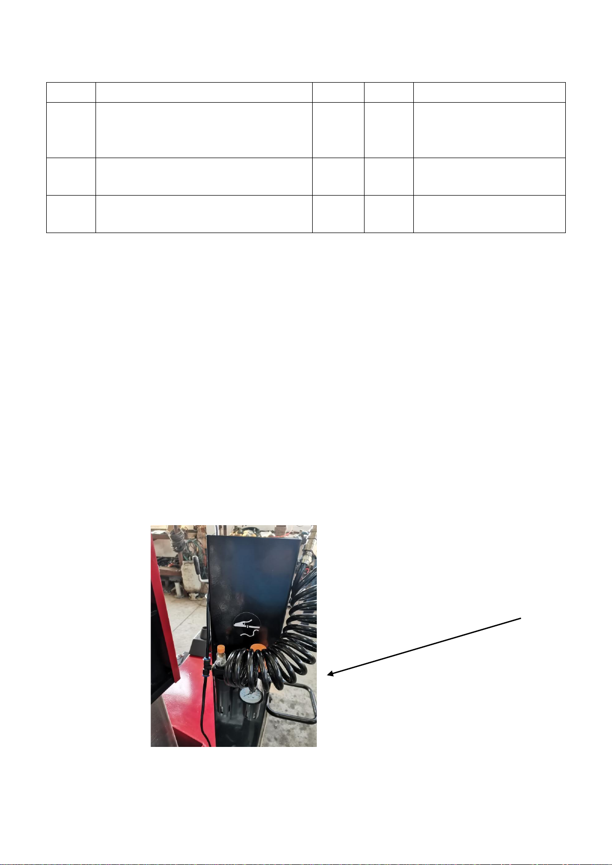
◇ As shown in Figure 7, the air supply is connected to machine by a pipe connector
(Q) on the side of Oil Drier.
Picture 7
Q

10
3.5.2 Debugging
Step 1: Pour some hydraulic oil into the Hydraulic Pump Box( The Hydraulic Oil should be
80% of the box). Turn on the Switch U, connect the power supply and watch the
turning position of the Pump. It will be OK if it is clockwise. If it is anticlockwise,
change the wires in the power supply. If the Power supply is 220V, just operate
directly. After 10-15 minutes the machine can be operated.
Step 2: Step the Motor Pedal (V) to try clockwise or anticlockwise.
Step 3: Check whether the Inflation gun whether supply air normally. Check whether the
Helper Arm (F) work normally as 7-A and 7-B. The pressure in the Oil Drier should be 6-8
(bar).
Step 4: Understand the hydraulic equipment movement to make the Hook forward and
backward as Picture7-E 7-F, Hook Wheel(Z) as Picture7-C 7-D and Hook Disk(K) as Picture
7-G 7-H.
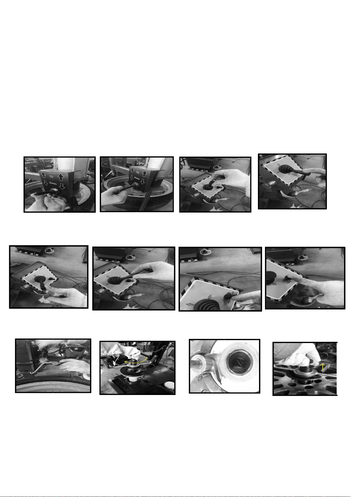
3.5.3 Hook head adjustment
◇ The position and angle of Hook Head has been adjusted standard by the manufacturer in
factory. The users should not change it. Upper of the Hook Head there is Hand
Wheel(which can be pulled upside). For the first time to use this machine, the users can
try changing the straight side and hook side with this Hand Wheel(as shown in
Picture 8).
◇ Try locking tires in Center Spindle and unlocking tires from Center Spindle. Turn plum
blossom top clockwise and move the lock part into the square slot, as shown in Picture
8-A and Picture 8-B, tires can be fixed in Center Spindle. Turn plum blossomtop counter-
clockwise and move the lock part out of the square slot, tires will get unlocked.Then pull
out the Lock Screw as shown in Picture 8-C.
11
Picture8
Picture8-A
Picture8-B
Picture8-C
Picture7-E
Picture7-F
Picture7-G
Picture7-G
Picture7-A
Picture7-C
Picture7-D
Picture7-B
12
Operation Declaration
4.1 Operating notes
◇ Ensure the connection to air supply, ensure there is no air leakage, and ensure the operation space can
meet the requirements before operation.
◇ Before any operation, the air in tires must be totally driven out, and the balance block of the tire balancing
device must be removed.
4.2 Demount and Mount Tires Operation Procedure
4.2.1
◇ Check whether the air inside of tires has been totally driven out. If not, please drive air out completely.
◇ As shown in Picture 9 and Picture 9-A, press tire with the wheel Disk and step the Motor Pedal to smear
the lubricating oil.
Picture 9 Picture 9-A
4.2.2 Demount tires◇ After bead breaking, the rim edge should be coated with
special lubricant. Fix tires in Center Spindle(Y) and lock it with Clamp Wheel (Note:
Make sure tires has locked tightly by Clamp Wheel). Shown as Picture 8-F, 8-G.
Picture 8-F Picture 8-G

13
4.2.4 Tire disassemble
◇ As shown in Picture 12, adjust the position to press Hook Head to wheels. Turn the twist on the right
Hand Control Valve and press the Hook Head into tires opposite the gaps between bead and rim.
◇ Turn the lower twist down to force a gap between the bead and the rim. Hook head is parallel to the rim
and 2mm against the rim. Then make it 2mm higher than rim. Insert the plastic crowbar between rim
and the top bead of the tire as shown in Picture 12-B(Protect Rims and Wheels). (Note: To run-flat tires,
the control twist(Z) must be turned backward and drive out the air in cylinder, or the Hood head may
rebound to scratch the wheels or even tear the bead. Please be especially careful to avoid the Hook Head
from touching the tire pressure monitoring device when demount tires with tire pressure monitoring
device.) Generally when Center Spindle turns a half circle the up bead can leave the wheel. Practice
more, it will never scratch or do other damage to wheels, rims or tires.
◇ As shown in Picture 12-D, pull the controller, make the Hook side down。
◇ As shown in Picture 12-D ,move the Hook Head (Z )against bottom rim about 3mm-5mm. Turn
up the twist(Z) with right hand and hold the lower bead of tire with left hand. The position of Hook
Head is as Picture12-E. Step motor pedal(V1), totally separate tires and wheels. (Notice: Hook Head
should be strictly fixed as the position shown in Picture12-E. Finishing disassembling tires, please turn
the Straight Side down and prepare mount tires. )
Notice:When demounting or mounting tires,Spindle should always turn clockwise;If Spindle
turn counterclockwise, it means the machine gets malfunction or the operator makes fault.
Picture 12 Picture 12-A
12B 12C

14
Picture 12-D Picture 12-E
Picture 12-F Picture 12-G
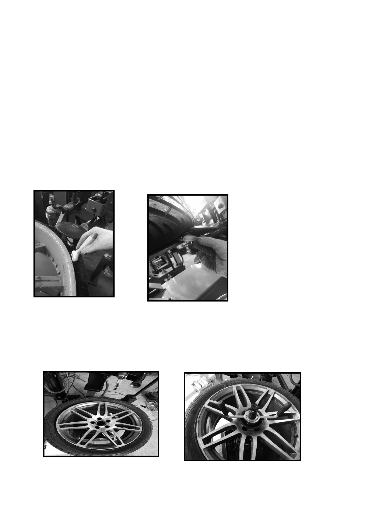
4.3.1 Mont Tires
◆After turn Straight Head downside,coat the lubricant up and down of rims as shown in
Picture 13-A and coat the lubricant to tires as shown in Picture 13-B.
◆Put the tire on the wheel as shown in Picture 13-B. The Straight Head should be about 4-
5mm to the rim and its Straight Head touches the tires as shown in Picture 13-B. Notice:
15
Pay attention to the distance of the Head. The distance to up rims of Hook Head should
be made according to the actual size of different tires. For tires with higher flat ratio, the
Hook Head should be a little higher. If it presses too deeply, the bottom bead of tires
cannot drop into the wheel. For the tires with lower flat ratio(soft tires) it can press
relatively more deeply. If it presses too shallow, the bottom bead of tires cannot drop into
the wheel either.
◆Press motor pedal and make the bottom bead of tires drop into wheel, finishing the lower
tire mount. Pull the Wheel Disk (K) against the rim about 2-4mm as shown in Picture 13-
D. Turn down the twist on Hand Control Valve(Z), forcing the Straight Head and Wheel
Disk to press the tire into the center of wheel 3-5mm. Press down on the left Hand Control
Valve, power the block of Left Helper Arm down to the rims 10-12mm as shown Picture
13-F. (Notice: For run-flat tires, please do always according to the actual condition adjust
the position of the Work Heading and the movement of hydraulic equipment. If the
Working Head is not adjusted in right position which stepping the Pedal, it will tear
tires.)Generally when the Center Spindle turns a circle tire can be mounted. Then turn
back the Hook Head, tire pressing roller and block as shown in Picture 13-G.
4.2.1 Inflation
Note:Inflation operation must be very carefully, strictly following the instructions for
inflation. If tires suddenly burst, the design and structure of tire changer is not able to protect
the operator's personal safety (or anything in the vicinity of the machine. In the process of
charging, as far as possible, make hands and the body be far away from tires). It is strongly
recommended to us professional inflatable tools (inflatable cage or other protective device
for the tire inflation).
Picture13-A
Picture13-B
Picture13-C
Picture13-D
Picture13-F
Picture13-G

16
◇ The burst of tires may cause severe damages to the operator or even death.
◇ Before getting inflated, check whether tires are damaged.
◇ Keep tires fixed in Center Spindle while getting inflated. If greater inflation pressure is
needed, professional protector cage for tire inflation is recommended for safety. Take the
following steps to use fixed inflation box to inflate.
①Connect the inflation nozzle to the tire valve(As shown in Picture 14).
②Confirm tire diameter is consistent with the diameter of its rim.
③ Step the Inflation Pedal and begin inflation. During this procedure control the pressure of
in Inflation Box until the tire fits to the rim
④Continue to inflate, and do always pay attention to Inflation Box pressure until the pressure
reaches the specified value of the tire. (Note: use the inflated gun to inflate the tire, regularly
check the pressure of the inflation gauge).
Picture 14
Maintenance, storage and scrap
5.1 Maintenance
5.1.1 Maintenance
◇ Prohibit unauthorized personnel for maintenance operation. To extend the service life of
the tire changer, maintenance should be performed according to the requirements of the
manual. If the machine is not maintained regularly, the operation and reliability can not
be guaranteed, and even cause danger to the operator or the people in the vicinity of the
machine. The manufacture will not be responsible for the accidents or results caused by
lack of regularly maintenance. Before any maintenance operation, circuit and gas supply
device must be disconnected ,turn off the switch. In order to release the pressure of the
air from the line, it is necessary to press the pedal 3-4 times.

17
◇ It must be professional staff to use the original spare parts do the timely replacement of
damaged parts. The safety device (safety valve, control valve) of the unauthorized
removal or replacement is a violation of state regulations on work safety. (Note: the
manufacturer is not responsible for damage caused by the parts of other manufacturer and
the damage caused by the disassembling of the safety device).
5.1.2 Tending 17
◇ Regular use of diesel oil to clean Center Spindle to prevent the formation of dirt. Coat
fixing clamps rail with lubricant oil.
◇ As shown in Picture 15-A, control oil mist level in the Oil Drier. If the oil level is lower,
you need to unscrew the Oil Drier cover F, and then as figure 15-A, add some oil.
When stepping the pedal 3 to 4 times, check whether there is oil drops into the oil cup F, if
not, adjust screw D.
◇ As shown in Picture 15-C, machine motor is not powerful enough, adjust the triangle belt
of the motor by the following steps: (before any operation, cut off the power)First,
Unscrew the 4 screws on the side of the box, remove the left side protective plate of the
tire changer. Second, use special adjustment screw X (Figure 15-C) that is in the motor
support base to adjust the triangle belt.
Picture 15-A Picture 15-B
Picture 15-C

18
5.2 Storage and scrap
5.2.1 Storage
◇ If long time storage of machine is needed, please disconnect all the energy supply, and
lubricate the skidway of the clamps on the Fixer to prevent oxidation.
5.2.2 Scrap
◇ In accordance with the law of the metal and nonmetal for scrap processing. In the
specified place release the oil inside the machine.
Common Fault causes and Solutions
Note: if you can notsolve the problem,please contact the manufacturer to providehelp.
We will be the first time to help you to solve the problem. Provide the relevant fault
information and fault pictures, thus the manufacturer can get rid of the trouble at the
fastest speed.
Problems
Causes
Resolutions
Unidirectional rotation of the
Center Spindle
Universal steering
switch damage
Replace universal
steering switch
Center Spindle does not rotate
Triangle damage
Replace triangle belt
Universal steering
switch damage
Replace universal
steering switch
Motor damage or wire
damage
Check motor and external plug
or socket.
The Clamp Wheel
cannot work
Dust or mist blocked the rail
Regularly coat lubricant
Hook Head loosens
Screws in Hook Head loosens
Tighten loosening screws
Pedals cannot rebound
Return spring has trouble
Replace return spring
Bead Breaking works hard
Silencer blockage
Clean or replace the silencer
Seals for Bead Breaker
cylinder damage
Replace damaged seals/Check
the Electricity wires.
Hydraulic works less
Valve or sealers damage
Change Valve or sealers

7.0 Explosive View
Table of contents
Popular Tyre Changer manuals by other brands

Mondolfo Ferro
Mondolfo Ferro As 944 LL Operator's manual

SICE
SICE S 100 PL instruction manual

Corghi
Corghi A 2030 Operator's manual

Hofmann Megaplan
Hofmann Megaplan Megamount 703 XL Installation, operation and maintenance guide - Original instructions

Hofmann
Hofmann monty 1620 Operation manual

M&B Engineering
M&B Engineering DIDO 30 Original instructions

Ranger Products
Ranger Products RX3040 Installation and operation manual

Launch
Launch TWC-581 INSTALLATION AND PARTS MANUAL

WilTec
WilTec 61309 Operation manual

Fasep
Fasep TOP AUTOMATIC 4.0 Operating and maintenance manual

Sealey
Sealey TC965 instructions

Base Line
Base Line 300 Safety Instructions, Set Up Instructions, Operation Instructions, Maintenance Instructions


