NI PXIe-7866 User manual

PXIe-7866
Getting Started
2023-03-31

Contents
Getting Started. . . . . . . . . . . . . . . . . . . . . . . . . . . . . . . . . . . . . . . . . . . . . . . . . . . . . . . . . . . . . . . . . 3
Unpacking the Kit. . . . . . . . . . . . . . . . . . . . . . . . . . . . . . . . . . . . . . . . . . . . . . . . . . . . . . . . . . . . 3
Verifying the Kit Contents. . . . . . . . . . . . . . . . . . . . . . . . . . . . . . . . . . . . . . . . . . . . . . . . . . . . . 4
Installing Soware on the Host Computer. . . . . . . . . . . . . . . . . . . . . . . . . . . . . . . . . . . . . . 4
Installing the NI PXIe-7866. . . . . . . . . . . . . . . . . . . . . . . . . . . . . . . . . . . . . . . . . . . . . . . . . . . . 5
Verifying Hardware Installation for Host Targets. . . . . . . . . . . . . . . . . . . . . . . . . . . . . . . . . 6
Verifying Hardware Installation for Remote Systems. . . . . . . . . . . . . . . . . . . . . . . . . . . . . 6
Connecting the NI PXIe-7866. . . . . . . . . . . . . . . . . . . . . . . . . . . . . . . . . . . . . . . . . . . . . . . . . . 7
Pinout. . . . . . . . . . . . . . . . . . . . . . . . . . . . . . . . . . . . . . . . . . . . . . . . . . . . . . . . . . . . . . . . . . . . . . 8
Where to Go Next. . . . . . . . . . . . . . . . . . . . . . . . . . . . . . . . . . . . . . . . . . . . . . . . . . . . . . . . . . . 10
NI Services. . . . . . . . . . . . . . . . . . . . . . . . . . . . . . . . . . . . . . . . . . . . . . . . . . . . . . . . . . . . . . . . . 10
ni.com
2
PXIe-7866 Getting Started

Getting Started
This document describes how to begin using the NI PXIe-7866.
© 2020–2021National Instruments Corporation. All rights reserved. Refer to the
<National Instruments>\_Legal Information directory for information about NI
copyright, patents, trademarks, warranties, product warnings, and export
compliance.
Unpacking the Kit
Notice To prevent electrostatic discharge (ESD) from damaging the
device, ground yourself using a grounding strap or by holding a grounded
object, such as your computer chassis.
1. Touch the antistatic package to a metal part of the computer chassis.
© National Instruments 3
PXIe-7866 Getting Started

2. Remove the device from the package and inspect the device for loose
components or any other sign of damage.
Notice Never touch the exposed pins of connectors.
Note Do not install a device if it appears damaged in any way.
3. Unpack any other items and documentation from the kit.
Store the device in the antistatic package when the device is not in use.
Verifying the Kit Contents
Verify that the following items are included in the NI PXIe-7866 kit.
Figure 1. NI PXIe-7866 Kit Contents
3
2
1
1. Hardware
2. NI-RIO Media
3. Getting Started Guide
Installing Soware on the Host Computer
Before using the NI PXIe-7866, you must install the following application soware
and device drivers on the host computer.
1. LabVIEW 2019 SP1 or later
2. LabVIEW Real-Time Module 2019 or later[1]
3. LabVIEW FPGA Module 2019 or later
4. NI R Series Multifunction RIO Device Drivers January 2020 or later
Visit ni.com/info and enter the Info Code sowareversion for minimum soware
support information.
ni.com
4
PXIe-7866 Getting Started

1 LabVIEW Real Time Module is only required when the R Series board is used in a
chassis where the PXIe Controller is running a real-time operating system.
Installing the NI PXIe-7866
Notice To prevent damage to the NI PXIe-7866 caused by ESD or
contamination, handle the module using the edges or the metal bracket.
1. Ensure the AC power source is connected to the chassis before installing the
module.
The AC power cord grounds the chassis and protects it from electrical damage
while you install the module.
2. Power o the chassis.
3. Inspect the slot pins on the chassis backplane for any bends or damage prior
to installation. Do not install a module if the backplane is damaged.
4. Remove the black plastic covers from all the captive screws on the module
front panel.
5. Identify a supported slot in the chassis. The following figure shows the
symbols that indicate the slot types.
Figure 2. Chassis Compatibility Symbols
12 3 45
1. PXI Express System Controller Slot
2. PXI Peripheral Slot
3. PXI Express Hybrid Peripheral Slot
4. PXI Express System Timing Slot
5. PXI Express Peripheral Slot
NI PXIe-7866 modules can be placed in PXIExpress peripheral slots,
PXIExpress hybrid peripheral slots, or PXI Express system timing slots.
6. Touch any metal part of the chassis to discharge static electricity.
© National Instruments 5
PXIe-7866 Getting Started

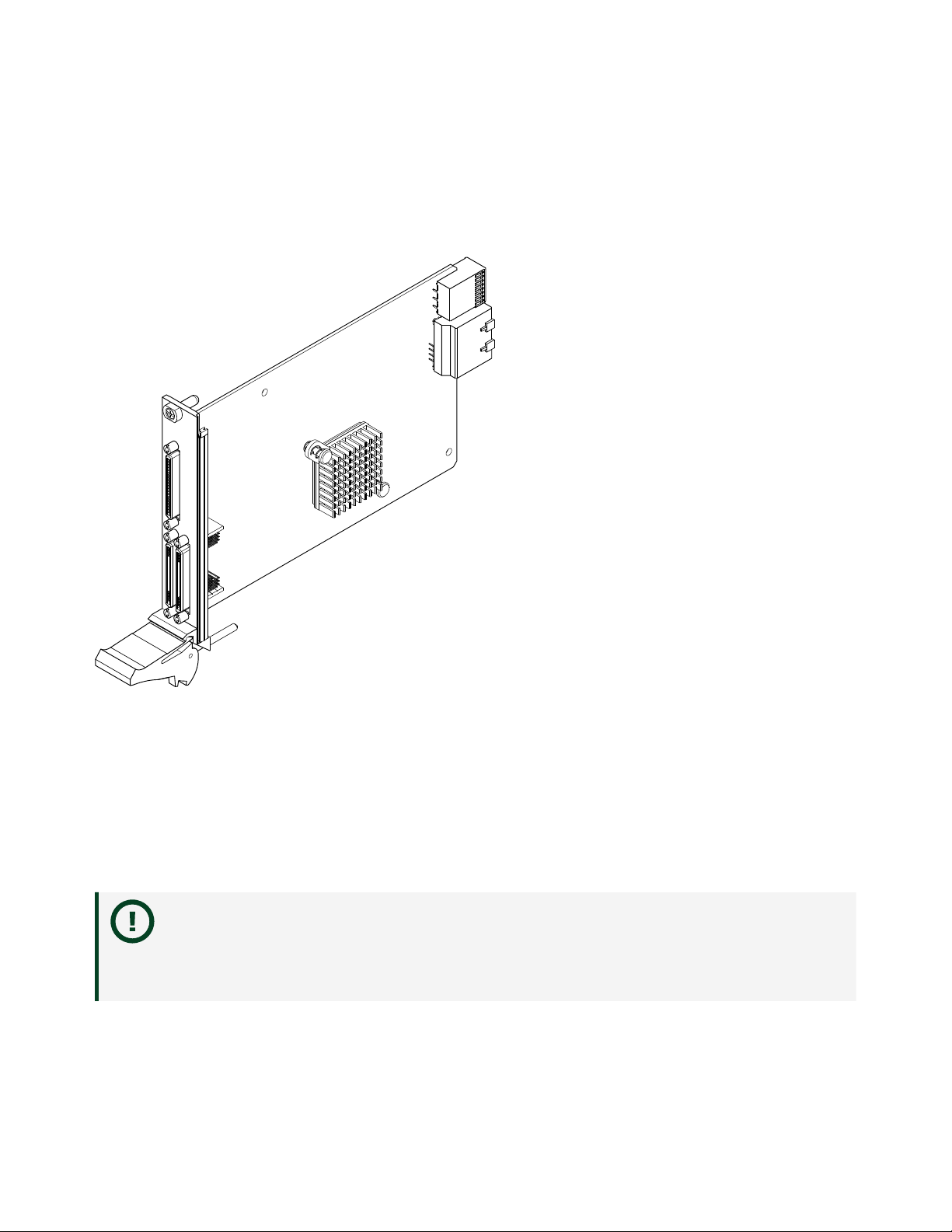
7. Place the module edges into the module guides at the top and bottom of the
chassis. Slide the module into the slot until it is fully inserted.
8. Secure the module front panel to the chassis using the front-panel mounting
screws.
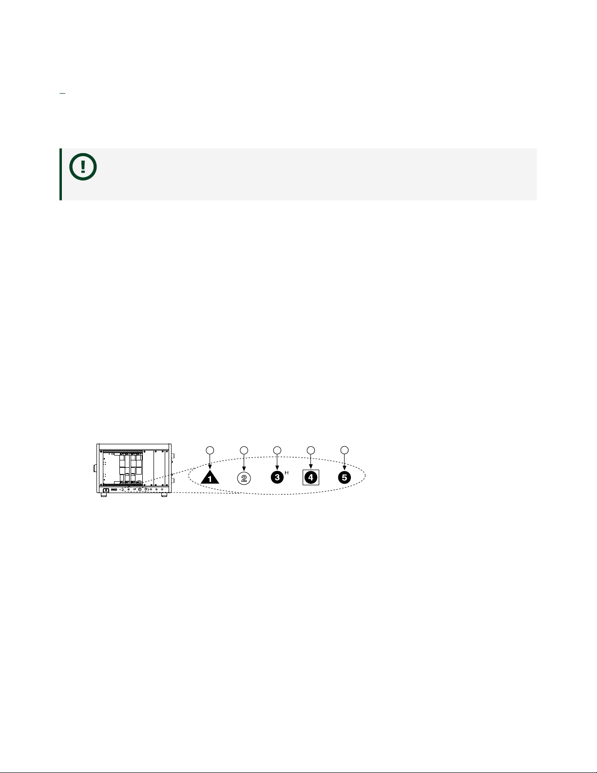
Note Tightening the top and bottom mounting screws increases
mechanical stability and also electrically connects the front panel to
the chassis, which can improve the signal quality and
electromagnetic performance.
9. Cover all empty slots using either filler panels (standard or EMC) or slot
blockers with filler panels, depending on your application.
Note For more information about installing slot blockers and filler
panels, go to ni.com/r/pxiblocker.
10. Power on the chassis.
Verifying Hardware Installation for Host Targets
You can verify that the system recognizes the NI PXIe-7866 by using Measurement &
Automation Explorer (MAX).
1. Launch MAX by navigating to Start » All Programs » National
Instruments » MAX or by clicking the MAX desktop icon.
2. Expand Devices and Interfaces.
3. Verify that the device appears under Devices and Interfaces.
If the device does not appear, press <F5> to refresh the view in MAX. If the
device does not appear aer refreshing the view, visit ni.com/support for
troubleshooting information.
Verifying Hardware Installation for Remote Systems
You can verify that the system recognizes the NI PXIe-7866 by using Measurement &
Automation Explorer (MAX).
1. Launch MAX on the host computer.
ni.com
6
PXIe-7866 Getting Started

2. Expand Remote Systems in the configuration tree and locate your system.
3. Install LabVIEW Real-Time Module2019 and NI R Series Multifunction RIO
Device Drivers January 2020 or later on your Remote System.
1. Refer to the Installing Soware on the Host Computer section for
information about installing soware on the host.
2. Refer to the PXI Express Controllers User Manual at ni.com/manuals
for information on installing soware on the target.
4. Under Remote Systems, find and expand Devices and Interfaces.
If the device does not appear, press <F5> to refresh the view in MAX. If the
device does not appear aer refreshing the view, visit ni.com/support for
troubleshooting information.
Connecting the NI PXIe-7866
NI recommends using the following cables and accessories with the NI PXIe-7866:
Table 1. Recommended Cables and Accessories
Connector Type Connector Block Cables
Analog I/O Connector 0 (RAIO) SCB-68A Noise Rejecting,
Shielded I/O Connector Block
(782536-01)
■SHC68-68-RMIO
Shielded Cable for the
Reconfigurable MIO
Connector, 68-pinD-Type
to 68-pin VHDCI,
1 m(189588-01)
■SHC68-68-RMIO
Shielded Cable for the
Reconfigurable MIO
Connector, 68-pinD-Type
to 68-pin VHDCI,
2 m(189588-02)
Analog Output Connector 2
(RAO)
Digital Connector 1 (RDIO) SCB-68 HSDIO Shielded 68-Pin
Connector Block for
Reconfigurable DIO & HSDIO
Products (782914-01)
■SHC68-C68-RDIO2
Shielded High Speed
Digital Cable for the
Reconfigurable DIO
Connector,
1 m(156166-01)
© National Instruments 7
PXIe-7866 Getting Started

Connector Type Connector Block Cables
■SHC68-C68-RDIO2
Shielded High Speed
Digital Cable for the
Reconfigurable DIO
Connector,
2 m(156166-02)
Note The SCB-68A DIP switches must be set for Direct Feedthrough mode
for use with R Series devices. Visit ni.com/info and enter the Info Code
scb68acables for more information on the SCB-68A accessory.
Note NI is not liable for connections that exceed any of the maximum
ratings of input or output signals on the NI PXIe-7866 and on the computer
chassis. Refer to the NI PXIe-7866 Specifications, available at ni.com/info
for the maximum input and output ratings for each signal.
Pinout
ni.com
8
PXIe-7866 Getting Started

NC
NC
NC
NC
NC
NC
NC
NC
NC
NC
NC
NC
NC
AO15
AO14
AO13
AO12
AO11
AO10
AO9
AO8
NC
AOCH23
NC
AOCH22
AOCH21
NC
AOCH20
AOCH19
NC
AOCH18
AOCH17
NC
AOCH16
NC
NC
NC
NC
NC
NC
NC
NC
NC
NC
NC
NC
NC
AOGND15
AOGND14
AOGND13
AOGND12
AOGND11
AOGND10
AOGND9
AOGND8
NC
AOGND23
NC
AOGND22
AOGND21
NC
AOGND20
AOGND19
NC
AOGND18
AOGND17
NC
AOGND16
68 34
67 33
66 32
65 31
64 30
63 29
62 28
61 27
60 26
59 25
58 24
57 23
56 22
55 21
54 20
53 19
52 18
51 17
50 16
49 15
48 14
47 13
46 12
45 11
44 10
43 9
42 8
41 7
40 6
39 5
38 4
37 3
36 2
35 1
CONNECTOR 2
(RAO)
TERMINAL 68
TERMINAL 34 TERMINAL 1
TERMINAL 35
+5V
NC
NC
NC
NC
NC
NC
NC
NC
NC
NC
NC
NC
AO7
AO6
AO5
AO4
AO3
AO2
AO1
AO0
AISENSE
NC
GND
NC
NC
GND
NC
NC
GND
NC
AI1+
AIGND0
AI0+
+5V
GND
GND
GND
GND
GND
GND
GND
GND
NC
NC
NC
NC
AOGND7
AOGND6
AOGND5
AOGND4
AOGND3
AOGND2
AOGND1
AOGND0
NC
NC
GND
NC
NC
GND
NC
NC
GND
NC
AI1–
AIGND1
AI0–
68 34
67 33
66 32
65 31
64 30
63 29
62 28
61 27
60 26
59 25
58 24
57 23
56 22
55 21
54 20
53 19
52 18
51 17
50 16
49 15
48 14
47 13
46 12
45 11
44 10
43 9
42 8
41 7
40 6
39 5
38 4
37 3
36 2
35 1
CONNECTOR 0
(RAIO)
TERMINAL 34 TERMINAL 1
TERMINAL 35
TERMINAL 68
DIO30
GND
DIO28
GND
DIO26
GND
DIO24
GND
DIO22
GND
DIO20
GND
DIO18
GND
DIO16
GND
DIO14
GND
DIO12
GND
DIO10
GND
DIO8
GND
DIO6
GND
DIO4
GND
DIO2
GND
DIO0
GND
EXTCLKIN
GND
DIO31
DIO29
GND
GND
DIO25
GND
DIO23
GND
DIO27
GND
DIO21
GND
DIO19
GND
DIO17
GND
DIO15
GND
DIO13
GND
DIO11
GND
DIO9
GND
DIO7
GND
DIO5
GND
DIO3
GND
DIO1
GND
GND
GND
68 34
67 33
66 32
65 31
64 30
63 29
62 28
61 27
60 26
59 25
58 24
57 23
56 22
55 21
54 20
53 19
52 18
51 17
50 16
49 15
48 14
47 13
46 12
45 11
44 10
43 9
42 8
41 7
40 6
39 5
38 4
37 3
36 2
35 1
CONNECTOR 1
(RDIO)
TERMINAL 68
TERMINAL 34 TERMINAL 1
TERMINAL 35
Table 2. NI PXIe-7866 Signal Descriptions
Signal Description
AI+ Positive analog input signal connection
AI- Negative analog input signal connection
AISENSE Reference connection for NRSE measurements
AIGND Ground reference for the analog input signal
AO Analog output signal connection
AOGND Ground reference for the analog output signal
DIO Digital input/output signal connection
EXTCLKIN External clock input source that can be used for
source synchronous acquisitions. The provided
clock source must be stable and glitch-free.
GND Ground connection
Supply (+5 Vout) 5 V power output connection for external
devices
© National Instruments 9
PXIe-7866 Getting Started

Signal Description
NC No connection
The NI PXIe-7866 is protected from overvoltage and overcurrent conditions.
Note Refer to the NI PXIe-7866 Specifications, available at ni.com/
manuals for more information.
Note The pinout label on the lid of the SCB-68A accessory is
incompatible with the NI PXIe-7866. Refer to the NI 78xxR Pinout Labels
for the SCB-68A, available at ni.com/manuals for the compatible pinout
labels.
Where to Go Next
SUPPORT
Services
ni.com/services
NI Community
ni.com/community
Software Support
ni.com/info>swsupport
Support
ni.com/support
SOFTWAREHARDWARE
NI PXIe-7866 Specifications
ni.com/manuals
PXI Express Controller Documentation
ni.com/manuals
PXI Express Chassis Documentation
ni.com/manuals
Configuring a Project
NI-RIO Help
Learn LabVIEW Basics
ni.com/gettingstarted
NI R Series Examples
NI Example Finder
NI PXIe-7866 User Manual
ni.com/manuals
NI PXIe-7866 Safety, Environment, and
Regulatory Information
ni.com/manuals
NI Services
ni.com
10
PXIe-7866 Getting Started

Visit ni.com/support to find support resources including documentation,
downloads, and troubleshooting and application development self-help such as
tutorials and examples.
Visit ni.com/services to learn about NI service oerings such as calibration options,
repair, and replacement.
Visit ni.com/register to register your NI product. Product registration facilitates
technical support and ensures that you receive important information updates from
NI.
NI corporate headquarters is located at 11500 N Mopac Expwy, Austin, TX,
78759-3504, USA.
© National Instruments 11
PXIe-7866 Getting Started
© 2023 National Instruments Corporation.
Table of contents
Other NI Computer Hardware manuals
Popular Computer Hardware manuals by other brands

Analog Devices
Analog Devices Blackfin Getting started

Advantech
Advantech ASMB-822I user manual

SIIG
SIIG DP FireWire 800 3-Port PCIe Quick installation guide

Lauterbach
Lauterbach C5000 Debugger manual

Sony
Sony HKPF-1125A Operation manual

ADLINK Technology
ADLINK Technology ROScube Pico BSP quick start guide

Arbor Technology
Arbor Technology ETX-PC/104+ Quick installation guide

Uctronics
Uctronics Raspberry Pi quick start guide

SeaLevel
SeaLevel Ultra-COMM+2/422.PCIe user manual

Sun Microsystems
Sun Microsystems XVR-1200 Installation and user guide

SOLIS
SOLIS DLS-W Connection guide

Supermicro
Supermicro Supero SAS-743TQ user guide