NI 5742 User manual
GETTING STARTED GUIDE
NI 5742
32-Channel Signal Generator
Note Before you begin, install and configure your chassis and controller.
The NI 5742 is a 32-channel, 1 MS/s analog output adapter module designed to work in
conjunction with your NI FlexRIO™ FPGA module.
The NI 5742 features 16-bit analog output channels that can be configured to drive either
unipolar or bipolar output.
This document explains how to install and connect signals for the NI 5742R, which is
composed of a FlexRIO FPGA module and the NI 5742.
Caution The protection provided by the NI 5742 can be impaired if it is used in a
manner not described in this document.
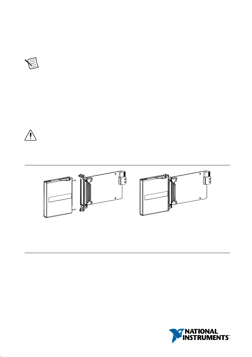
The following figure shows an example of a properly connected FlexRIO device.
Figure 1. FlexRIO Device
NI FlexRIO
Adapter Module + = NI FlexRIO Device
NI FlexRIO
FPGA Module
Contents
Installing the NI FlexRIO Adapter Module.............................................................................. 2
Electromagnetic Compatibility Guidelines...............................................................................3
How to Use Your FlexRIO Documentation.............................................................................. 4
FlexRIO Documentation Locations.................................................................................. 5
Verifying the System Requirements..........................................................................................6
Unpacking the Kit..................................................................................................................... 6
Preparing the Environment....................................................................................................... 7

Installing the Application Software and Driver........................................................................ 7
Installing the NI FlexRIO Devices............................................................................................8
Installing the NI FlexRIO Adapter Module...................................................................... 8
Connecting Cables.................................................................................................................... 9
Removing the Adapter Module...............................................................................................10
Disabling the Adapter Module in LabVIEW FPGA.......................................................10
Uninstalling the Module..................................................................................................10
Installing Accessories............................................................................................................. 10
Appendix A: NI 5742 Features............................................................................................... 11
Front Panel and Connector Pinouts.................................................................................11
Block Diagrams...............................................................................................................13
Appendix B: Interfacing with the NI 5742............................................................................. 14
Component-Level Intellectual Property (CLIP)............................................................. 14
Clocking.......................................................................................................................... 17
Where to Go Next................................................................................................................... 17
Worldwide Support and Services............................................................................................ 18
Installing the NI FlexRIO Adapter Module
Refer to the getting started guide for your FlexRIO FPGA module for FlexRIO FPGA module
installation instructions.
1. Gently insert the guide pins and the high-density card edge of the NI FlexRIO adapter
module into the corresponding connectors of the NI FlexRIO FPGA module, as shown in
the figure below.
2| ni.com | NI 5742 Getting Started Guide

Figure 2. Installing the NI FlexRIO Adapter Module
PXI-1000B
1
4
3
2
5
1. NI FlexRIO Adapter Module
2. Captive Screw
3. Guide Pin
4. PXI/PXI Express Chassis
5. NI FlexRIO FPGA Module
The connection may be tight, but do not force the adapter module into place.
2. Tighten the captive screws on the NI FlexRIO adapter module to secure it to the
NI FlexRIO FPGA module. NI recommends using the laser-tipped screwdriver (part
number 748677-01) included in the NI 5742 packaging.
3. Launch LabVIEW to begin configuring your NI FlexRIO system.
Electromagnetic Compatibility Guidelines
This product was tested and complies with the regulatory requirements and limits for
electromagnetic compatibility (EMC) stated in the product specifications. These requirements
and limits are designed to provide reasonable protection against harmful interference when the
product is operated in the intended operational electromagnetic environment.
This product is intended for use in industrial locations. However, harmful interference may
occur in some installations, when the product is connected to a peripheral device or test object,
or if the product is used in residential or commercial areas. To minimize interference with
radio and television reception and prevent unacceptable performance degradation, install and
use this product in strict accordance with the instructions in the product documentation.
Furthermore, any modifications to the product not expressly approved by National Instruments
could void your authority to operate it under your local regulatory rules.
NI 5742 Getting Started Guide | © National Instruments | 3
Caution To ensure the specified EMC performance, operate this product only with
shielded cables and accessories.
Note To ensure the specified EMC performance, the length of all I/O cables must
be no longer than 30 m (100 ft).
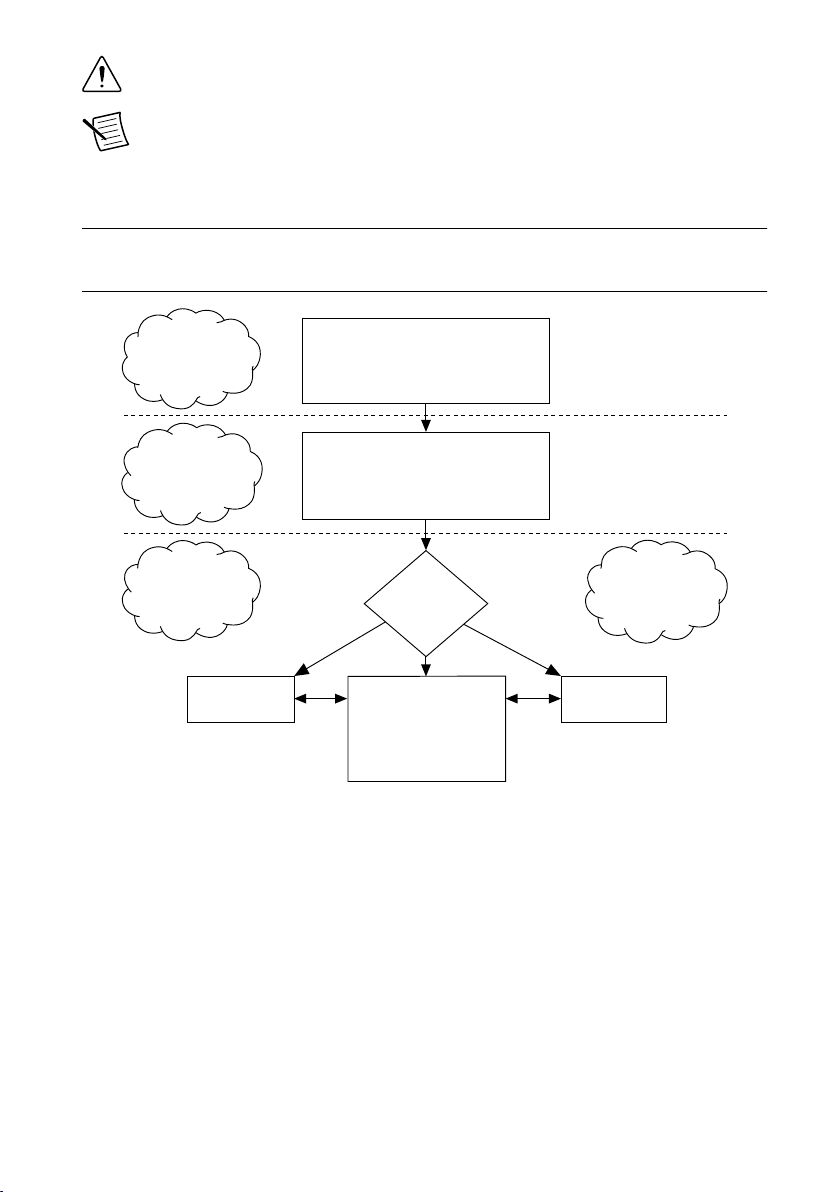
How to Use Your FlexRIO Documentation
Refer to the following flowchart for information about how to use FlexRIO documentation.
Figure 3. How to Use Your FlexRIO Documentation
LabVIEW FPGA
Module Help
NI FlexRIO
Help
LabVIEW
Examples
INSTALL Hardware
and Software
CONNECT Signals
and LearnAbout
Your AdapterModule
LEARN About
LabVIEW FPGA
Module
PROGRAM Your
NI FlexRIO System
in LabVIEW FPGA
Module
Specifications document
for your FPGA module
Specifications document
for your adapter module
Are
You New to
LabVIEW FPGA
Module?
Yes No
No
Getting Started Guide
for your adapter module
Getting Started Guide
for your FPGA module
NI FlexRIO Adapter
Module Development Kit
User Manual
4| ni.com | NI 5742 Getting Started Guide

FlexRIO Documentation Locations
Table 1. FlexRIO Documentation Locations and Descriptions
Document Location Description
Getting started guide
for your FPGA module
Available from the Start menu and
at ni.com/manuals.
Contains installation
instructions for your FlexRIO
system.
Specifications
document for your
FPGA module
Available from the Start menu and
at ni.com/manuals.
Contains specifications for
your FPGA module.
Getting started guide
for your adapter
module
Available from the Start menu and
at ni.com/manuals.
Contains signal information,
examples, and CLIP details for
your adapter module.
Specifications
document for your
adapter module
Available from the Start menu and
at ni.com/manuals.
Contains specifications for
your adapter module.
LabVIEW FPGA
Module Help
Embedded in LabVIEW Help and
at ni.com/manuals.
Contains information about
the basic functionality of the
LabVIEW FPGA Module.
NI FlexRIO Help Available from the Start menu and
at ni.com/manuals.
Contains information about
the FPGA module, adapter
module, and CLIP
configuration information.
NI FlexRIO Adapter
Module Development
Kit User Manual
Available from the Start menu at
Start»All Programs»National
Instruments»NI FlexRIO»NI
FlexRIO Adapter Module
Development Kit»
Documentation.
Contains information about
how to create custom adapter
modules for use with FlexRIO
FPGA modules.
LabVIEW Examples Available in NI Example Finder. In
LabVIEW, click Help»Find
Examples»Hardware Input and
Output»FlexRIO.
Contains examples of how to
run FPGA VIs and Host VIs
on your device.
NI 5742 Getting Started Guide | © National Instruments | 5

Table 1. FlexRIO Documentation Locations and Descriptions (Continued)
Document Location Description
IPNet Located at ni.com/ipnet. Contains LabVIEW FPGA
functions and intellectual
property to share.
NI FlexRIO product
page
Located at ni.com/flexrio. Contains product information
and data sheets for FlexRIO
devices.
Verifying the System Requirements
To use the NI 5742, your system must meet certain requirements. For more information about
minimum system requirements, recommended system, and supported application development
environments (ADEs), refer to the readme, which is available on the software media or online
at ni.com/updates.
Unpacking the Kit
Caution To prevent electrostatic discharge (ESD) from damaging the device,
ground yourself using a grounding strap or by holding a grounded object, such as
your computer chassis.
1. Touch the antistatic package to a metal part of the computer chassis.
2. Remove the device from the package and inspect the device for loose components or any
other sign of damage.
Caution Never touch the exposed pins of connectors.
Note Do not install a device if it appears damaged in any way.
3. Unpack any other items and documentation from the kit.
Store the device in the antistatic package when the device is not in use.
6| ni.com | NI 5742 Getting Started Guide

Preparing the Environment
Ensure that the environment you are using the NI 5742 in meets the following specifications.
............................................................................Operating temperature
(IEC 60068-2-1, IEC 60068-2-2)
0 °C to 55 °C
............................................................................Operating humidity
(IEC 60068-2-56)
10% to 90% RH, noncondensing
............................................................................Pollution Degree 2
............................................................................Maximum altitude 2,000 m at 25 °C ambient temperature
Indoor use only.
Note Refer to the NI 5742 Specifications at ni.com/manuals for complete
specifications.
Installing the Application Software and Driver
Before installing your hardware, you must install the application software and instrument
driver. Visit ni.com/info and enter rdsoftwareversion as the Info Code to determine
which minimum software versions you need for your device. Install the software in the
following order:
1. Install LabVIEW.
Refer to the LabVIEW Installation Guide for installation instructions for LabVIEW and
system requirements for the LabVIEW software. Refer to the LabVIEW Upgrade Notes
for additional information about upgrading to the most recent version of LabVIEW for
Windows. Documentation for LabVIEW is available at ni.com/manuals and by selecting
Start»All Programs»National Instruments»LabVIEW»LabVIEW Manuals.
2. Install the LabVIEW FPGA Module.
Refer to the LabVIEW FPGA Module Release and Upgrade Notes for installation
instructions and information about getting started with the LabVIEW FPGA Module.
Documentation for the LabVIEW FPGA Module is available at ni.com/manuals and by
selecting Start»All Programs»National Instruments»LabVIEW»LabVIEW
Manuals.
3. (Optional) Install the LabVIEW Real-Time Module.
Refer to the LabVIEW Real-Time Module Release and Upgrade Notes for system
requirements, installation instructions, and additional information about using the
LabVIEW Real-Time Module.
4. Install NI FlexRIO.
Refer to the NI FlexRIO Readme on the NI FlexRIO installation media for system
requirements and installation instructions for NI FlexRIO Support. Documentation for
NI 5742 Getting Started Guide | © National Instruments | 7
NI FlexRIO Support is available at ni.com/manuals and by selecting Start»All
Programs»National Instruments»NI FlexRIO.
Note If you are not using an adapter module, skip step 5.
5. Install NI FlexRIO Adapter Module Support.
Refer to the NI FlexRIO Adapter Module Support Readme on the NI FlexRIO Adapter
Module Support installation media for system requirements and installation instructions.
Documentation for NI FlexRIO Adapter Module Support is available at ni.com/manuals
and by selecting Start»All Programs»National Instruments»NI FlexRIO»NI FlexRIO
Adapter Module Documentation.
Installing the NI FlexRIO Devices
Note You must install the software before installing the hardware.
Installing the NI FlexRIO Adapter Module
Refer to the getting started guide for your FlexRIO FPGA module for FlexRIO FPGA module
installation instructions.
1. Gently insert the guide pins and the high-density card edge of the NI FlexRIO adapter
module into the corresponding connectors of the NI FlexRIO FPGA module, as shown in
the figure below.
8| ni.com | NI 5742 Getting Started Guide

Figure 4. Installing the NI FlexRIO Adapter Module
PXI-1000B
1
4
3
2
5
1. NI FlexRIO Adapter Module
2. Captive Screw
3. Guide Pin
4. PXI/PXI Express Chassis
5. NI FlexRIO FPGA Module
The connection may be tight, but do not force the adapter module into place.
2. Tighten the captive screws on the NI FlexRIO adapter module to secure it to the
NI FlexRIO FPGA module. NI recommends using the laser-tipped screwdriver (part
number 748677-01) included in the NI 5742 packaging.
3. Launch LabVIEW to begin configuring your NI FlexRIO system.
Connecting Cables
• Use any shielded50 Ω SMA cable to connect signals to the connectors on the front panel
of your NI 5742
• Use the SHH19-H19-AUX cable (NI part number: 152629-01 or 152629-02) to connect
to the digital I/O (DIO) and programmable function interface (PFI) signals on the AUX
I/O connector. NI recommends using the SCB-19 connector block to access the DIO and
PFI signals.
• Use the NI SHC68-C68-D4 VHDCI cable (NI part number: 196275-01) to connect to the
AO 0-31 connector.
NI 5742 Getting Started Guide | © National Instruments | 9

Removing the Adapter Module
Complete the following steps to remove the adapter module from the FlexRIO FPGA module.
Disabling the Adapter Module in LabVIEW FPGA
To properly remove an adapter module from the FlexRIO FPGA module, you must disable the
adapter module within the LabVIEW FPGA user interface. To disable the adapter module
within LabVIEW, complete the following steps.
1. In your LabVIEW Project Explorer window, right-click the IO Module item under the
FPGA Target and select Properties to display the IO Module Properties dialog box.
2. Click the Status category to view the adapter module Status dialog.
3. Deselect the checkbox for Enable IO Module Power. When this option is deselected,
firmware tristates the FlexRIO I/O and disables all adapter module power rails.
4. Click OK.
Uninstalling the Module
Caution If the module has been in use, it may exceed safe handling temperatures
and cause burns. Allow the module to cool before removing it from the chassis.
1. Disconnect any cables from the module front panel connectors.
Caution Disconnect any external clock or digital connections to the device
front panel. Applying external signals while the device is powered off may
cause damage.
2. Power off the chassis.
3. Ground yourself with a grounding strap or touch a grounded metal surface.
4. Unlatch the module by pushing down on the ejector handle.
5. Hold the module by the ejector handle and remove it from the slot.
Store the module in the original antistatic packaging when not in use to avoid damage.
Installing Accessories
The NI SMB-2153 is a breakout box accessory for debugging your NI 5742. The NI part
number for the NI SMB-2153 is 189408F-07L.
Related Information
For information about installing the NI SMB-2153, refer to the NI SMB-2153 Installation
Guide at ni.com/manuals.
10 | ni.com | NI 5742 Getting Started Guide
Table of contents
Other NI Control Unit manuals


Popular Control Unit manuals by other brands

Festo
Festo Compact Performance CP-FB6-E Brief description

Elo TouchSystems
Elo TouchSystems DMS-SA19P-EXTME Quick installation guide

JS Automation
JS Automation MPC3034A user manual

JAUDT
JAUDT SW GII 6406 Series Translation of the original operating instructions

Spektrum
Spektrum Air Module System manual

BOC Edwards
BOC Edwards Q Series instruction manual

KHADAS
KHADAS BT Magic quick start

Etherma
Etherma eNEXHO-IL Assembly and operating instructions

PMFoundations
PMFoundations Attenuverter Assembly guide

GEA
GEA VARIVENT Operating instruction

Walther Systemtechnik
Walther Systemtechnik VMS-05 Assembly instructions

Altronix
Altronix LINQ8PD Installation and programming manual


