manuals.online logo
Brands
  1. Home
  2. •
  3. Brands
  4. •
  5. Honeywell
  6. •
  7. Control Unit
  8. •
  9. Honeywell ADEMCO 4204 User manual

Honeywell ADEMCO 4204 User manual




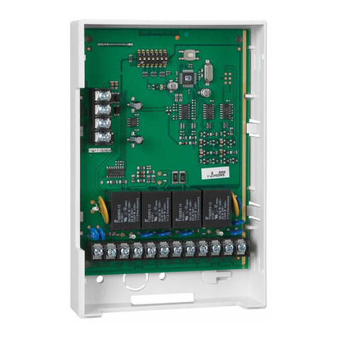
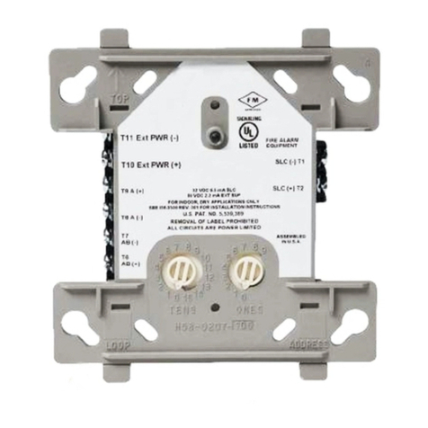
ADEMCO 4204 Relay Module – Installation Instructions
GENERAL INFORMATION
The ADEMCO 4204 Relay Module provides from one to
four dry, form-C (SPDT) relay outputs to compatible
control/communicators. It connects to the control’s
keypad wiring terminals.
The 4204 can be mounted inside the control’s cabinet
or mounted remotely depending on the application.
Refer to the UL notes below for certain restrictions.
If mounted remotely, the 4204 has a built-in tamper
switch that allows it to detect and report the removal of
its cover to the control. Second, communication to the
4204 is supervised so that it cannot be disconnected
from the keypad wiring without detection by the control.
If the wiring is cut, a tamper or alarm signal will result,
to indicate that this device (and possibly other devices
connected to the keypad wiring) has become
inoperative.
INSTALLATION
For UL Installations:
When used with controls that do not support cover
tamper or supervise communications wiring to the
4204, mount the 4204 inside the control’s cabinet.
When used with controls that support cover tamper and
supervise communications wiring to the 4204, mount
the 4204 may either be mounted inside the control’s
cabinet or mounted remotely.
When mounted inside the control’s cabinet, some
controls allow the 4204 to be mounted horizontally as
follows: insert the self-tapping screws (provided) in two
adjacent raised tabs on the back of the cabinet. Leave
the heads projecting 1/8”. Hang the 4204 on the screw
heads via two of the slotted holes on the back of its
housing. The 4204’s cover need not, in this case, be
tamper-protected. Set DIP switch 1 to “ON” if the cover
is not used (see table). See the control’s instructions
for additional information.
When the 4204 is mounted remotely, it can be mounted
horizontally or vertically and the built-in tamper switch
can be used. Wires can exit from the side or via the
breakout on the back of its housing. The DIP switch
must be set with its position 1 “OFF” and when the
installation is completed, the unit’s tamper-protected
cover must be replaced.
NOTE: For EN50131-3 compliance a tie-wrap must be
secured around the case of a remotely mounted 4204.
Apply tie-wrap around the case to the right of the large
zone wire opening (4-inch case width). This is in
opposition of the tamper switch and magnet.
NOTE: CE installations require maximum cable length
of 30 meters.
Affix the connections label that accompanies the 4204
to the inside of the 4204’s cover (if the cover is used) or
to the inside of the control’s cover.
CONNECTIONS AND SETTINGS
Select and set an address for the 4204, using its DIP
switch as shown in the DIP switch table. Each 4204
must be assigned a unique address so the control can
identify and communicate with the 4204. The address
to set is determined by the particular control to be used.
See the control’s installation instructions. As shipped,
the DIP switch is set for address “0”.









NOTE: 


Make connections to the 4204’s four relays via 12-
position terminal block TB2. Refer to the control’s
installation instructions for specific information on how
to program the activation options for the relays.

Make connections to the control’s keypad wiring points
via 4-position terminal block TB1, the 4-pin plug, or both
(wire color connections are the same). See the
diagram on the other side of this page.
SPECIFICATIONS
Physical: 6-7/16” W x 4-1/4” H x 1-1/4” D
(163mm x 108mm x 32mm)
Electrical:
Input Voltage: 12VDC nominal (10-14VDC, from
control’s remote keypad connection
points)
Input Current: 15mA standby + 40mA per active
relay
Contact Rating: 2A max. at 28VDC/AC (resistive
loads)
WARRANTY
For the latest warranty information, please go to:

UL

 !
"
#$ "
% 
 

&#
  
 '  
 ()*


N8909V4 10/12 Rev. B


4204-01-V1
4204 ADDRESS SETTINGS
("—" means "OFF")
DETERMINE 4204'S ADDRESS: CONTROL'S INSTRUCTIONS SPECIFY ADDRESS
TO USE. "0" ADDRESS SETTING SHOWN (AS SHIPPED).
SWITCH
NUMBER
0 1 2
3 4 5 6 78910 11 12 13 14 15
2
ON
—
ON —ON —ON —ON —ON —ON —ON —
3
ON ON
—
—ON ON ——ON ON ——ON ON ——
4
ON ON ON ON ————ON ON ON ON ————
5
ON ON ON ON ON ON ON ON —————— — —
1 2 3 4 5
Þ
DIP SWITCH SETTINGS
OFF ON
DIP SWITCH (WHITE AREAS DENOTE SWITCH HANDLES)
POSITIONS 2-6:
POSITION 1: ENABLES/DISABLES COVER TAMPER. ON = TAMPER DISABLED,
OFF = TAMPER ENABLED. SHOWN DISABLED AS SHIPPED.
6
ON ON ON ON ON ON ON ON
6 7
16 17 18 19 20 21 22 23 24 25 26 27 28 29 30 31
ON —ON —ON —ON —ON —ON —ON —ON —
ON ON ——ON ON
—
—ON ON ——ON ON ——
ON ON ON ON ——
—
—ON ON ON ON ————
ON ON ON ON ON ON ON ON —————— — —
—————— — —
——————
—
—
ON ON ON ON ON ON ON ON
POSITION 7: NO FUNCTION
TB2
121110
9
87654321
(–) GROUND
(+) 12VDC
YEL
BLK
GRN
RED
13 14 15 16
DIP SWITCH
FOR SETTING DEVICE ADDRESS
AND ENABLING/DISABLING TAMPER
COVER TAMPER (REED) SWITCH
TB1
4204
4-PIN TOUCHPAD PLUG
3
2
RELAY
1
4
TYPICAL
(SHOWN "OFF")
C
NC
NO
C
NC
NO
C
4204-02-V2
NC
NO
C
NC
NO
EITHER OR BOTH
CAN BE USED
DATA IN FROM CONTROL
DATA OUT TO CONTROL
RELAY
RELAY
RELAY
4204 CONNECTIONS
1 2 3 4 5 6 7
Must be connected to a
power-limited source.
If switching power
through a relay, the
power must be from a
power-limited source.
Relays are programmable
but outputs are not
supervised.
Supervised
REFER TO THE INSTALLATION INSTRUCTIONS FOR THE CONTROL WITH WHICH THIS DEVICE IS USED FOR
DETAILS REGARDING THE LIMITATIONS OFTHE ENTIRE ALARM SYSTEM.

+!+,#-../&#0&-/1#-..&11&-/100+.+/01

 !!"#$" 
%#

#11$!&&0!+2&#+100+.+/0
&''&''

((#(
%!')%
*+,&''-(%
.%(!%(
(

/ !(%
/ -%
/ $%%%%
/ $%%
/ *%%%
/ '01


&/!10,3#/!#11$100+.+/0
')'!'23445
'6)78$)445'


##4&#100+.+/0
%*+,&''-(-339+4!':;<+=%
(<9=%%(

'7+,>&''?-339+4!'30%<+=
'@6<9='6A66
6

9''B%(3+44
*:)0C4D4($%(8E++FDF
'

944G.!!



Other Honeywell Control Unit manuals

Honeywell SV2 Series User manual

Honeywell

Honeywell SV2 Series User manual

Honeywell SG150 User manual

Honeywell

Honeywell SG150 User manual

Honeywell 2MLL-PSRA User manual

Honeywell

Honeywell 2MLL-PSRA User manual

Honeywell Krom Schroder PFU 780 Manual

Honeywell

Honeywell Krom Schroder PFU 780 Manual

Honeywell D05FS-A Series User manual

Honeywell

Honeywell D05FS-A Series User manual

Honeywell GENT S4-34410 Instruction manual

Honeywell

Honeywell GENT S4-34410 Instruction manual

Honeywell CentraLine CLIOL822A Operation manual

Honeywell

Honeywell CentraLine CLIOL822A Operation manual

Honeywell C7110C1040 User manual

Honeywell

Honeywell C7110C1040 User manual

Honeywell Esser 8044 Series User manual

Honeywell

Honeywell Esser 8044 Series User manual

Honeywell D22 User manual

Honeywell

Honeywell D22 User manual

Honeywell SOMAT39 User manual

Honeywell

Honeywell SOMAT39 User manual

Honeywell V5825B User manual

Honeywell

Honeywell V5825B User manual

Honeywell MV300 User manual

Honeywell

Honeywell MV300 User manual

Honeywell Satronic DMG 973 User manual

Honeywell

Honeywell Satronic DMG 973 User manual

Honeywell TM3400 User manual

Honeywell

Honeywell TM3400 User manual

Honeywell NOTIFIER M700 Series User manual

Honeywell

Honeywell NOTIFIER M700 Series User manual

Honeywell VG.010A User manual

Honeywell

Honeywell VG.010A User manual

Honeywell PWT-BV Operation manual

Honeywell

Honeywell PWT-BV Operation manual

Honeywell Satronic TFI 812 Series User manual

Honeywell

Honeywell Satronic TFI 812 Series User manual

Honeywell UCIP-GPRS User manual

Honeywell

Honeywell UCIP-GPRS User manual

Honeywell BA295S User manual

Honeywell

Honeywell BA295S User manual

Honeywell Kromschroder BCM 400 B1 Series User manual

Honeywell

Honeywell Kromschroder BCM 400 B1 Series User manual

Honeywell DS05 User manual

Honeywell

Honeywell DS05 User manual

Honeywell Silent knight 5895XL Operating instructions

Honeywell

Honeywell Silent knight 5895XL Operating instructions

Popular Control Unit manuals by other brands

BiPVco Flextron installation manual

BiPVco

BiPVco Flextron installation manual

Cambricon MLU290-M5 product manual

Cambricon

Cambricon MLU290-M5 product manual

Lantronix PremierWave 2050 Command reference

Lantronix

Lantronix PremierWave 2050 Command reference

Enerpac VM2 instruction sheet

Enerpac

Enerpac VM2 instruction sheet

Jung 4074 TSM Product documentation

Jung

Jung 4074 TSM Product documentation

LEGRAND 4 149 29 Technical data sheet

LEGRAND

LEGRAND 4 149 29 Technical data sheet

Emerson Fisher 63EGLP Series instruction manual

Emerson

Emerson Fisher 63EGLP Series instruction manual

Harman AKG AMM 10 User instructions

Harman

Harman AKG AMM 10 User instructions

Ross RSe Series Integration guide

Ross

Ross RSe Series Integration guide

Texas Instruments TPS54232EVM-415 user guide

Texas Instruments

Texas Instruments TPS54232EVM-415 user guide

Danfoss KP 15 instructions

Danfoss

Danfoss KP 15 instructions

Cisco TelePresence Touch10 Guide

Cisco

Cisco TelePresence Touch10 Guide

VPro MAC Series instruction manual

VPro

VPro MAC Series instruction manual

Flo-Tite MPF155 Installation, operation and maintenance manual

Flo-Tite

Flo-Tite MPF155 Installation, operation and maintenance manual

Kaba Mauer 82132 Mounting instructions

Kaba Mauer

Kaba Mauer 82132 Mounting instructions

Ascon tecnologic exCOM installation manual

Ascon tecnologic

Ascon tecnologic exCOM installation manual

Hi-Par HP1000E Control user manual

Hi-Par

Hi-Par HP1000E Control user manual

ViscoTec preeflow plug n dose Operation & maintenance manual

ViscoTec

ViscoTec preeflow plug n dose Operation & maintenance manual

manuals.online logo
manuals.online logoBrands
  • About & Mission
  • Contact us
  • Privacy Policy
  • Terms and Conditions

Copyright 2025 Manuals.Online. All Rights Reserved.