NI NI-9237 User manual

NI-9237 Getting
Started
2022-07-06

Contents
Overview. . . . . . . . . . . . . . . . . . . . . . . . . . . . . . . . . . . . . . . . . . . . . . . . . . . . . . . . . . . . . . . . . . . . . . 3
Safety Guidelines. . . . . . . . . . . . . . . . . . . . . . . . . . . . . . . . . . . . . . . . . . . . . . . . . . . . . . . . . . . . 3
Safety Voltages. . . . . . . . . . . . . . . . . . . . . . . . . . . . . . . . . . . . . . . . . . . . . . . . . . . . . . . . . 3
Safety Guidelines for Hazardous Locations. . . . . . . . . . . . . . . . . . . . . . . . . . . . . . . . 4
Electromagnetic Compatibility Guidelines. . . . . . . . . . . . . . . . . . . . . . . . . . . . . . . . . . . . . . 5
Special Conditions for Marine Applications. . . . . . . . . . . . . . . . . . . . . . . . . . . . . . . . 6
Preparing the Environment. . . . . . . . . . . . . . . . . . . . . . . . . . . . . . . . . . . . . . . . . . . . . . . . . . . 6
Connecting the NI-9237. . . . . . . . . . . . . . . . . . . . . . . . . . . . . . . . . . . . . . . . . . . . . . . . . . . . . . 7
Signal Descriptions. . . . . . . . . . . . . . . . . . . . . . . . . . . . . . . . . . . . . . . . . . . . . . . . . . . . . 7
Connecting a Full Bridge. . . . . . . . . . . . . . . . . . . . . . . . . . . . . . . . . . . . . . . . . . . . . . . . . 8
Connecting a Half Bridge. . . . . . . . . . . . . . . . . . . . . . . . . . . . . . . . . . . . . . . . . . . . . . . . 8
Connecting a Quarter Bridge. . . . . . . . . . . . . . . . . . . . . . . . . . . . . . . . . . . . . . . . . . . . . 9
Connecting TEDS Sensors. . . . . . . . . . . . . . . . . . . . . . . . . . . . . . . . . . . . . . . . . . . . . . . 9
Where to Go Next. . . . . . . . . . . . . . . . . . . . . . . . . . . . . . . . . . . . . . . . . . . . . . . . . . . . . . . . . . . . 9
NI Services. . . . . . . . . . . . . . . . . . . . . . . . . . . . . . . . . . . . . . . . . . . . . . . . . . . . . . . . . . . . . . . . . 10
ni.com
2
NI-9237 Getting Started

Overview
This document explains how to connect to the NI-9237. In this document, the
NI-9237 with RJ-50 and the NI-9237 with DSUB are referred to inclusively as the
NI-9237.
Note Before you begin, read the NI-9237 Safety, Environmental, and
Regulatory Information document on ni.com/manuals and complete the
soware and hardware installation procedures in your chassis
documentation.
Note The guidelines in this document are specific to the NI-9237. The
other components in the system might not meet the same safety ratings.
Refer to the documentation for each component in the system to
determine the safety and EMC ratings for the entire system.
Safety Guidelines
Caution Observe all instructions and cautions in the user documentation.
Using the product in a manner not specified can damage the product and
compromise the built-in safety protection.
Attention Suivez toutes les instructions et respectez toutes les mises
en garde de la documentation d'utilisation. L'utilisation du produit de
toute autre façon que celle spécifiée risque de l'endommager et de
compromettre la protection de sécurité intégrée.
Safety Voltages
Connect only voltages that are within the following limits.
Between any two pins ±30 V maximum
© National Instruments 3
NI-9237 Getting Started
Isolation, channel-to-channel None
Isolation, channel-to-earth ground
Up to 3,000 m
Continuous 60 VDC, Measurement Category I
Withstand 1,000 Vrms, verified by a 5 s dielectric withstand test
Up to 5,000 m
Continuous 60 VDC, Measurement Category I
Withstand 860 Vrms, verified by a 5 s dielectric withstand test
Safety Guidelines for Hazardous Locations
The NI-9237 is suitable for use in Class I, Division 2, Groups A, B, C, D, T4 hazardous
locations; Class I, Zone 2, AEx nA IIC T4 Gc and Ex nA IIC T4 Gc hazardous locations;
and nonhazardous locations only. Follow these guidelines if you are installing the
NI-9237 in a potentially explosive environment. Not following these guidelines may
result in serious injury or death.
Caution Do not disconnect I/O-side wires or connectors unless power has
been switched o or the area is known to be nonhazardous.
Caution Do not remove modules unless power has been switched o or
the area is known to be nonhazardous.
Caution Substitution of components may impair suitability for Class I,
Division 2, or Zone 2.
Caution The system must be installed in an enclosure certified for the
intended hazardous (classified) location, having a tool secured cover/door,
where a minimum protection of at least IP54 is provided.
ni.com
4
NI-9237 Getting Started
Caution For Division 2 and Zone 2 applications, connected signals must
be within the following limits.
Capacitance 0.2 μF maximum
Inductance 80 mH maximum
Special Conditions for Hazardous Locations Use in Europe and
Internationally
The NI-9237 has been evaluated as Ex nA IIC T4 Gc equipment under
DEMKO 07ATEX 0626664X and is IECEx UL 14.0089X certified. Each NI-9237 is marked
II 3G and is suitable for use in Zone 2 hazardous locations, in ambient
temperatures of -40 °C ≤ Ta ≤ 70 °C. If you are using the NI-9237 in Gas Group IIC
hazardous locations, you must use the device in an NI chassis that has been
evaluated as Ex nC IIC T4, Ex IIC T4, Ex nA IIC T4, or Ex nL IIC T4 equipment.
Caution Transient protection shall be provided that is set at a level not
exceeding 140% of the peak rated voltage value of 85 V at the supply
terminals to the equipment.
Caution The system shall only be used in an area of not more than
Pollution Degree 2, as defined in IEC/EN 60664-1.
Caution The system shall be mounted in an ATEX/IECEx-certified
enclosure with a minimum ingress protection rating of at least IP54 as
defined in IEC/EN 60079-15.
Caution The enclosure must have a door or cover accessible only by the
use of a tool.
© National Instruments 5
NI-9237 Getting Started

Electromagnetic Compatibility Guidelines
This product was tested and complies with the regulatory requirements and limits
for electromagnetic compatibility (EMC) stated in the product specifications. These
requirements and limits provide reasonable protection against harmful interference
when the product is operated in the intended operational electromagnetic
environment.
This product is intended for use in industrial locations. However, harmful
interference may occur in some installations, when the product is connected to a
peripheral device or test object, or if the product is used in residential or
commercial areas. To minimize interference with radio and television reception and
prevent unacceptable performance degradation, install and use this product in strict
accordance with the instructions in the product documentation.
Furthermore, any changes or modifications to the product not expressly approved
by National Instruments could void your authority to operate it under your local
regulatory rules.
Special Conditions for Marine Applications
Some products are approved for marine (shipboard) applications. To verify marine
approval certification for a product, visit ni.com/product-certifications, search by
model number, and click the appropriate link.
Notice In order to meet the EMC requirements for marine applications,
install the product in a shielded enclosure with shielded and/or filtered
power and input/output ports. In addition, take precautions when
designing, selecting, and installing measurement probes and cables to
ensure that the desired EMC performance is attained.
Preparing the Environment
Ensure that the environment in which you are using the NI-9237 meets the following
specifications.
Operating temperature (IEC 60068-2-1, IEC 60068-2-2) -40 °C to 70 °C
ni.com
6
NI-9237 Getting Started
Operating humidity (IEC 60068-2-30) 10% RH to 90% RH, noncondensing
Pollution Degree 2
Maximum altitude 5,000 m
Indoor use only.
Note Refer to the NI-9237 Specifications on ni.com/manuals for
complete specifications.
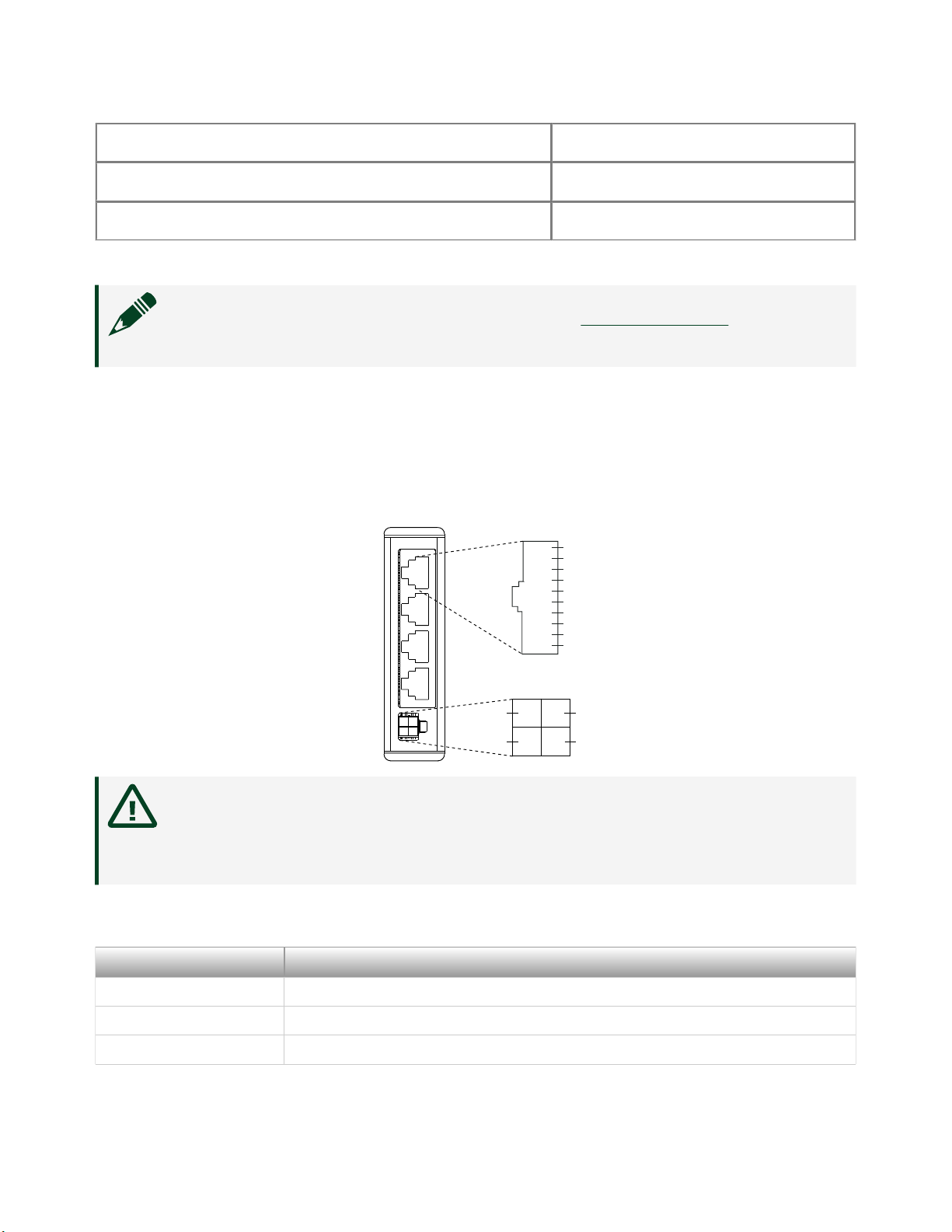
Connecting the NI-9237
The NI-9237 provides connections for four half or full bridges, and an external
excitation voltage source.
Figure 1. NI-9237 Pinout
SC
AI+
AI–
RS+
RS–
EX+
EX–
T+
T–
SC
1
2
3
4
5
6
7
8
9
10
Ch0 – Ch3
EX+ EX+
EX– EX–
Ch 0
Ch 1
Ch 2
Ch 3
Caution Do not use RJ-45 cables with the NI-9237 with RJ-50. RJ-45
cables damage the RJ-50 connector, permanently disabling the shunt
calibration, regardless of which connector you use.
Signal Descriptions
Signal Name Description
AI+ Positive analog input signal connection
AI- Negative analog input signal connection
RS+ Positive remote sensing connection
© National Instruments 7
NI-9237 Getting Started

Signal Name Description
RS- Negative remote sensing connection
EX+ Positive sensor excitation connection
EX- Negative sensor excitation connection
T+ TEDS data connection
T- TEDS return connection
SC Shunt calibration connection
Table 1. NI-9237 Signal Descriptions
Connecting a Full Bridge
You can connect a full bridge to the NI-9237.
Figure 2. Connecting a Full Bridge to the NI-9237
You also can connect floating signals to the NI-9237. If you connect floating signals
to the NI-9237, NI recommends connecting the EX- signal to the earth ground or
shield for better noise rejection.
Connecting a Half Bridge
You can connect a half bridge to the NI-9237.
Figure 3. Connecting a Half Bridge to the NI-9237
You also can connect floating signals to the NI-9237. If you connect floating signals
to the NI-9237, NI recommends connecting the EX- signal to the earth ground or
shield for better noise rejection.
ni.com
8
NI-9237 Getting Started

Bridge Calibration
When you insert or remove a new sensor from the NI-9237, slight changes in the
excitation voltages can cause a mismatch between the internal half-bridge
completion resistors and the half-bridge sensors, which results in a change in the
measurement osets. NI recommends performing bridge calibrations of quarter- or
half-bridge sensors aer connecting all sensors to the NI-9237 and aer removing or
attaching any additional sensor. For more information about changes in voltage
osets in the NI-9237, visit ni.com/info and enter the Info Code rdw9237.
Connecting a Quarter Bridge
You can connect a quarter bridge to the NI-9237 by adding a resistor externally to
create a half bridge.
Figure 4. Connecting a Quarter Bridge to the NI-9237
You also can use a quarter bridge with the NI-9237 with RJ-50 if you use the NI 9944
or NI 9945 Quarter Bridge Completion Accessory.
Connecting TEDS Sensors
You can connect TEDs sensors to the NI-9237.
Figure 5. Connecting TEDS Sensors to the NI-9237
Ensure that neither the TEDS data (T+) nor the TEDS return (T-) signal is tied in
common to any AI signals on the NI-9237. The NI-9237 connects all the T- signals
together internally. The NI-9237 with DSUB has only three T- pins. To connect four
TEDS sensors to the NI-9237 with DSUB, wire the TEDS return signals of two of the
sensors to one of the T- pins.
© National Instruments 9
NI-9237 Getting Started

Where to Go Next
NI Services
Visit ni.com/support to find support resources including documentation,
downloads, and troubleshooting and application development self-help such as
tutorials and examples.
Visit ni.com/services to learn about NI service oerings such as calibration options,
repair, and replacement.
Visit ni.com/register to register your NI product. Product registration facilitates
technical support and ensures that you receive important information updates from
NI.
NI corporate headquarters is located at 11500 N Mopac Expwy, Austin, TX,
78759-3504, USA.
ni.com
10
NI-9237 Getting Started
© 2022 National Instruments Corporation.
Table of contents
Other NI Control Unit manuals


Popular Control Unit manuals by other brands

Festo
Festo Compact Performance CP-FB6-E Brief description

Elo TouchSystems
Elo TouchSystems DMS-SA19P-EXTME Quick installation guide

JS Automation
JS Automation MPC3034A user manual

JAUDT
JAUDT SW GII 6406 Series Translation of the original operating instructions

Spektrum
Spektrum Air Module System manual

BOC Edwards
BOC Edwards Q Series instruction manual

KHADAS
KHADAS BT Magic quick start

Etherma
Etherma eNEXHO-IL Assembly and operating instructions

PMFoundations
PMFoundations Attenuverter Assembly guide

GEA
GEA VARIVENT Operating instruction

Walther Systemtechnik
Walther Systemtechnik VMS-05 Assembly instructions

Altronix
Altronix LINQ8PD Installation and programming manual


