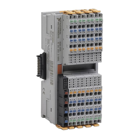
NI 9201E User manual

OPERATING INSTRUCTIONS AND SPECIFICATIONS
NI 9201E/9221E
8-Channel, 12-Bit Analog Input Modules

NI 9201E/9221E 2 ni.com
This document describes how to use the National Instruments 9201E
and National Instruments 9221E and includes dimensions, terminal
assignments, and specifications for the NI 9201E/9221E. In this
document, the NI 9201E/9221E with screw terminal
and NI 9201E/9221E with DSUB are referred to inclusively
as the NI 9201E/9221E. Visit ni.com/info and enter
rdsoftwareversion to determine which software you need for the
modules you are using. For information about installing, configuring,
and programming the system, refer to the system documentation. Visit
ni.com/info and enter cseriesdoc for information about
C Series documentation.
Caution National Instruments makes no electromagnetic
compatibility (EMC) or CE marking compliance claims
for the NI 9201E/9221E. The end-product supplier is
responsible for conformity to any and all compliance
requirements.
Caution The NI 9201E/9221E must be installed inside a
suitable enclosure prior to use. Hazardous voltages may
be present.

© National Instruments Corp. 3 NI 9201E/9221E
NI 9201E/9221E Dimensions
The following figure shows the dimensions of the
NI 9201E/9221E.
Figure 1. NI 9201E/9221E Dimensions in Millimeters (Inches)
73.4 (2.89)
0.0 (0.00)
26.7 (1.05)
58.4 (2.30)
66.0 (2.60)
0.0 (0.00)

NI 9201E/9221E 4 ni.com
Connecting the NI 9201E/9221E
The NI 9201E/9221E provides connections for eight analog input
channels.
Figure 2. NI 9201E/9221E Terminal and Pin Assignments
COM
NC
COM
COM
NC
COM
COM
NC
COM
COM
NC
COM
COM
AI0
NC
AI1
AI2
NC
AI3
AI4
NC
AI5
AI6
NC
AI7
1
2
3
4
5
6
7
8
9
10
11
12
13
14
15
16
17
18
19
20
21
22
23
24
25
AI0
AI1
AI2
AI3
AI4
AI5
AI6
AI7
NC
COM
0
1
2
3
4
5
6
7
8
9

© National Instruments Corp. 5 NI 9201E/9221E
The NI 9201E/9221E with screw terminal has a 10-terminal,
detachable screw-terminal connector. The NI 9201E/9221E with
DSUB has a 25-pin DSUB connector. Each channel has an AI
terminal or pin to which you can connect a voltage signal. COM,
the common terminal or pin, is internally connected to the isolated
ground reference of the module.
The NI 9201E/9221E channels are isolated from other modules in
the system. The module protects each channel from overvoltages.
Refer to the Specifications section for more information about
overvoltage protection. The input signals are scanned, buffered,
conditioned, and then sampled by a single 12-bit ADC. Refer to
Figure 3 for an illustration of the input circuitry on the
NI 9201E/9221E.
Figure 3. Input Circuitry on the NI 9201E/9221E
NI 9201E/9221E
Buffer Isolated
ADC
Overvoltage
Protection Mux
COM
AI7
AI0

NI 9201E/9221E 6 ni.com
You can connect single-ended voltage signals to the
NI 9201E/9221E. Connect the positive lead of the voltage signal
to AI. Connect the ground signal to COM. Refer to Figure 4 for an
illustration of connecting a single-ended voltage signal to the
NI 9201E/9221E.
Figure 4. Connecting a Single-Ended Voltage Signal to the NI 9201E/9221E
Note You must use 2-wire ferrules to create a secure
connection when connecting more than one wire to a
single terminal on the NI 9201E/9221E with screw
terminal.
COM
AI
+
–
Voltage
Source
NI 9201E/9221E

© National Instruments Corp. 7 NI 9201E/9221E
Sleep Mode
This module supports a low-power sleep mode. Support for sleep
mode at the system level depends on the chassis that the module is
plugged into. Refer to the chassis manual for information about
support for sleep mode. If the chassis supports sleep mode, refer to
the software help for information about enabling sleep mode. Visit
ni.com/info and enter cseriesdoc for information about
C Series documentation.
Typically, when a system is in sleep mode, you cannot
communicate with the modules. In sleep mode, the system
consumes minimal power and may dissipate less heat than it does
in normal mode. Refer to the Specifications section for more
information about power consumption and thermal dissipation.

NI 9201E/9221E 8 ni.com
Specifications
The following specifications are typical for the range –40 to 85 °C
internal to any enclosures unless otherwise noted. All voltages are
relative to COM unless otherwise noted. The specifications are the
same for the NI 9201E and the NI 9221E unless otherwise noted.
Input Characteristics
Number of channels..........................8 analog input channels
ADC resolution................................. 12 bits
Type of ADC..................................... Successive approximation
register (SAR)
Sample rate (aggregate)
Module
Maximum
Sample Rate
(R Series Expansion Chassis)
Maximum
Sample Rate
(All Other Chassis)
NI 9201E,
single channel
475 kS/s 800 kS/s
NI 9201E,
scanning
475 kS/s 500 kS/s
NI 9221E 475 kS/s 800 kS/s

© National Instruments Corp. 9 NI 9201E/9221E
Input range
NI 9201E ....................................±10 V
NI 9221E ....................................±60 V
Operating voltage ranges
Overvoltage protection
(channel-to-COM) ............................ ±100 V
Module
Measurement Voltage,
Channel-to-COM
Maximum Voltage,
Channel-to-Earth Ground
or COM-to-Earth Ground
Min
(V)
Typ
(V)
Max
(V)
Screw
Ter mi nal DSUB
NI 9201E ±10.3 ±10.53 ±10.8 250 Vrms ±60 VDC
NI 9221E ±61.4 ±62.50 ±63.8

NI 9201E/9221E 10 ni.com
NI 9201E accuracy (excludes noise)
Measurement Conditions
Percent of
Reading
(Gain Error)
Percent of
Range*
(Offset Error)
Calibrated typ (25 °C, ±5 °C) ±0.04% ±0.07%
Calibrated max (–40 to 85 °C) ±0.25% ±0.25%
Uncalibrated typ (25 °C, ±5 °C) ±0.26% ±0.46%
Uncalibrated max (–40 to 85 °C) ±0.67% ±1.25%
*Range equals 10.53 V

© National Instruments Corp. 11 NI 9201E/9221E
NI 9221E accuracy (excludes noise)
Stability
Gain drift ....................................±34 ppm/°C
Offset drift
NI 9201E.............................. ±100 V/°C
NI 9221E.............................. ±580 V/°C
Input bandwidth (–3 dB)
NI 9201E ....................................690 kHz min
NI 9221E ....................................950 kHz min
Measurement Conditions
Percent of
Reading
(Gain Error)
Percent of
Range*
(Offset Error)
Calibrated typ (25 °C, ±5 °C) ±0.04% ±0.07%
Calibrated max (–40 to 85 °C) ±0.25% ±0.25%
Uncalibrated typ (25 °C, ±5 °C) ±0.26% ±0.43%
Uncalibrated max (–40 to 85 °C) ±0.67% ±1.06%
*Range equals 62.50 V

NI 9201E/9221E 12 ni.com
Input impedance
Resistance................................... 1 M
Capacitance ................................ 5 pF
Input noise (code-centered)
RMS ...........................................0.7 LSBrms
Peak-to-peak............................... 5 LSB
No missing codes.............................. 12 bits
DNL .................................................. –0.9 to 1.5 LSB
INL.................................................... ±1.5 LSB
Crosstalk (at 10 kHz)........................–75 dB
Settling time (to 1 LSB)
NI 9201E ....................................2 s
NI 9221E ....................................1.25 s
MTBF ...............................................1,092,512 hours at 25 °C;
Bellcore Issue 2, Method 1,
Case 3, Limited Part Stress
Method

© National Instruments Corp. 13 NI 9201E/9221E
Note Contact NI for Bellcore MTBF specifications
at other temperatures or for MIL-HDBK-217F
specifications.
Power Requirements
Power consumption from chassis
Active mode ............................... 1 W max
Sleep mode ................................. 1 mW max
Thermal dissipation (at 85 °C)
Active mode ............................... 1 mW max
Sleep mode ................................. 32 mW max
Physical Characteristics
Use a dry, low-velocity stream of air to clean the module. If
needed, use a soft-bristle brush for cleaning around components.
Note For two-dimensional drawings and
three-dimensional models of the C Series module and
connectors, visit ni.com/dimensions and search by
module number.

NI 9201E/9221E 14 ni.com
Screw-terminal wiring ...................... 12 to 24 AWG copper
conductor wire with 10 mm
(0.39 in.) of insulation
stripped from the end
Torque for screw terminals ............... 0.5 to 0.6 N · m
(4.4 to 5.3 lb · in.)
Ferrules ............................................. 0.25 mm2to 2.5 mm2
Weight
NI 9201E/9221E
with screw terminal .................... 64 g (2.2 oz)
NI 9201E/9221E with DSUB..... 44 g (1.6 oz)
Safety
Safety Voltages
Connect only voltages that are within the following limits.
Channel-to-COM 60 VDC max

© National Instruments Corp. 15 NI 9201E/9221E
NI 9201E/9221E with Screw Terminal Isolation Voltages
Channel-to-channel........................... None
Channel-to-earth ground
Continuous ................................. 250 Vrms,
Measurement Category II,
(Double insulation)
Withstand....................................2,300 Vrms, verified by a 5 s
dielectric withstand test
Measurement Category II is for measurements performed on
circuits directly connected to the electrical distribution system.
This category refers to local-level electrical distribution, such as
that provided by a standard wall outlet, for example, 115 V for U.S.
or 230 V for Europe.
Caution Do not connect the NI 9201E/9221E with screw
terminal to signals or use for measurements within
Measurement Categories III or IV.

NI 9201E/9221E 16 ni.com
NI 9201E/9221E with DSUB Isolation Voltages
Channel-to-channel........................... None
Channel-to-earth ground
Continuous ................................. 60 VDC,
Measurement Category I,
(Double insulation)
Withstand....................................1,000 Vrms, verified by a 5 s
dielectric withstand test
Measurement Category I is for measurements performed on
circuits not directly connected to the electrical distribution system
referred to as MAINS voltage. MAINS is a hazardous live electrical
supply system that powers equipment. This category is for
measurements of voltages from specially protected secondary
circuits. Such voltage measurements include signal levels, special
equipment, limited-energy parts of equipment, circuits powered by
regulated low-voltage sources, and electronics.
Caution Do not connect the NI 9201E/9221E with DSUB
to signals or use for measurements within Measurement
Categories II, III, or IV.

© National Instruments Corp. 17 NI 9201E/9221E
Safety Standards
This product meets the requirements of the following standards of
safety for electrical equipment for measurement, control, and
laboratory use when installed in a suitable enclosure:
• IEC 61010-1, EN 61010-1
• UL 61010-1, CSA 61010-1
Note For UL and other safety certifications, refer to the
product label or the Online Product Certification section.
Online Product Certification
Refer to the product Declaration of Conformity (DoC) for
additional regulatory compliance information. To obtain product
certifications and the DoC for this product, visit ni.com/
certification, search by module number or product line, and
click the appropriate link in the Certification column.

NI 9201E/9221E 18 ni.com
Environmental
National Instruments C Series modules are intended for indoor use
only but may be used outdoors if installed in a suitable enclosure.
Refer to the manual for the chassis you are using for more
information about meeting these specifications.
Operating temperature
(IEC 60068-2-1, IEC 60068-2-2) ..... –40 to 85 °C
Storage temperature
(IEC 60068-2-1, IEC 60068-2-2) ..... –40 to 85 °C
Operating humidity
(IEC 60068-2-56)..............................10 to 90% RH,
noncondensing
Storage humidity
(IEC 60068-2-56)..............................5 to 95% RH,
noncondensing
Maximum altitude.............................2,000 m
Pollution Degree ............................... 2

© National Instruments Corp. 19 NI 9201E/9221E
Environmental Management
National Instruments is committed to designing and manufacturing
products in an environmentally responsible manner. NI recognizes
that eliminating certain hazardous substances from our products is
beneficial to the environment and to NI customers.
For additional environmental information, refer to the NI and the
Environment Web page at ni.com/environment. This page
contains the environmental regulations and directives with which
NI complies, as well as other environmental information not
included in this document.
Waste Electrical and Electronic Equipment (WEEE)
EU Customers At the end of the life cycle, all products
must be sent to a WEEE recycling center. For more
information about WEEE recycling centers and National
Instruments WEEE initiatives, visit ni.com/
environment/weee.

NI 9201E/9221E 20 ni.com
Calibration
You can obtain the calibration certificate and information about
calibration services for the NI 9201E/9221E at ni.com/
calibration.
Calibration interval ........................... 1 year
⬉ᄤֵᙃѻક∵ᶧࠊㅵ⧚ࡲ⊩ ˄Ё RoHS˅
Ёᅶ᠋ National Instruments ヺড়Ё⬉ᄤֵᙃ
ѻકЁ䰤ࠊՓ⫼ᶤѯ᳝ᆇ⠽䋼ᣛҸ (RoHS)DŽ݇Ѣ
National Instruments Ё RoHS ড়㾘ᗻֵᙃˈ䇋ⱏᔩ
ni.com/environment/rohs_chinaDŽ(For information
about China RoHS compliance, go to ni.com/
environment/rohs_china.)
This manual suits for next models
1
Table of contents
Other NI Control Unit manuals