NI GPIB Series Installation instructions

TitleShort-Hidden -1 ©National Instruments Corporation
1
GPIB Hardware Guide
CONFIGURATION AND INSTALLATION
AT-GPIB-TNT
GPIB-PCII/IIA
PC/104-GPIB
NEC-GPIB/TNT
INSTALLATION
AT-GPIB/TNT (PnP) and AT-GPIB/TNT+
GPIB-1394
GPIB-USB-A
NEC-GPIB/TNT (PnP)
PCI-GPIB and PCI-GPIB+
PCMCIA-GPIB and PCMCIA-GPIB+
PMC-GPIB
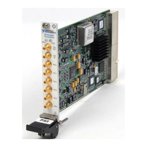
PXI-GPIB
SPECIFICATIONS
TECHNICAL SUPPORT
IMPORTANT INFORMATION
COMPLIANCE
322296B-01, March 2000

HOME
TitleShort-Hidden -2
©
National Instruments Corporation
Configure and Install Your AT-GPIB/TNT Next
Step
2
Configure and Install Your AT-GPIB/TNT
1. Configure the AT-GPIB/TNT Base I/O Address
2. Configure the AT-GPIB/TNT Interrupt Line (IRQ).
3. Configure the AT-GPIB/TNT DMA Channel.
After you finish these steps, you are ready to Install the AT-GPIB/TNT.

HOME
TitleShort-Hidden -4
©
National Instruments Corporation
Configure and Install Your AT-GPIB/TNT Next
Step
Previous
Step
4
Configure the AT-GPIB/TNT Base I/O Address
Click on the base I/O address assigned to your AT-GPIB/TNT from the list below, and change the
switch settings to match the base I/O address assigned to your board.
If you do not know what resources were assigned to your AT-GPIB/TNT, click here to Determine
Assigned Resources.
100 200 300
120 220 320
140 240 340
160 260 360
180 280 380
1A0 2A0 3A0
1C0 2C0*3C0
1E0 2E0 3E0
* default setting

HOME
TitleShort-Hidden -5
©
National Instruments Corporation
Configure and Install Your AT-GPIB/TNT Next
Step
Previous
Step
5
Table 1. Possible Base I/O Address Switch Settings for AT-GPIB/TNT
Base I/O
Address (hex) Switch Setting
Base I/O
Address (hex) Switch Setting
100 120
140 160
180 1A0
1C0 1E0
A9
OFF
A8
A7
A6
A5
A9
OFF
A8
A7
A6
A5
A9
OFF
A8
A7
A6
A5
A9
OFF
A8
A7
A6
A5
A9
OFF
A8
A7
A6
A5
A9
OFF
A8
A7
A6
A5
A9
OFF
A8
A7
A6
A5
A9
OFF
A8
A7
A6
A5
View Parts
Locator
Diagram

HOME
TitleShort-Hidden -6
©
National Instruments Corporation
Configure and Install Your AT-GPIB/TNT Next
Step
Previous
Step
6
200 220
240 260
280 2A0
2C0 2E0
Table 1. Possible Base I/O Address Switch Settings for AT-GPIB/TNT (Continued)
Base I/O
Address (hex) Switch Setting
Base I/O
Address (hex) Switch Setting
A9
OFF
A8
A7
A6
A5
A9
OFF
A8
A7
A6
A5
A9
OFF
A8
A7
A6
A5
A9
OFF
A8
A7
A6
A5
A9
OFF
A8
A7
A6
A5
A9
OFF
A8
A7
A6
A5
A9
OFF
A8
A7
A6
A5
A9
OFF
A8
A7
A6
A5
View Parts
Locator
Diagram

HOME
TitleShort-Hidden -7
©
National Instruments Corporation
Configure and Install Your AT-GPIB/TNT Next
Step
Previous
Step
7
300 320
340 360
380 3A0
3C0 3E0
Table 1. Possible Base I/O Address Switch Settings for AT-GPIB/TNT (Continued)
Base I/O
Address (hex) Switch Setting
Base I/O
Address (hex) Switch Setting
A9
OFF
A8
A7
A6
A5
A9
OFF
A8
A7
A6
A5
A9
OFF
A8
A7
A6
A5
A9
OFF
A8
A7
A6
A5
A9
OFF
A8
A7
A6
A5
A9
OFF
A8
A7
A6
A5
A9
OFF
A8
A7
A6
A5
A9
OFF
A8
A7
A6
A5
View Parts
Locator
Diagram

HOME
TitleShort-Hidden -8
©
National Instruments Corporation
Configure and Install Your AT-GPIB/TNT Next
Step
Previous
Step
8
Configure the AT-GPIB/TNT Interrupt Line (IRQ)
Change the jumper settings to match the interrupt line (IRQ) assigned to your board. By default,
the AT-GPIB/TNT is configured to use interrupt line (IRQ) 11.
If you do not know what resources were assigned to your AT-GPIB/TNT, click here to Determine
Assigned Resources.
Table 2. AT-GPIB/TNT Interrupt Line Configurations
Interrupt Line (IRQ) Interrupt Jumper Setting
10, 11, 12, or 15
(IRQ 11 is shown)
3, 4, 5, 7, or 9
(IRQ 5 is shown)
No Interrupt Line (IRQ)
DRQ5
DRQ7
DACK7
DRQ6
DACK6
DACK5
IRQ
15
14
12
11
10
Used to
Select
DMA
=
345679
IRQ3
IRQ9
345679
IRQ3
IRQ9
View Parts
Locator
Diagram

HOME
TitleShort-Hidden -9
©
National Instruments Corporation
Configure and Install Your AT-GPIB/TNT Next
Step
Previous
Step
9
Configure the AT-GPIB/TNT DMA Channel
Change the jumper settings to match the DMA channel assigned to your board. You must set both
the DMA Acknowledge and DMA Request lines. By default, the AT-GPIB/TNT is configured to use
DMA channel 5.
If you do not know what resources were assigned to your AT-GPIB/TNT, click here to Determine
Assigned Resources.
Table 3. AT-GPIB/TNT DMA Channel Settings
DMA Channel DMA Jumpers
5, 6, or 7
(DMA 7 is shown)
No DMA Channel
DRQ5
DRQ7
DACK7
DRQ6
DACK6
DACK5
IRQ
15
14
12
11
10
Used to
Select
IRQ
=
DRQ5
DRQ7
DACK7
DRQ6
DACK6
DACK5
IRQ
15
14
12
11
10
Used to
Select
IRQ
=
View Parts
Locator
Diagram

HOME
TitleShort-Hidden -10
©
National Instruments Corporation
Configure and Install Your AT-GPIB/TNT Next
Step
Previous
Step
10
Set the AT-GPIB/TNT Shield Ground Configuration
The AT-GPIB/TNT is set at the factory with the jumper in place to connect the logic ground of the
AT-GPIB/TNT to its shield ground. This configuration minimizes EMI emissions.
Caution The AT-GPIB/TNT was tested for compliance with FCC standards with the shield ground connected
to logic ground. Removing the jumper might cause EMI emissions to exceed any or all of the
applicable standards.
Most users do not need to change the shield ground configuration. If you feel you must disconnect
logic ground from shield ground, follow these steps:
1. Locate the shield ground jumper W3 on the AT-GPIB/TNT. (View the AT-GPIB/TNT Parts
Locator Diagram.)
2. Remove the jumper and place it across only one of the jumper pins, as shown in the following
figure.
Figure 2. AT-GPIB/TNT Ground Configuration Jumper Settings
!
a. Logic Ground Connected to Shield Ground (Default)
b. Logic Ground Disconnected from Shield Ground
W3
W3

HOME
TitleShort-Hidden -11
©
National Instruments Corporation
Configure and Install Your AT-GPIB/TNT Next
Step
Previous
Step
11
Install the AT-GPIB/TNT
PRINT THIS TOPIC!
Your computer needs to be off while you install your AT-GPIB/TNT. To print this topic, select
File»Print, select the Pages radio button, and print pages 11-12.
Caution Electrostatic discharge can damage several components on these GPIB boards. To avoid such
damage in handling your board, touch the antistatic plastic package to a metal part of your
computer chassis before removing the board from the package.
Complete the following steps to install your AT-GPIB/TNT:
1. Make sure that your board is configured to match the assigned resources. (If you are not sure,
view instructions to Configure and Install Your AT-GPIB/TNT.)
2. Shut down Windows and turn off your computer. Keep the computer plugged in so that it
remains grounded while you install the AT-GPIB/TNT.
3. Remove the top cover (or other access panels) to give yourself access to the computer
expansion slots.
4. Find an unused expansion slot in your computer. The AT-GPIB/TNT requires a 16-bit ISA
expansion slot.
5. Remove the corresponding slot cover on the back panel of the computer.
!

HOME
TitleShort-Hidden -12
©
National Instruments Corporation
Configure and Install Your AT-GPIB/TNT Previous
Step
12
6. Insert the AT-GPIB/TNT into the slot with the GPIB connector sticking out of the opening on
the back panel, as shown in Figure 3. It might be a tight fit, but do not force the board into
place.
Figure 3. Installing the AT-GPIB/TNT
7. Screw the mounting bracket of the AT-GPIB/TNT to the back panel rail of the computer.
8. Replace the top cover (or the access panel to the expansion slot).
9. Power on your computer and start Windows.
The AT-GPIB/TNT hardware installation is now complete.

HOME
TitleShort-Hidden -13
©
National Instruments Corporation
Configure and Install Your GPIB-PCII/IIA Next
Step
13
Configure and Install Your GPIB-PCII/IIA
1. Configure the GPIB-PCII/IIA Base I/O Address (GPIB-PCII Mode).
2. Configure the GPIB-PCII/IIA Interrupt Line (IRQ) (GPIB-PCII Mode).
3. Configure the GPIB-PCII/IIA DMA Channel.
After you finish these steps, you are ready to Install the GPIB-PCII/IIA.
National Instruments recommends that you configure the board in PCII mode, using the above
steps. If you want to use your GPIB-PCII/IIA in PCIIA mode, click here to Configure the GPIB-PCII/IIA
in GPIB-PCIIA Mode.

HOME
TitleShort-Hidden -15
©
National Instruments Corporation
Configure and Install Your GPIB-PCII/IIA Next
Step
Previous
Step
15
Configure the GPIB-PCII/IIA Base I/O Address (GPIB-PCII Mode)
Click on the base I/O address assigned to your GPIB-PCII/IIA from the list below, and change the
switch settings to match the base I/O address assigned to your board.
If you do not know what resources were assigned to your GPIB-PCII/IIA, click here to Determine
Assigned Resources.
100 180 200 280 300 380
108 188 208 288 308 388
110 190 210 290 310 390
118 198 218 298 318 398
120 1A0 220 2A0 320 3A0
128 1A8 228 2A8 328 3A8
130 1B0 230 2B0 330 3B0
138 1B8 238 2B8*338 3B8
140 1C0 240 2C0 340 3C0
148 1C8 248 2C8 348 3C8
150 1D0 250 2D0 350 3D0
158 1D8 258 2D8 358 3D8
160 1E0 260 2E0 360 3E0
168 1E8 268 2E8 368 3E8
170 1F0 270 2F0 370 3F0
178 1F8 278 2F8 378 3F8
*default setting

HOME
TitleShort-Hidden -16
©
National Instruments Corporation
Configure and Install Your GPIB-PCII/IIA Next
Step
Previous
Step
16
Table 4. Possible Base I/O Address Switch Settings for GPIB-PCII/IIA (PCII Mode)
Base I/O
Address (hex) Switch Setting
Base I/O
Address (hex) Switch Setting
100 108
110 118
120 128
PCII PCIIA
U210
126897345
OFF
A9
7210 9914
A8
A7
A6
A5
A4
A3
PCII PCIIA
U210
126897345
OFF
A9
7210 9914
A8
A7
A6
A5
A4
A3
PCII PCIIA
U210
126897345
OFF
A9
7210 9914
A8
A7
A6
A5
A4
A3
PCII PCIIA
U210
126897345
OFF
A9
7210 9914
A8
A7
A6
A5
A4
A3
PCII PCIIA
U210
126897345
OFF
A9
7210 9914
A8
A7
A6
A5
A4
A3
PCII PCIIA
U210
126897345
OFF
A9
7210 9914
A8
A7
A6
A5
A4
A3
View Parts
Locator
Diagram

HOME
TitleShort-Hidden -17
©
National Instruments Corporation
Configure and Install Your GPIB-PCII/IIA Next
Step
Previous
Step
17
130 138
140 148
150 158
Table 4. Possible Base I/O Address Switch Settings for GPIB-PCII/IIA (PCII Mode) (Continued)
Base I/O
Address (hex) Switch Setting
Base I/O
Address (hex) Switch Setting
PCII PCIIA
U210
126897345
OFF
A9
7210 9914
A8
A7
A6
A5
A4
A3
PCII PCIIA
U210
126897345
OFF
A9
7210 9914
A8
A7
A6
A5
A4
A3
PCII PCIIA
U210
126897345
OFF
A9
7210 9914
A8
A7
A6
A5
A4
A3
PCII PCIIA
U210
126897345
OFF
A9
7210 9914
A8
A7
A6
A5
A4
A3
PCII PCIIA
U210
126897345
OFF
A9
7210 9914
A8
A7
A6
A5
A4
A3
PCII PCIIA
U210
126897345
OFF
A9
7210 9914
A8
A7
A6
A5
A4
A3
View Parts
Locator
Diagram

HOME
TitleShort-Hidden -18
©
National Instruments Corporation
Configure and Install Your GPIB-PCII/IIA Next
Step
Previous
Step
18
160 168
170 178
180 188
Table 4. Possible Base I/O Address Switch Settings for GPIB-PCII/IIA (PCII Mode) (Continued)
Base I/O
Address (hex) Switch Setting
Base I/O
Address (hex) Switch Setting
PCII PCIIA
U210
126897345
OFF
A9
7210 9914
A8
A7
A6
A5
A4
A3
PCII PCIIA
U210
126897345
OFF
A9
7210 9914
A8
A7
A6
A5
A4
A3
PCII PCIIA
U210
126897345
OFF
A9
7210 9914
A8
A7
A6
A5
A4
A3
PCII PCIIA
U210
126897345
OFF
A9
7210 9914
A8
A7
A6
A5
A4
A3
PCII PCIIA
U210
126897345
OFF
A9
7210 9914
A8
A7
A6
A5
A4
A3
PCII PCIIA
U210
126897345
OFF
A9
7210 9914
A8
A7
A6
A5
A4
A3
View Parts
Locator
Diagram

HOME
TitleShort-Hidden -19
©
National Instruments Corporation
Configure and Install Your GPIB-PCII/IIA Next
Step
Previous
Step
19
190 198
1A0 1A8
1B0 1B8
Table 4. Possible Base I/O Address Switch Settings for GPIB-PCII/IIA (PCII Mode) (Continued)
Base I/O
Address (hex) Switch Setting
Base I/O
Address (hex) Switch Setting
PCII PCIIA
U210
126897345
OFF
A9
7210 9914
A8
A7
A6
A5
A4
A3
PCII PCIIA
U210
126897345
OFF
A9
7210 9914
A8
A7
A6
A5
A4
A3
PCII PCIIA
U210
126897345
OFF
A9
7210 9914
A8
A7
A6
A5
A4
A3
PCII PCIIA
U210
126897345
OFF
A9
7210 9914
A8
A7
A6
A5
A4
A3
PCII PCIIA
U210
126897345
OFF
A9
7210 9914
A8
A7
A6
A5
A4
A3
PCII PCIIA
U210
126897345
OFF
A9
7210 9914
A8
A7
A6
A5
A4
A3
View Parts
Locator
Diagram

HOME
TitleShort-Hidden -20
©
National Instruments Corporation
Configure and Install Your GPIB-PCII/IIA Next
Step
Previous
Step
20
1C0 1C8
1D0 1D8
1E0 1E8
Table 4. Possible Base I/O Address Switch Settings for GPIB-PCII/IIA (PCII Mode) (Continued)
Base I/O
Address (hex) Switch Setting
Base I/O
Address (hex) Switch Setting
PCII PCIIA
U210
126897345
OFF
A9
7210 9914
A8
A7
A6
A5
A4
A3
PCII PCIIA
U210
126897345
OFF
A9
7210 9914
A8
A7
A6
A5
A4
A3
PCII PCIIA
U210
126897345
OFF
A9
7210 9914
A8
A7
A6
A5
A4
A3
PCII PCIIA
U210
126897345
OFF
A9
7210 9914
A8
A7
A6
A5
A4
A3
PCII PCIIA
U210
126897345
OFF
A9
7210 9914
A8
A7
A6
A5
A4
A3
PCII PCIIA
U210
126897345
OFF
A9
7210 9914
A8
A7
A6
A5
A4
A3
View Parts
Locator
Diagram
This manual suits for next models
5
Table of contents
Other NI Control Unit manuals