NI sbRIO-9637 User manual

Artisan Technology Group is your source for quality
new and certied-used/pre-owned equipment
• FAST SHIPPING AND
DELIVERY
• TENS OF THOUSANDS OF
IN-STOCK ITEMS
• EQUIPMENT DEMOS
• HUNDREDS OF
MANUFACTURERS
SUPPORTED
• LEASING/MONTHLY
RENTALS
• ITAR CERTIFIED
SECURE ASSET SOLUTIONS
SERVICE CENTER REPAIRS
Experienced engineers and technicians on staff
at our full-service, in-house repair center
WE BUY USED EQUIPMENT
Sell your excess, underutilized, and idle used equipment
We also offer credit for buy-backs and trade-ins
www.artisantg.com/WeBuyEquipment
REMOTE INSPECTION
Remotely inspect equipment before purchasing with
our interactive website at www.instraview.com
LOOKING FOR MORE INFORMATION?
Visit us on the web at www.artisantg.com for more
information on price quotations, drivers, technical
specications, manuals, and documentation
Contact us: (888) 88-SOURCE | sales@artisantg.com | www.artisantg.com
SM
View
Instra

USER MANUAL
NI sbRIO-9637
Single-Board RIO OEM Devices
This document describes the features of the NI sbRIO-9637 and contains information about
operating the device.
Figure 1. NI sbRIO-9637 Block Diagram
Battery
FPGA
x4 Digital I/O (3.3 V, 5 V Tolerant)
Processor
Zynq-7020
sbRIO-9637
FPGA
LED
GIGE 0
PHY
ENET 0
Connector
User
LED
Status
LED
USB
PHY
USB
Connector
x24 Digital I/O (3.3 V, 5 V Tolerant)
On-board
Power
Supply
Power
Connector
SDIO
Connector
Real-time
Clock
512 MB
NAND Flash
CAN
XCVR
CAN Port 0
Connector
Serial Port 1
Connector
RS-232
XCVR
Serial Port 2
Connector
RS-485
XCVR
Serial Port 3
Connector
RS-232
XCVR
Temp
Sensors
40 MHz
Oscillator
MIO
Connector
DIO
Connector
x16 MUX
Analog Input
x4
Analog Output
512 MB
DDR3
Artisan Technology Group - Quality Instrumentation ... Guaranteed | (888) 88-SOURCE | www.artisantg.com

Contents
Mechanical Considerations....................................................................................................... 3
Dimensions........................................................................................................................3
Maximum Component Heights.........................................................................................5
Mounting...........................................................................................................................6
Managing Thermal Conditions......................................................................................... 9
Validating the System......................................................................................................11
Shock and Vibration........................................................................................................16
Ports and Connectors.............................................................................................................. 16
Connector Descriptions...................................................................................................17
Power Connector.............................................................................................................18
RJ-45 Gigabit Ethernet Port............................................................................................18
RS-232 Serial Ports.........................................................................................................19
RS-485 Serial Port.......................................................................................................... 20
CAN Port.........................................................................................................................21
DIO Port..........................................................................................................................22
MIO Port......................................................................................................................... 22
USB Host Ports............................................................................................................... 23
SD Connector..................................................................................................................24
RESET Button.........................................................................................................................24
System Reset................................................................................................................... 25
LEDs....................................................................................................................................... 25
POWER LED Indicators.................................................................................................26
STATUS LED Indicators.................................................................................................26
User LEDs.......................................................................................................................27
Ethernet LED Indicators................................................................................................. 28
Real-Time Clock (RTC) Battery............................................................................................. 28
Internal Real-Time Clock (RTC).............................................................................................29
Integrated 3.3 V Digital I/O.................................................................................................... 29
Integrated Analog Input.......................................................................................................... 29
Analog Input Range........................................................................................................ 29
Integrated Analog Output........................................................................................................37
Analog Output Startup and Initialization........................................................................ 37
Power Requirements............................................................................................................... 37
Wiring the Power Supply Connector.............................................................................. 37
Powering On the NI sbRIO Device.................................................................................38
Calculating the Power Requirement............................................................................... 38
Configuring the sbRIO-9637.................................................................................................. 39
Connecting the sbRIO-9637 to the Host Computer........................................................ 40
Configuring Startup Options...........................................................................................41
Configuring FPGA Startup App..................................................................................... 42
Connecting CAN Networks.................................................................................................... 43
CAN Bus Topology and Termination............................................................................. 43
Cable Specifications........................................................................................................43
Termination Resistors......................................................................................................44
2| ni.com | NI sbRIO-9637 User Manual
Artisan Technology Group - Quality Instrumentation ... Guaranteed | (888) 88-SOURCE | www.artisantg.com

Cable Lengths................................................................................................................. 44
Number of CAN Nodes...................................................................................................44
File System..............................................................................................................................44
Worldwide Support and Services............................................................................................ 45
Mechanical Considerations
Proper mechanical design is critical for rugged environments in which the NI sbRIO device
may be subjected to extreme temperatures, shock, vibration, and other factors. In particular,
pay special attention to thermal performance to ensure that your application meets the
NI sbRIO device operating requirements.
Dimensions
The following figures specify dimensions for the sbRIO-9637.
Figure 2. Primary-Side Dimensions in mm (in.)
0.00 (0.000)
0.0 (0.000)
20.63 (0.812)
69.47 (2.735)
139.07 (5.475)
149.89 (5.900)
1
0.64
(0.025)
84.51 (3.327)
142.43 (5.607)
150.73 (5.934)
17.12 (0.674)
Pin 1
Pin 2
Pin 1
Pin 2
Pin 2
Pin 1
Pin 2
Pin 1
Pin 2
Pin 1
USB PHY
CPLD
NAND Flash
DDR Memory
CPU/FPGA
ENET PHY
64.38 (2.534)
38.24 (1.505)
31.84 (1.253)
11.19 (0.440)
10.76 (0.423)
10.30 (0.405)
77.33 (3.044)
51.82 (2.040)
66.73 (2.627)
50.17 (1.975)
62.85 (2.474)
44.36 (1.746)
Pin 2
Pin 1
18.13 (0.714)
17.17 (0.676)
1. Back of Front Panel
NI sbRIO-9637 User Manual | © National Instruments | 3
Artisan Technology Group - Quality Instrumentation ... Guaranteed | (888) 88-SOURCE | www.artisantg.com

Figure 3. Secondary-Side Dimensions in mm (in.)
150.47 (5.924)
76.84 (3.025)
3.20 (0.126)
102.87 (4.050)
98.40 (3.874)
6x
Ø
3.18 (0.125)
26.67 (1.050)
0.0 (0.00)
0.0 (0.00)
153.67 (6.050)
1
1. Holes and Keepouts Sized for M3 Standoff (4.5 mm Hex) or 4-40 Standoff (3/16-in. Hex)
Figure 4. Front Dimensions in mm (in.)
15.64 (0.616)
6.16 (0.242)
127.47 (5.018)
103.02 (4.056)
95.21 (3.748)
89.81 (3.536)
76.82 (3.025)
70.02 (2.757)
57.52 (2.265)
49.73 (1.958)
33.99 (1.338)
19.50 (0.768)
10.16 (0.400)
7.620 (0.300)
5.080 (0.200)
2.540 (0.100)
5.34 (0.210)
2.16 (0.085)
0.00 (0.000)
8.76 (0.345)
6.32 (0.249)
4.66 (0.183)
3.66 (0.144)
2.56 (0.101)
0.0 (0.00)
18.16
(0.715)
1
1. Minimum Clearance for Latch on Mating Power Connector
Tip For two-dimensional drawings and three-dimensional models of the
sbRIO-9637, visit ni.com/dimensions and search by model number.
4| ni.com | NI sbRIO-9637 User Manual
Artisan Technology Group - Quality Instrumentation ... Guaranteed | (888) 88-SOURCE | www.artisantg.com

Maximum Component Heights
The primary side of the sbRIO-9637 is the top side of the PCB populated with the power and
Ethernet connectors. The secondary side is the bottom. The following figures show the
maximum component heights for the different regions of the primary and secondary sides.
Note In addition to the maximum component heights, you must also observe
minimum keepaway distances for adjacent PCBs and surfaces.
Figure 5. Maximum Component Height of Primary Side
31.75 mm
(1.250 in.)
96.52 mm (3.800 in.)
Max Component Height =
9.53 mm (0.375 in.)
Min Adjacent Surface Height =
9.53 mm (0.375 in.)
Min Adjacent Surface Height =
8.89 mm (0.350 in.)
Max Component Height =
7.11 mm (0.280 in.)
Max Component Height =
17.27 mm (0.680 in.)
Min Adjacent Surface Height =
19.05 mm (0.750 in.)
Figure 6. Maximum Component Height of Secondary Side
Max Component Height =
6.15 mm (0.242 in.)
Min Adjacent Surface Height =
7.62 mm (0.300 in.)
NI sbRIO-9637 User Manual | © National Instruments | 5
Artisan Technology Group - Quality Instrumentation ... Guaranteed | (888) 88-SOURCE | www.artisantg.com

Mounting
You can mount the NI sbRIO device in a variety of ways in order to maximize system
performance. Some mounting methods might require custom fasteners or unique assembly
techniques to maintain required connector stack heights and enable improved thermal and
structural design for rugged environments.
Mounting Direction Options
The sbRIO-9637, Thermal Kit for NI sbRIO-9607/9627/9637 (153901-02), and certain RMC
accessories are designed to allow traditional M-F standoff threads to pass through and stack in
either direction. The following figures show possible mounting configurations and associated
fastener types.
6| ni.com | NI sbRIO-9637 User Manual
Artisan Technology Group - Quality Instrumentation ... Guaranteed | (888) 88-SOURCE | www.artisantg.com

Mounting on a Panel or Plate with Conduction Path
If possible, NI recommends that you mount the sbRIO-9637 on a panel or plate, such that a
thermal solution provides a conduction path from the primary side components and is secured
to or made from the panel or plate, as shown in the following figure.
Figure 7. Mounting on a Panel or Plate
1
2
3
4
6
7
8
5
1. Exploded view of all mounting components
2. Complete assembled and mounted view
3. Mounting screws
4. Standoff, 16.00 mm (0.63 in.)
5. Thermal Kit for NI sbRIO-9607/9627/9637
(153901-02)
6. NI sbRIO-9637
7. Standoff, 18.00 mm (0.71 in.)
8. Mounting surface
NI sbRIO-9637 User Manual | © National Instruments | 7
Artisan Technology Group - Quality Instrumentation ... Guaranteed | (888) 88-SOURCE | www.artisantg.com

Mounting on a Panel or Plate with Convection Path
Alternatively, the thermal solution can be used for convection to natural or forced air flow or
used in conjunction with a heat sink optimized for the environment.
Figure 8. Mounting on a Panel or Plate
1
2
3
4
5
6
7
8
9
1. Exploded view of all mounting components
2. Complete assembled and mounted view
3. Heatsink
4. Thermal Kit for NI sbRIO-9607/9627/9637
(153901-02)
5. NI sbRIO-9637
6. Mounting screws
7. Standoff, 16.00 mm (0.63 in.)
8. Standoff
9. Mounting surface
8| ni.com | NI sbRIO-9637 User Manual
Artisan Technology Group - Quality Instrumentation ... Guaranteed | (888) 88-SOURCE | www.artisantg.com

Chassis Grounding Connections
The sbRIO-9637 provides a multi-function bracket that can be used with the supplied 4-40
grounding screw for directly attaching ground connections or for attaching to and grounding a
front panel as shown in the following figure.
Figure 9. sbRIO-9637 Chassis Grounding Screw
1
1. Chassis Grounding Screw
The front I/O connector shields, chassis ground bracket, and mounting holes near the front I/O
are connected together internally to form chassis ground. Chassis ground is capacitively
coupled to digital ground near each of the IO connectors. For the best possible ESD protection,
connect chassis ground at the mounting holes or the chassis ground bracket to a low-
inductance earth ground.
When connecting the NI sbRIO device to external devices, ensure that stray ground currents
are not using the device as a return path. Significant stray currents traversing through the
NI sbRIO device can result in device failure.
To verify correct grounding of the NI sbRIO device, make sure the current flowing into the
power connector equals the current flowing out of the power connector. These currents should
be measured with a current probe after final assembly of the end system. Investigate and
remove any current differences.
Managing Thermal Conditions
Due to the small size of the sbRIO-9637, it is very important to appropriately dissipate the heat
generated during operation. You must plan for the thermal conditions of your application
throughout development and validation. This section provides design recommendations and
validation tools and methods for maximizing the thermal performance of the system.
Designing a Suitable Enclosure
NI sbRIO devices operate as components in a higher-level system and may require an
enclosure to protect the internal circuit card assembles and dissipate heat. For the sbRIO-9637,
the system integrator is responsible for designing an enclosure that meets the thermal
requirements of your specific application.
NI sbRIO devices integrated into an enclosure or system with proper thermal dissipation can
be deployed in high- and low-temperature environments. However, the 85 °C local ambient
operating temperature rating of the sbRIO-9637 does not mean that the external temperature of
the natural convection environment such as a room or larger enclosure can be 85 °C. In this
NI sbRIO-9637 User Manual | © National Instruments | 9
Artisan Technology Group - Quality Instrumentation ... Guaranteed | (888) 88-SOURCE | www.artisantg.com

way, properly designed NI sbRIO devices may still require an external ambient temperature of
70 °C or less and may still require specific mounting requirements to ensure that the local
ambient and thermally-relevant component maximum operating temperatures are within
specification.
Understanding Thermal Specifications
A deployed system has several temperature measurement locations that indicate the thermal
performance of the system and the devices the system contains. For example, in a natural
convection system, the temperature of a critical component will be higher than the temperature
of the air in the immediate vicinity of the component. This local air temperature will also be
higher inside an enclosure than in the room ambient that surrounds the enclosure.
The following figure identifies these types of ambient temperatures.
Figure 10. Ambient Temperatures
12
3
5
4
6
1. External ambient temperature
2. Internal/enclosure ambient temperature
3. Local ambient temperature
4. Enclosure
5. NI sbRIO-9637
6. Thermal Kit for NI sbRIO-9607/9627/9637
(153901-02)
• External ambient—The maximum air temperature of the room or installation location that
surrounds the system.
• Internal/enclosure ambient—The maximum air temperature inside the enclosure. This can
be measured at various locations within the enclosure and is highly influenced by the
proximity and dissipation of devices inside the enclosure.
• Local ambient—The maximum air temperature as specified directly adjacent to the
NI sbRIO device. This is measured on all sides of a device that has exposed circuitry.
10 | ni.com | NI sbRIO-9637 User Manual
Artisan Technology Group - Quality Instrumentation ... Guaranteed | (888) 88-SOURCE | www.artisantg.com
Because the system integrator may use any number of enclosure sizes, materials, thermal
solutions, and room conditions when designing an enclosure for a specific application,
NI sbRIO devices are specified in a manner that removes most of these external variables.
Therefore, the sbRIO-9637 thermal performance is not determined by measuring the external
ambient or internal/enclosure ambient temperatures, but by measuring the local ambient and
specific component temperatures. NI provides digitally reported temperatures to help you
accurately measure these critical temperatures.
Validating the System
NI recommends that you use a validation system for an extended period of time in a test
environment with the same thermal, environmental, and functional utilization characteristics as
the target deployment environment. You are responsible for final validation of your
application.
Validating Temperature Measurements Digitally
To meet the thermal specifications of the sbRIO-9637, you must satisfy the requirements of
either the digital or analog thermal validation approach as described in the NI sbRIO-9637
Specifications on ni.com/manuals. The sbRIO-9637 includes three onboard temperature-
monitoring sensors to simplify validation of a thermal solution. The sensors provide an
indication of thermal performance and are used to validate the system digitally.
NI sbRIO-9637 User Manual | © National Instruments | 11
Artisan Technology Group - Quality Instrumentation ... Guaranteed | (888) 88-SOURCE | www.artisantg.com
Figure 11. Onboard Temperature-Monitoring Sensors
21
3
1. CPU/FPGA sensor
2. Primary System sensor
3. Secondary System sensor
• CPU/FPGA sensor—Digitally reports the die junction temperature of the Xilinx Zynq
SoC.
• Primary System sensor—Digitally reports the temperature on the Xilinx Zynq SoC side
of the circuit card assembly. This value is a conservative approximation of the local
ambient temperature on that side of the circuit card assembly.
• Secondary System sensor—Digitally reports the temperature on the secondary side of the
circuit card assembly. This value is a conservative approximation of the local ambient
temperature on that side of the circuit card assembly.
In addition to being useful for system validation, digitally reported temperatures also provide
feedback about system health and can be used as triggers or set points.
NI recommends that you monitor the digitally reported temperatures on deployed systems,
especially if the temperatures approach the maximum thermal specifications during system
validation testing. Monitoring allows individual systems to identify adverse thermal changes
caused by differences in environmental, operating, or process conditions.
For more information about how to access and use the digitally reported temperature sensor
measurements, visit ni.com/info and enter the Info Code sbriosensors.
12 | ni.com | NI sbRIO-9637 User Manual
Artisan Technology Group - Quality Instrumentation ... Guaranteed | (888) 88-SOURCE | www.artisantg.com
Managing Power and Feature Utilization
An NI sbRIO device that heavily utilizes all of its performance and features consumes and
dissipates substantially more power than an idle device.
Consider the following options for reducing the die junction temperature.
• Design for additional thermal cooling that can appropriately dissipate power
• Reduce device feature utilization
Note Your final validation must consider software and hardware utilization that is
representative of the final deployment conditions.
Note Refer to the Power Requirements section of the NI sbRIO-9637
Specifications on ni.com/manuals for specifications that approximate the maximum
power requirement for each input rail on the sbRIO device with worst-case silicon
manufacturing process and maximum junction temperatures. For a more accurate
estimate of the power consumption for a specific application, NI recommends that
you directly measure the power the sbRIO device consumes when running your
application in an environment that is representative of the intended use case.
Mounting Recommendations for Maximizing Thermal
Performance
Thermal performance of the NI sbRIO device can be maximized by implementing the
following recommendations.
• Directly mount a thermal solution such as the Thermal Kit for NI sbRIO-9607/9627/9637
(153901-02) to a thermally conductive surface such as a metal enclosure wall or plate, as
shown in the Mounting on a Panel or Plate with Conduction Path section. An interface
material such as thermal grease should be used to maximize the heat transfer from the
heat spreader to the enclosure or plate.
If design limitations prevent this solution, you can alternatively attach a heat sink or other
thermal solution as shown in the Mounting on a Panel or Plate with Convection Path
section. This solution takes advantage of natural convection or forced cooling provided
by a fan.
• Mount the NI sbRIO device vertically with respect to gravity to take advantage of natural
convection cooling.
• Mount the NI sbRIO device below and away from other heat-dissipating components.
Note Placing the NI sbRIO device within a system or enclosure will also influence
thermal performance.
The following figure shows good, better, and best thermal mounting solutions for the
sbRIO-9637.
NI sbRIO-9637 User Manual | © National Instruments | 13
Artisan Technology Group - Quality Instrumentation ... Guaranteed | (888) 88-SOURCE | www.artisantg.com
Figure 12. Thermal Mounting Solutions Comparison
1
2 3
1. Good—Horizontal mounting with no additional thermal provisions
2. Better—Vertical mounting with an attached heat sink
3. Best—Vertical mounting directly to a thermally-conductive wall or plate
Designing A Thermal Solution
If the Thermal Kit for NI sbRIO-9607/9627/9637 (153901-02) does not satisfy your design
requirements, NI recommends replicating the features of the heat spreader into your own
thermal solution. Use the pedestal dimensions shown in the following figure and a Bergquist
GPVOUS-0.060 thermal gap pad with a fastener assembly rate of 4.23 mm/s (10 in./min.) to
prevent damage to the critical components during assembly. NI recommends that you replicate
each of the pedestals and not just the pedestal for the CPU/FPGA.
14 | ni.com | NI sbRIO-9637 User Manual
Artisan Technology Group - Quality Instrumentation ... Guaranteed | (888) 88-SOURCE | www.artisantg.com

Figure 13. sbRIO-9637 Pedestal Dimensions
AB
C
D
E
F
46.10 (1.815)
54.22 (2.135)
58.27 (2.294)
67.40 (2.654)
72.75 (2.864)
81.89 (3.224)
4.10 (0.162)
60.83 (2.395)
47.76 (1.880)
28.69 (1.130)
18.25 (0.718)
67.88 (2.672)
41.79 (1.645)
46.93 (1.847)
48.30 (1.901)
55.35 (2.179)
57.19 (2.252)
76.26 (3.002)
34.39 (1.354)
29.25 (1.152)
15.84 (0.624)
14.82 (0.583)
6.69 (0.263)
4.71 (0.185)
0.0 (0.000)
0.0 (0.000)
The following table provides the pedestal height from board surface for each corresponding
component shown in the previous figure.
Table 1. Pedestal Height from Board Surface
Designation Pedestal Corresponding
Component
Pedestal Height from Board Surface
A ENET PHY 2.05 mm (0.081 in.)
B USB PHY 2.00 mm (0.079 in.)
C CPLD 2.20 mm (0.087 in.)
D NAND Flash 2.16 mm (0.085 in.)
E DDR Memory 2.32 mm (0.091 in.)
F CPU/FPGA 2.51 mm (0.099 in.)
Note Pedestals of the same dimensions are allowed to violate the primary side
maximum component height keepaway restrictions.
Note Gap-filling thermal interface materials between the components and
pedestals confined to within the indicated region are allowed to violate the primary
side maximum component height keepaway restrictions.
NI sbRIO-9637 User Manual | © National Instruments | 15
Artisan Technology Group - Quality Instrumentation ... Guaranteed | (888) 88-SOURCE | www.artisantg.com

Note Pedestals of the same dimensions are allowed to have 0.5 mm (0.02 in.)
rounds and 2° draft angles.
Additional Resources for Managing Thermal Conditions
Visit ni.com/info and enter the Info Code sbriocooling for the following additional
information to help you manage thermal conditions:
• Examples regarding the effect of the design factors discussed in this chapter
• Case study examples to help you estimate the achievable external ambient temperature
for a representative system
Shock and Vibration
The mounting method you use, components you select, and assembly techniques you use
influence the ability of the system to resist fretting corrosion and other damage caused by
exposure to shock and vibration. Consider the following factors when designing your
sbRIO-9637 system to account for shock and vibration:
• Directly mounting the thermal solution to a rigid surface provides the best performance.
If this method is not feasible for your design, minimize the amount of extra mass that
only the sbRIO-9637 supports, such as a heat sink or other thermal solution, that is
fastened to the four standoffs. If you require substantial thermal solutions, provide
additional structural support.
• NI recommends that you use connectors that provide the following benefits:
– Positive locking
– Provisions for strain relief
– Substantial gold plating on pins
• The sbRIO-9637 has been tested to industry specifications for rugged environments.
• NI offers a variety of cable assemblies and other connectivity accessories to complete
your system design. Typically, these accessories include the best available designs,
materials, and plating to maximize performance and longevity in rugged environments.
Ports and Connectors
The sbRIO-9637 provides the following ports and connectors.
16 | ni.com | NI sbRIO-9637 User Manual
Artisan Technology Group - Quality Instrumentation ... Guaranteed | (888) 88-SOURCE | www.artisantg.com

Figure 14. sbRIO-9637 Ports and Connectors
7
9
10
6
8
3
2
1 4 5
1. W3, RS-485 (ASRL3)
2. W4, RS-232 (ASRL2)
3. J6, SDHC
4. J9, Power Connector
5. J10, USB Host Port
6. W1, CAN (CAN0)
7. J7, RJ-45 Ethernet Port
8. W2, RS-232 (ASRL1)
9. J5, MIO
10. J4, DIO
Note Ethernet, CAN, RS-232, and RS-485 peripherals are all are routed through
the FPGA. These peripherals will be temporarily unavailable when the FPGA is
reconfigured. Downloading your FPGA application to the flash of the sbRIO-9637
ensures that the FPGA is configured before the driver can access a given peripheral.
Refer to the Configuring FPGA Startup App section in this document for more
information.
Connector Descriptions
The following table lists the connectors on the NI sbRIO device and the part number and
manufacturer of each connector. Refer to the manufacturer for information about using and
matching these connectors.
NI sbRIO-9637 User Manual | © National Instruments | 17
Artisan Technology Group - Quality Instrumentation ... Guaranteed | (888) 88-SOURCE | www.artisantg.com
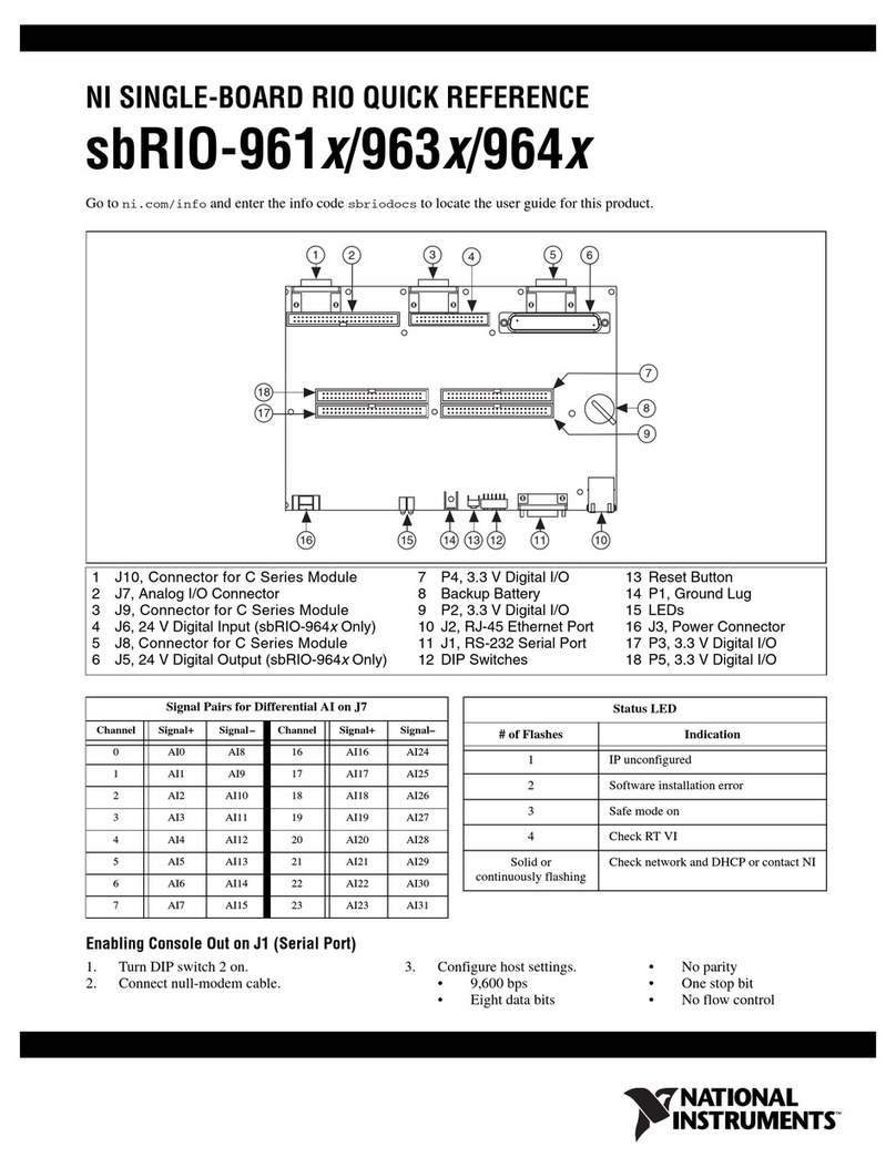
Table 2. NI sbRIO Connector Descriptions
Connector Description Manufacturer, Part
Number
Recommended
Mating
Connector
NI
Solution
Power 2-position, mini-fit JR,
H = 10.439 mm (0.411 in.)
Molex, 46999-0144 Molex,
50-36-1673 w/
0457501211
NI, Power
Plug
Assembly,
152834-01
RS-232/485/
CAN IDC
Header
10-pin, 0.100 in. CT,
shrouded,
H = 9.398 mm (0.370 in.)
Samtec,
TST-105-01-L-D
Tyco,
1658622-1
NI, 10-pin
to 9-pin
D-SUB,
153158-10
50-Pin IDC
Header
50-pin, 2 mm CT,
Shrouded,
H = 3.937 mm (0.155 in.)
Samtec,
STMM-125-02-L-D
Tyco,
2-111623-6
NI, 50-
position
ribbon
cable,
154041-12
Power Connector
The sbRIO-9637 has a power connector to which you can connect a power supply. The
following table shows the pinout for the power connector.
Table 3. Power Connector Pinout
Pinout Pin Description
V
C
Pin 1
C Common
V Power input
The sbRIO-9637 has reverse-voltage protection.
RJ-45 Gigabit Ethernet Port
The sbRIO-9637 has a tri-speed RJ-45 Gigabit Ethernet port. By default, the Ethernet port is
enabled and configured to obtain an IP address automatically. The Ethernet port can be
configured in MAX.
The following table shows the pinout for the RJ-45 Gigabit Ethernet port.
18 | ni.com | NI sbRIO-9637 User Manual
Artisan Technology Group - Quality Instrumentation ... Guaranteed | (888) 88-SOURCE | www.artisantg.com

Table 4. RJ-45 Gigabit Ethernet Port Pinout
Fast Ethernet Signal Gigabit Ethernet Signal Pin Pinout
TX+ TX_A+ 1
1
2
3
4
5
6
7
8
TX- TX_A- 2
RX+ RX_B+ 3
No Connect TX_C+ 4
No Connect TX_C- 5
RX- RX_B- 6
No Connect RX_D+ 7
No Connect RX_D- 8
Note Both Ethernet ports perform automatic crossover configuration so you do not
need to use a crossover cable to connect to a host computer.
The following NI Ethernet cables are available for the sbRIO-9637.
Table 5. RJ-45 Gigabit Ethernet Cables
Cables Length Part Number
CAT-5E Ethernet Cable, shielded 2 m 151733-02
5 m 151733-05
10 m 151733-10
RS-232 Serial Ports
The sbRIO-9637 has two RS-232 serial ports that are implemented with a shrouded header,
10-position modular jack to which you can connect devices such as displays or input devices.
Use the Serial VIs to read from and write to the serial ports. Refer to the LabVIEW Help for
information about the Serial VIs.
Find examples on how to use NI-Serial or NI-VISA to perform serial communication in the
NI Example Finder. Select Help»Find Examples in LabVIEW to launch the NI Example
Finder.
Note The ASRL1 RS-232 serial port cannot be accessed by the user application
when the Console Out startup option is enabled.
The following figure shows the pinout for the RS-232 serial ports.
NI sbRIO-9637 User Manual | © National Instruments | 19
Artisan Technology Group - Quality Instrumentation ... Guaranteed | (888) 88-SOURCE | www.artisantg.com
Table of contents
Other NI Controllers manuals

NI
NI MXI-Express Gen II x8 Series User manual

NI
NI PXI-8108 User manual

NI
NI PXI-8108 User manual

NI
NI PXIe-416 Series User manual

NI
NI VXIpc-882 User manual

NI
NI cRIO-9065 Owner's manual

NI
NI sbRIO-961 series User manual

NI
NI cRIO-9066 User manual

NI
NI cRIO-904 Series User manual

NI
NI 8352 Instruction sheet