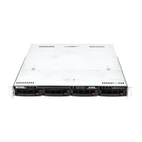
NI 8351 User manual

INSTALLATION GUIDE
NI 8351
This guide includes installation information for the NI 8351. For more
information about configuring, using, and maintaining the NI 8351, refer to
the NI 8351 User Manual. The user manual is in PDF format on the CD
included with your kit.
Contents
Related Documentation........................................................................... 2
Unpacking ............................................................................................... 2
What You Need to Get Started ............................................................... 3
Key Features ........................................................................................... 4
Mainboard Features ......................................................................... 4
CPU .......................................................................................... 4
Chipset ...................................................................................... 4
Memory .................................................................................... 4
Slots .......................................................................................... 4
Video ........................................................................................ 4
HDD.......................................................................................... 4
CD-ROM .................................................................................. 4
Onboard LAN ........................................................................... 4
Onboard I/O .............................................................................. 5
Remote Controller .................................................................... 5
Power Management Features.................................................... 5
Devices ..................................................................................... 5
Front Panel LEDs ..................................................................... 5
System Management................................................................. 5
NI 8351 Description................................................................................ 6
Optional Equipment ................................................................................ 7
Memory Upgrades ........................................................................... 7
Rack Mount Kit ............................................................................... 7
USB Floppy Disk Drive................................................................... 7
NI 8351 Overview................................................................................... 7
Safety Information .................................................................................. 8
Chassis Cooling Considerations.............................................................. 8
Providing Adequate Clearance ........................................................ 8

NI 8351 Installation Guide 2 ni.com
Installation ...............................................................................................9
Connecting Safety Ground ......................................................................9
Connecting to Power Source ...................................................................10
Rack Mounting ........................................................................................10
Drivers and Software ...............................................................................13
Files and Directories Installed on Your Hard Drive.........................13
Hard Drive Recovery...............................................................................14
Cleaning...................................................................................................14
Exterior Cleaning..............................................................................14
Where to Go for Support .........................................................................15
Related Documentation
The following documents contain information that you may find helpful as
you read this manual:
• CompactPCI Specification PICMG 2.0 R 3.0
• PXI Hardware Specification, Revision 2.1
• PXI Software Specification, Revision 2.1
• ANSI/IEEE Standard 1014-1987, IEEE Standard for a Versatile
Backplane Bus: VMEbus
• ANSI/VITA 1-1994, VME64
•NI-VISA User Manual
•NI-VISA Programmer Reference Manual
•Read Me First: Safety and Radio-Frequency Interference,
National Instruments
• NI 8351 User Manual
Unpacking
Carefully inspect the shipping container and the NI 8351 for damage.
Check for visible damage to the metal work. Check to make sure all
hardware and switches are undamaged. If damage appears to have been
caused during shipment, file a claim with the carrier. Retain the packing
material for possible inspection and/or reshipment.

©National Instruments Corporation 3 NI 8351 Installation Guide
What You Need to Get Started
The NI 8351 kit contains the following items:
❑NI 8351 rack mount controller
❑MXI-Express kit
❑NI 8351 User Manual
❑Windows recovery CD
❑NI driver CD
❑MXI-Express software CD
❑Rack mount kit
❑AC power cable (refer to Table 1 for a list of AC power cables)
If you are missing any of the above items, or if you have the incorrect
AC power cable, contact National Instruments.
Table 1. AC Power Cables
Power Cable Reference Standards
Standard 120 V (USA) ANSI C73.11/NEMA 5-15-P/IEC83
Switzerland 220 V SEV
Australia 240 V AS C112
Universal Euro 230 V CEE (7), II, IV, VII IEC83
North America 240 V ANSI C73.20/NEMA 5-15-P/IEC83
United Kingdom 230 V BS 1363/IEC83
Japan 100 V ANSI C73.11/NEMA 5-15-P/IEC83

NI 8351 Installation Guide 4 ni.com
Key Features
The NI 8351 combines the performance of a PC with a National
Instruments remote controller for PXI in a rack-mountable compact
1U form factor.
Mainboard Features
CPU
• Intel Pentium D 3.0 GHz CPU with 800 MHz FSB and 1 MB L2 cache
Chipset
• Intel E7230 chipset
• Intel ICH7R chipset
Memory
• 512 MB memory standard (2 ×256 MB ECC (32 M ×64 bit),
unbuffered, DDR-II)
• Maximum memory supported: 8 GB 533/667 DDR-II SDRAM in
4 DIMM sockets (240 pin)
Slots
• PCI Express x4 slot
Video
• ATI Radeon 7000 with 16 MB SDRAM
HDD
• 160 GB (or greater) SATA hard drive
• 3.5 in. expansion bay SATA or ATA 66/100
CD-ROM
• Slim CD-ROM drive
Onboard LAN
• Intel 82573V/L Gigabit Ethernet controller

©National Instruments Corporation 5 NI 8351 Installation Guide
Onboard I/O
• Floppy port
• PS/2 keyboard port
• PS/2 mouse port
• Serial port
• VGA port
• Parallel port
• Two USB 2.0 ports (rear)
• Two USB 2.0 ports (front)
•TwoRJ-45ports
Remote Controller
• MXI-Express interface
Power Management Features
• RTC alarm and wake up
• Wake up on LAN (WOL)
• Wake up on serial ring
• Wake up on keyboard/mouse from sleep (S1)
• Wake up on USB from sleep (S1)
• Wake up on PCI
• Supports ACPI S1/S4/S5 functions
Devices
•6×2 line LCD display panel
• Up, Enter, and Next buttons
Front Panel LEDs
•Power
• LAN activity
• HDD activity
System Management
•SMB(I
2C)
• Temperature, voltage, and fan monitors
• Chassis intrusion

NI 8351 Installation Guide 6 ni.com
NI 8351 Description
Figure 1 shows the key features of the NI 8351 front panel. For
detailed information about the NI 8351 rear panel, refer to Chapter 3,
I/O Information, in the NI 8351 User Manual.
Figure 1. Front View of the NI 8351
The front panel includes the following LEDs:
•Power indicator—glows when the NI 8351 is powered on.
•LAN status indicators—flash when there is activity on LAN1 or
LAN2.
•Hard disk in use indicator—flashes when the system is accessing
data on the hard disk.
The front panel also includes the following LCD control buttons:
•Up—Use this button to return to the previous selection.
•Enter—Use this button to execute the command.
•Next—Use this button to go to the next selection.
1 CD-ROM
2 Air Inlet
3 LCD Front Panel
4 Power Button (On/Standby)
5USBPorts
6 LCD Control Buttons
7 Power Indicator
8 LAN Status Indicator
9 Hard Disk in Use Indicator
7
8
9
6
5
123
4

©National Instruments Corporation 7 NI 8351 Installation Guide
Optional Equipment
Memory Upgrades
You can upgrade the NI 8351 memory to a maximum of 8 GB.
The NI 8351 supports dual-channel DDR-II SDRAM unbuffered memory
in four 240-pin DIMM sockets. The NI 8351 supports ECC memory.
Note National Instruments has tested and verified that the DDR-II DIMMs we sell work
with the NI 8351. We recommend you purchase your DDR-II DIMM modules from
National Instruments. Other off-the-shelf DDR-II DIMM modules are not guaranteed to
work properly.
Rack Mount Kit
A rack mount kit is included for mounting the NI 8351 chassis into a 19 in.
instrument cabinet.
USB Floppy Disk Drive
A USB floppy drive is available from National Instruments, part number
778492-02.
NI 8351 Overview
The NI 8351 is a 1U high rack-mountable PC with a remote controller for
a PXI system. It is designed for PC control of a PXI test and measurement
system using a minimum of rack space. A cable and PXI controller are
included for connection to a PXI chassis.
The NI 8351 has an Intel Pentium D processor for high performance. This
allows multithreaded software to better use the CPU. This often increases
the throughput of multithreaded applications, but single-threaded
applications may run more slowly.
The following sections describe how to install the NI 8351.
Before connecting the NI 8351 to a power source, read these sections and
the Read Me First: Safety and Radio-Frequency Interference document
included with your NI 8351.

NI 8351 Installation Guide 8 ni.com
Safety Information
Caution Before undertaking any troubleshooting, maintenance, or exploratory procedure,
carefully read the following caution notices.
This equipment contains voltage hazardous to human life and safety, and is
capable of inflicting personal injury.
•Chassis Grounding—The NI 8351 requires a connection from the
premise wire safety ground to the NI 8351 chassis ground. The earth
safety ground must be connected during use of this equipment to
minimize shock hazards. Refer to the Connecting Safety Ground
section for instructions on connecting safety ground.
•Live Circuits—Operating personnel and service personnel must not
remove protective covers when operating or servicing the NI 8351.
Adjustments and service to internal components must be undertaken
by qualified service technicians. During service of this product, the
mains connector to the premise wiring must be disconnected.
Dangerous voltages may be present under certain conditions; use
extreme caution.
•Explosive Atmosphere—Do not operate the chassis in conditions
where flammable gases are present. Under such conditions this
equipment is unsafe and may ignite the gases or gas fumes.
•Parts Replacement—Only service this equipment with parts that are
exact replacements, both electrically and mechanically. Contact
National Instruments for replacement part information. Installation of
parts with those that are not direct replacements may cause harm to
personnel operating the chassis. Furthermore, damage or fire may
occur if replacement parts are unsuitable.
•Modification—Do not modify any part of the NI 8351 from its
original condition. Unsuitable modifications may result in safety
hazards.
Chassis Cooling Considerations
The NI 8351 is designed to operate on a bench or in an instrument rack.
Determine how you want to use the NI 8351 and follow the appropriate
installation instructions.
Providing Adequate Clearance
Apertures in the front, rear, and along both sides of the chassis facilitate
power supply and motherboard cooling. Air enters through the front and
side inlets of the chassis and exits through the fans on the rear of the

©National Instruments Corporation 9 NI 8351 Installation Guide
chassis. Place the NI 8351 on a bench top or in an instrument rack so that
the fans (air outlets) and the air inlet apertures along both sides and the front
of the chassis have adequate ventilation. Keep other equipment a minimum
of 76.2 mm (3 in.) away from the air outlets on the rear of the chassis.
Installation
Follow these steps to connect devices to the NI 8351:
1. Connect a keyboard and mouse to the appropriate connectors on the
NI 8351 rear panel.
2. Connect the VGA monitor video cable to the VGA connector on the
rear panel.
3. Connect the network cable to LAN jack 1 on the rear panel.
4. Connect the USB, serial, and parallel devices as necessary to the
NI 8351 front and rear panel ports.
Caution To minimize shock hazard, make sure the electrical power outlet you use to power
the NI8351 has an appropriateearthsafetyground. Refer tothe ConnectingSafety Ground
section for more information.
5. Connect the AC power cable to the AC inlet on the rear panel and to an
AC power outlet. For more information, refer to Connecting to Power
Source section.
6. Connect the MXI-Express port on the rear of the NI 8351 to the PXI
chassis and power on the chassis.
7. Power on the NI 8351.
8. Verify that the NI 8351 boots. If it does not boot, refer to the What if
the NI 8351 does not boot? section of Chapter 5, Troubleshooting, in
the NI 8351 User Manual.
Connecting Safety Ground
The NI 8351 is designed with a three-position NEMA 5-15 style plug for
the U.S. that connects the ground line to the chassis ground. To minimize
shock hazard, make sure the electrical power outlet you use to power the
chassis has an appropriate earth safety ground.

NI 8351 Installation Guide 10 ni.com
Connecting to Power Source
Attach input power through the rear AC inlet using the appropriate
AC power cable supplied.
Caution To completely remove power, you must disconnect the AC power cable.
The power switch allows you to power on the chassis or place it in standby
mode. Push the power switch to the On position (if not already on). Observe
that all fans become operational and the power indicator is lit.
Rack Mounting
Follow these steps to rack mount the NI 8351:
1. Attach the rack mount handles to the NI 8351 front panel using the
black M4x6 screws.
1 Rack Mount Handle 2 M4x6 Screws
1
2

©National Instruments Corporation 11 NI 8351 Installation Guide
2. Attach the side rails to the sides of the NI 8351 using four M4x6 screws
on each side.
3. Attach the mounting brackets to the rack rails using M4x6 screws and
M4 nuts. The rear bracket position is adjustable; attach the rear bracket
so that it aligns with the rear rail on the rack.
1 Side Rail 2 M4x6 Screws
1 Mounting Bracket
2 M4x6 Screw
3M4Nut
4 Rack Rail
12
1 1
2
4
3 3
2

NI 8351 Installation Guide 12 ni.com
4. Attach the rack rails to the rack using the M5x8 screws and the
two-hole rack mounting plates.
5. Align the rails on the NI 8351 with the rack rails. Slide the NI 8351
halfway into the rack.
1 M5x8 Screw
2 Two-Hole Mounting Plate
3 Rack Rail
4Rack
1
3 212
4

©National Instruments Corporation 13 NI 8351 Installation Guide
6. Press the locking tabs on both sides of the NI 8351 and slide the
NI 8351 fully into the rack.
Note The locking tabs lock the NI 8351 halfway into the rack, so that it cannot slide out.
When removing the NI 8351, pull the locking tabs forward to unlock them.
7. Secure the NI 8351 to the rack with the mounting screws.
Drivers and Software
Files and Directories Installed on Your Hard Drive
Your hard drive includes a directory called images in its root that
contains software and soft copies of manuals for the peripherals. The
directory structure under the images directory is logically organized into
several levels.
In the images directory, you will find a manuals directory,
an os directory, and directories for each computer peripheral.
The manuals directory contains quick reference guides, technical
reference manuals, and National Instruments software manuals, all in
Adobe Acrobat format. To access any manual, change your directory to
c:\images\ni8351\manuals and list the contents of that directory. You
will see several files, one corresponding to each peripheral.
The os directory contains a subdirectory corresponding to the operating
system installed on your computer.
The rest of the directories correspond to each peripheral in your system.
Within these directories are the peripheral drivers. These files and
1 Locking Tab
1

NI 8351 Installation Guide 14 ni.com
directories are copied exactly from the manufacturer distribution disks, so
the naming conventions vary from peripheral to peripheral.
Hard Drive Recovery
The NI 8351 includes two methods of restoring the original factory
condition of your hard drive. Hard drive-based recovery stores a factory
backup on a separate part of your hard drive, allowing you to restore your
controller without additional media. The NI 8351 also ships with an OS
Recovery CD that allows you to reinstall your operating system onto your
hard drive via an external CD-ROM. For more information about these
tools, refer to KnowledgeBase 2ZKC02OK at ni.com/support.
Note Recovering the OS erases the contents of your hard disk. Back up any files you want
to keep.
Cleaning
Caution Always disconnect the AC power cable before cleaning or servicing the chassis.
Exterior Cleaning
Cautions Avoid getting moisture inside the chassis during exterior cleaning, especially
through the top vents.
Do not wash the front- or rear-panel connectors or switches. Cover these components while
cleaning the chassis.
Do not use harsh chemical cleaning agents; they may damage the chassis. Avoid chemicals
that contain benzene, toluene, xylene, acetone, or similar solvents.
Clean the exterior surfaces of the chassis with a dry lint-free cloth or a
soft-bristle brush. Do not use abrasive compounds on any part of the
chassis.

©National Instruments Corporation 15 NI 8351 Installation Guide
Where to Go for Support
The National Instruments Web site is your complete resource for technical
support. At ni.com/support you have access to everything from
troubleshooting and application development self-help resources to email
and phone assistance from NI Application Engineers.
National Instruments corporate headquarters is located at
11500 North Mopac Expressway, Austin, Texas, 78759-3504.
National Instruments also has offices located around the world to help
address your support needs. For telephone support in the United States,
create your service request at ni.com/support and follow the calling
instructions or dial 512 795 8248. For telephone support outside the United
States, contact your local branch office:
Australia 1800 300 800, Austria 43 0 662 45 79 90 0,
Belgium 32 0 2 757 00 20, Brazil 55 11 3262 3599,
Canada 800 433 3488, China 86 21 6555 7838,
Czech Republic 420 224 235 774, Denmark 45 45 76 26 00,
Finland 385 0 9 725 725 11, France 33 0 1 48 14 24 24,
Germany 49 0 89 741 31 30, India 91 80 41190000,
Israel 972 0 3 6393737, Italy 39 02 413091, Japan 81 3 5472 2970,
Korea 82 02 3451 3400, Lebanon 961 0 1 33 28 28,
Malaysia 1800 887710, Mexico 01 800 010 0793,
Netherlands 31 0 348 433 466, New Zealand 0800 553 322,
Norway 47 0 66 90 76 60, Poland 48 22 3390150,
Portugal 351 210 311 210, Russia 7 095 783 68 51,
Singapore 1800 226 5886, Slovenia 386 3 425 4200,
South Africa 27 0 11 805 8197, Spain 34 91 640 0085,
Sweden 46 0 8 587 895 00, Switzerland 41 56 200 51 51,
Taiwan 886 02 2377 2222, Thailand 662 278 6777,
United Kingdom 44 0 1635 523545

National Instruments, NI, ni.com, and LabVIEW are trademarks of National Instruments Corporation.
Refer to the Terms of Use section on ni.com/legal for more information about National
Instruments trademarks. Other product and company names mentioned herein are trademarks or trade
names of their respective companies. For patents covering National Instruments products, refer to the
appropriate location: Help»Patents in your software, the patents.txt file on your CD, or
ni.com/patents.
© 2006 National Instruments Corporation. All rights reserved. 371895A-01 Mar06
Table of contents
Other NI Controllers manuals