NI cRIO-9066 User manual
GETTING STARTED GUIDE
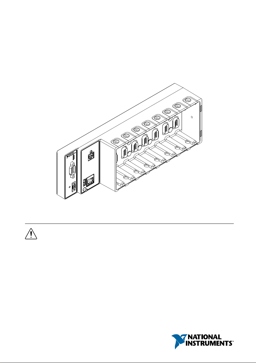
NI cRIO-9066
Embedded Real-Time Controller with Reconfigurable FPGA for C
Series Modules
This document describes how to begin using the NI cRIO-9066.
Safety Guidelines
Caution Do not operate the cRIO-9066 in a manner not specified in this document.
Product misuse can result in a hazard. You can compromise the safety protection
built into the product if the product is damaged in any way. If the product is
damaged, return it to NI for repair.
Safety Guidelines for Hazardous Locations
The cRIO-9066 is suitable for use in Class I, Division 2, Groups A, B, C, D, T4 hazardous
locations; Class I, Zone 2, AEx nA IIC T4 and Ex nA IIC T4 hazardous locations; and
nonhazardous locations only. Follow these guidelines if you are installing the cRIO-9066 in a
potentially explosive environment. Not following these guidelines may result in serious injury
or death.
Caution Do not disconnect the power supply wires and connectors from the
controller unless power has been switched off.
Caution Do not disconnect I/O-side wires or connectors unless power has been
switched off or the area is known to be nonhazardous.
Caution Do not remove modules unless power has been switched off or the area is
known to be nonhazardous.
Caution Substitution of components may impair suitability for Class I, Division 2.
Caution For Division 2 and Zone 2 applications, install the system in an enclosure
rated to at least IP54 as defined by IEC/EN 60079-15.
Caution The USB ports require the retention accessories listed in the following
table for hazardous locations. All cables must be used in a conduit or cable gland to
wire to a nonhazardous location. Do not disconnect a cable unless the cRIO-9066 is
powered off or the area is known to be nonhazardous.
Table 1. Hazardous Location Retention Accessories
Port Required Accessory Part Number
USB Device Port NI Locking USB Cable 157788-01
USB Host Port NI Industrial USB Extender Cable 152166-xx
Special Conditions for Hazardous Locations Use in Europe and
Internationally
The cRIO-9066 has been evaluated as Ex nA IIC T4 Gc equipment under DEMKO Certificate
No. 12 ATEX 1202658X and is IECEx UL 14.0089X certified. Each device is marked II
3G and is suitable for use in Zone 2 hazardous locations, in ambient temperatures of -20 °C ≤
Ta ≤ 55 °C.
Caution You must make sure that transient disturbances do not exceed 140% of
the rated voltage.
Caution The system shall only be used in an area of not more than Pollution
Degree 2, as defined in IEC 60664-1.
Caution The system shall be mounted in an ATEX/IECEx-certified enclosure with
a minimum ingress protection rating of at least IP54 as defined in IEC/EN 60079-15.
Caution The enclosure must have a door or cover accessible only by the use of a
tool.
2| ni.com | NI cRIO-9066 Getting Started Guide

Electromagnetic Compatibility Guidelines
This product was tested and complies with the regulatory requirements and limits for
electromagnetic compatibility (EMC) stated in the product specifications. These requirements
and limits provide reasonable protection against harmful interference when the product is
operated in the intended operational electromagnetic environment.
This product is intended for use in industrial locations. However, harmful interference may
occur in some installations, when the product is connected to a peripheral device or test object,
or if the product is used in residential or commercial areas. To minimize interference with
radio and television reception and prevent unacceptable performance degradation, install and
use this product in strict accordance with the instructions in the product documentation.
Furthermore, any changes or modifications to the product not expressly approved by National
Instruments could void your authority to operate it under your local regulatory rules.
Caution To ensure the specified EMC performance, operate this product only with
shielded cables and accessories.
Special Conditions for Marine Applications
Some products are Lloyd’s Register (LR) Type Approved for marine (shipboard) applications.
To verify Lloyd’s Register certification for a product, visit ni.com/certification and search for
the LR certificate, or look for the Lloyd’s Register mark on the product.
Caution In order to meet the EMC requirements for marine applications, install the
product in a shielded enclosure with shielded and/or filtered power and input/output
ports. In addition, take precautions when designing, selecting, and installing
measurement probes and cables to ensure that the desired EMC performance is
attained.
Preparing the Environment
Ensure that the environment in which you are using the cRIO-9066 meets the following
specifications.
Operating temperature
(IEC 60068-2-1, IEC 60068-2-2)
-20 °C to 55 °C
Operating humidity (IEC 60068-2-56) 10% RH to 90% RH, noncondensing
Pollution degree 2
Maximum altitude 5,000 m
NI cRIO-9066 Getting Started Guide | © National Instruments | 3
Indoor use only.
Note Refer to the device specifications on ni.com/manuals for complete
specifications.
Unpacking the Kit
Caution To prevent electrostatic discharge (ESD) from damaging the device,
ground yourself using a grounding strap or by holding a grounded object, such as
your computer chassis.
1. Touch the antistatic package to a metal part of the computer chassis.
2. Remove the device from the package and inspect the device for loose components or any
other sign of damage.
Caution Never touch the exposed pins of connectors.
Note Do not install a device if it appears damaged in any way.
3. Unpack any other items and documentation from the kit.
Store the device in the antistatic package when the device is not in use.
Verifying the Kit Contents
Verify that the following items are included in the cRIO-9066 kit.
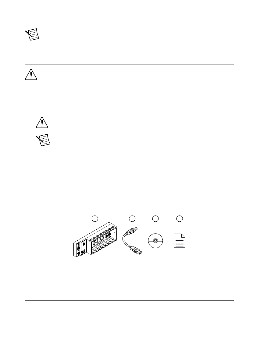
Figure 1. cRIO-9066 Kit Contents
24
3
1
1. cRIO Device
2. USB A-to-B Cable
3. NI CompactRIO Device Drivers Media
4. Getting Started Guide
Installing Software on the Host Computer
Before using the cRIO-9066, you must install the following application software and device
drivers on the host computer in this order:
1. LabVIEW 2014 or later
2. LabVIEW Real-Time Module 2014 or later
4| ni.com | NI cRIO-9066 Getting Started Guide

3. LabVIEW FPGA Module 2014 or later1
4. NI-RIO Device Drivers 15.0 or later
For minimum software support information, visit ni.com/info and enter the Info Code
swsupport.
Installing C Series Modules
Complete the following steps to install a C Series module.
2
2
3
1
1. Verify that power is not connected to the I/O connector(s) on the C Series module. If the
system is in a nonhazardous location, the cRIO-9066 can be powered on when you install
modules.
2. Press the latches on the C Series module.
3. Align the C Series module with a slot and seat it in the slot until the latches lock in place.
Removing C Series Modules
Verify that power is not connected to the I/O connector(s) on the C Series module before you
remove a module from the cRIO-9066. If the system is in a nonhazardous location, the
cRIO-9066 can be powered on when you remove modules.
Connecting the cRIO-9066
The cRIO-9066 has the following connectors, LEDs, and buttons.
1LabVIEW FPGA Module is not required when using Scan Interface mode. To program the user-
accessible FPGA on the cRIO-9066, LabVIEW FPGA Module is required.
NI cRIO-9066 Getting Started Guide | © National Instruments | 5
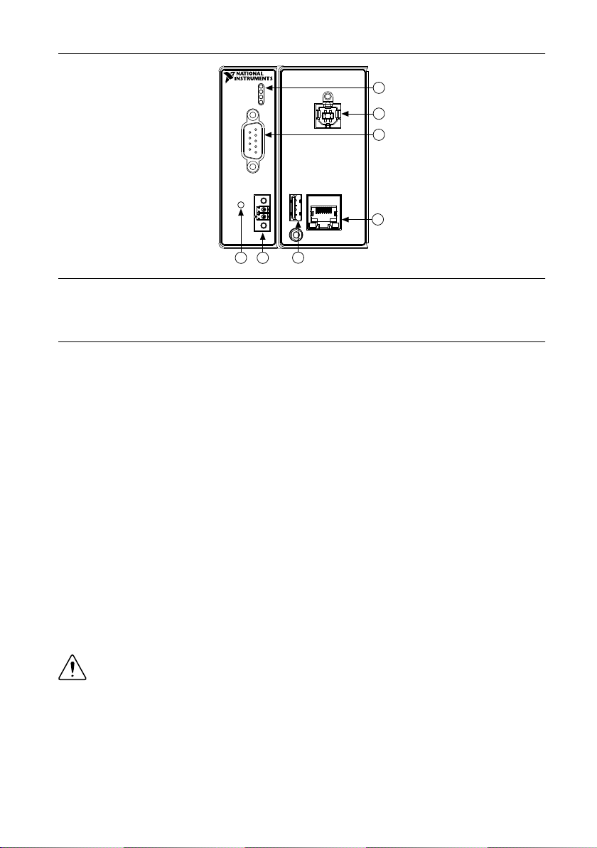
Figure 2. cRIO-9066 Front Panel
6
7
2
4
1
5
3
1. LEDs
2. USB Device Port
3. RS-232 Serial Port
4. RJ-45 Ethernet Port 1
5. USB Host Port
6. Power Connector
7. RESET Button
Connecting the cRIO-9066 to Ground
You must connect the cRIO-9066 grounding terminal to the grounding electrode system of the
facility.
What to Use
• Ring lug
• Wire, 2.1 mm2 (14 AWG) or larger
• Screwdriver, Phillips #2
What to Do
Complete the following steps to ground the cRIO-9066.
1. Attach the ring lug to the wire.
2. Remove the grounding screw from the grounding terminal on the cRIO-9066.
3. Attach the ring lug to the grounding terminal.
4. Tighten the grounding screw to 0.5 N · m (4.4 lb · in.) of torque.
5. Attach the other end of the wire to the grounding electrode system of your facility using a
method that is appropriate for your application.
Caution If you use shielded cabling to connect to a C Series module with a plastic
connector, you must attach the cable shield to the chassis grounding terminal using
2.1 mm2 (14 AWG) or larger wire. Attach a ring lug to the wire and attach the wire
to the chassis grounding terminal. Solder the other end of the wire to the cable
shield. Use shorter wire for better EMC performance.
For more information about ground connections, visit ni.com/info and enter the Info Code
emcground.
6| ni.com | NI cRIO-9066 Getting Started Guide
Connecting the cRIO-9066 to Power
The cRIO-9066 requires a 9 V to 30 V external power supply. The cRIO-9066 filters and
regulates the supplied power and provides power for the C Series modules. The cRIO-9066
has one layer of reverse-voltage protection.
The following table lists the POWER LED indicators.
Table 2. POWER LED Indicators
LED Color LED Pattern Indication
Green Solid The cRIO-9066 is powered on and the connected power supply is
adequate.
— Off The cRIO-9066 is powered off.
What to Use
• Screwdriver, 2.54 mm (0.10 in.) flathead
• Power supply, 9 V to 30 V, 25 W maximum
NI recommends the power supply listed in the following table for the cRIO-9066.
Table 3. NI Power Supplies
Power Supply Part Number
NI PS-15 Industrial Power Supply
(24 VDC, 5 A, 100 VAC to 120 VAC/200 VAC to 240 VAC input)
781093-01
What to Do
Complete the following steps to connect a power supply to the cRIO-9066.
1. Ensure that your power supply is powered off.
2. Remove the power connector from the cRIO-9066.
Caution Do not tighten or loosen the terminal screws on the power connector
while the cRIO-9066 is powered on.
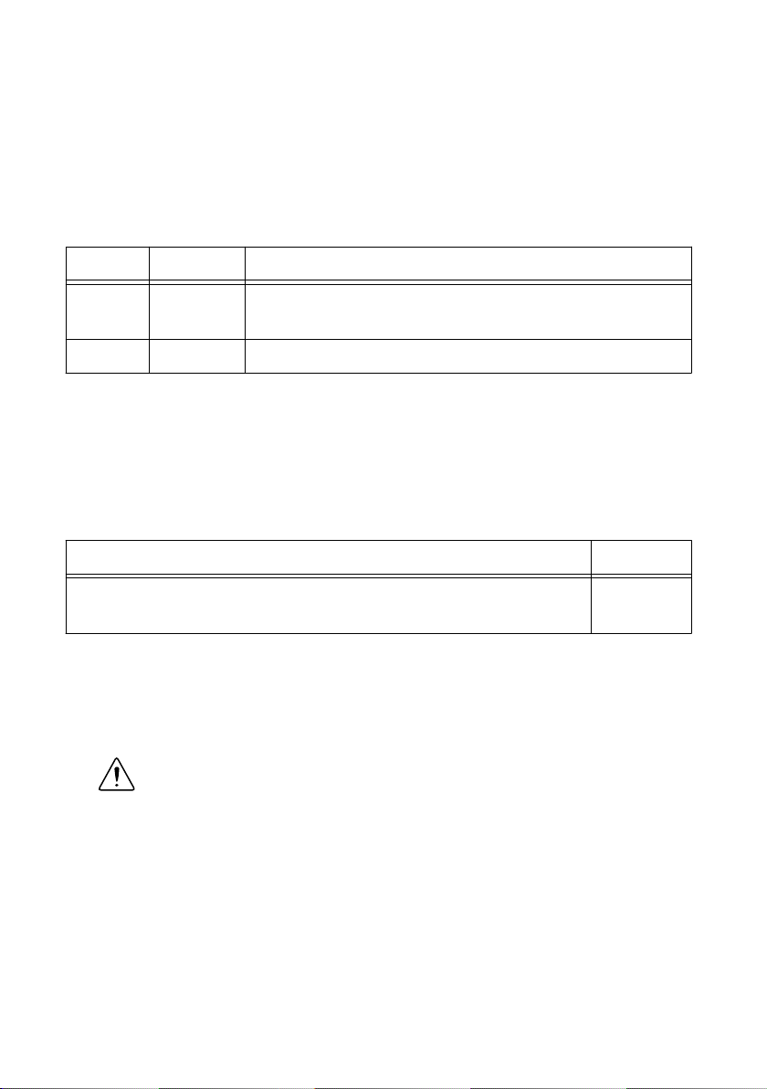
3. Connect the power supply to the power connector, as shown in the following figure.
NI cRIO-9066 Getting Started Guide | © National Instruments | 7
Figure 3. cRIO-9066 Power Connections
Power Connector
C
V
Power Supply
+
–
Note The C terminals are internally connected to each other.
4. Tighten the terminal screws on the power connector to 0.20 N · m to 0.25 N · m
(1.8 lb · in. to 2.2 lb · in.) of torque.
5. Install the power connector on the front panel of the cRIO-9066.
6. Tighten the power connector screw flanges to 0.20 N · m to 0.25 N · m (1.8 lb · in. to
2.2 lb · in.) of torque.
7. Power on the power supply.
Powering On the cRIO-9066
When you power on the cRIO-9066 for the first time, the device boots into safe mode. The
POWER LED illuminates, the STATUS LED illuminates briefly, and then the STATUS LED
blinks twice every few seconds.
Connecting the cRIO-9066 to the Host Computer
Complete the following steps to connect the cRIO-9066 to the host computer using the USB
device port.
1. Power on the host computer.
2. Connect the cRIO-9066 to the host computer using the USB A-to-B cable.
Caution NI requires the use of a locking USB cable (157788-01) to meet the
shock and vibration specifications. Refer to the specifications on ni.com/
manuals for shock and vibration specifications.
The device driver software automatically detects the cRIO-9066. If the device driver
software does not detect the cRIO-9066, verify that you installed the appropriate NI
software in the correct order on the host computer.
Tip You can also use the Ethernet port to connect directly to the host computer or
network. Refer to the user manual on ni.com/manuals for more information about
Ethernet connections.
Configuring the System in Measurement &
Automation Explorer (MAX)
Complete the following steps to find the system in MAX.
8| ni.com | NI cRIO-9066 Getting Started Guide

1. Launch MAX on the host computer.
2. Expand Remote Systems in the configuration tree and locate your system.
3. Select your target.
Tip MAX lists the system under the model number followed by the serial
number, such as NI-CRIO-9066-1856AAA.
Setting a System Password
Complete the following steps to set a system password.
Note The default username for the cRIO-9066 is admin. There is no default
password for the cRIO-9066, so you must leave the password field blank when
logging in until you set a system password.
1. Right-click your system and select Web Configuration.
The NI Web-Based Configuration and Monitoring utility opens in your default browser
and is where you set the password. If you have not installed Microsoft Silverlight,
NI Web-based Configuration & Monitoring prompts you to do so.
2. Enter a unique name for your system in the Hostname field.
3. Click the Security Configuration icon.
4. Click Login.
5. In the Login dialog box, enter the username admin and leave the password field blank.
6. Click OK.
7. Click Change Password.
8. Enter and re-enter a new password.
9. Click OK.
10. Click Save.
11. Click OK to confirm you are changing the password.
Caution NI cannot recover lost system passwords. If you forget the password,
you must contact NI and reformat the controller.
Installing Software on the cRIO-9066
Complete the following steps to install software on the cRIO-9066.
1. In MAX, expand your system under Remote Systems.
2. Right-click Software.
3. Select Add/Remove Software to launch the LabVIEW Real-Time Software Wizard.
Tip You must log in if you set a system password.
4. Select the recommended software set for your LabVIEW and NI-RIO Device Drivers
versions.
5. Click Next.
NI cRIO-9066 Getting Started Guide | © National Instruments | 9

6. Select NI Scan Engine from the software add-ons.
Select any additional software to install. If you plan on using the cRIO-9066 with the
LabVIEW FPGA Module, you can click Next. Click NI Scan Engine if you plan on
using the cRIO-9066 without the LabVIEW FPGA Module.
Tip You can use this wizard at anytime to install additional software.
7. Click Next.
8. Verify that the summary of software to install is correct.
9. Click Next to start the installation.
10. Click Finish when the installation is complete.
Troubleshooting the cRIO-9066
The cRIO-9066 is Not Communicating with the
Network
• Ensure that the USB connections between the cRIO-9066 and the host computer and the
Ethernet connections between the host computer and the router are secure.
• Configure the IP and other network settings by completing the following steps.
1. Use a USB A-to-B cable to connect the cRIO-9066 USB device port to a host
computer. The USB driver creates a virtual network interface card and assigns an IP
address to the cRIO-9066 in the format of 172.22.11.x.
2. In MAX, expand your system under Remote Systems.
3. Select the Network Settings tab to configure the IP and other network settings.
4. (Optional) Use the RJ-45 Ethernet port 1 to reconnect the cRIO-9066 to the host
computer. The cRIO-9066 attempts to initiate a DHCP network connection at
powerup.
Note If the cRIO-9066 cannot obtain an IP address, it connects to the
network with a link-local IP address with the form 169.254.x.x. The host
computer communicates with the cRIO-9066 over a standard Ethernet
connection.
• Ensure that you have the correct version of NI-RIO Device Drivers installed on the host
computer. Visit ni.com/info and enter the Info Code swsupport for the minimum
supported versions of LabVIEW and NI-RIO Device Drivers.
Tip If you have recently upgraded LabVIEW, you must reinstall NI-RIO
Device Drivers.
• Ensure that the NI USBLAN adapter is recognized in the Device Manager. On
Windows 7, select Start»Control Panel»Device Manager»Network adapters»National
Instruments»USBLAN adapter. If the USBLAN adapter is not recognized, you must
reinstall NI-RIO Device Drivers.
• Temporarily disable any network firewalls or other security software.
10 | ni.com | NI cRIO-9066 Getting Started Guide
Other manuals for cRIO-9066
1
Table of contents
Other NI Controllers manuals


Popular Controllers manuals by other brands

Digiplex
Digiplex DGP-848 Programming guide

YASKAWA
YASKAWA SGM series user manual

Sinope
Sinope Calypso RM3500ZB installation guide

Isimet
Isimet DLA Series Style 2 Installation, Operations, Start-up and Maintenance Instructions

LSIS
LSIS sv-ip5a user manual

Airflow
Airflow Uno hab Installation and operating instructions


