NI cRIO-9066 User manual

USER MANUAL
NI cRIO-9066
Embedded Real-Time Controller with Reconfigurable FPGA for
C Series Modules
This document describes the features of the NI cRIO-9066 and contains information about
mounting and operating the device.
RJ-45
Ethernet1
256 MB
DDR3
512 MB
NAND Flash
GigE
MAC/PHY Xilinx Zynq-7000
XC7Z020
All-Programmable SoC
++
++
RGMII ONFI
NI cRIO-9066
Hardware
Data
C Series
Module
C Series
Module
USB 2.0 Host Port
USB 2.0 Device Port
RS-232 Serial Port
Contents
Configuring the cRIO-9066...................................................................................................... 2
Connecting the cRIO-9066 to the Host Computer or Network Using Ethernet............... 2
Configuring Startup Options.............................................................................................3
cRIO-9066 Features.................................................................................................................. 4
Ports and Connectors........................................................................................................ 4
Buttons.............................................................................................................................. 9
LEDs................................................................................................................................11
Chassis Grounding Screw............................................................................................... 13
Internal Real-Time Clock................................................................................................14
Battery.............................................................................................................................14
File System......................................................................................................................14

Mounting the Device...............................................................................................................15
Dimensions......................................................................................................................15
Mounting Requirements..................................................................................................16
Ambient Temperature......................................................................................................17
Mounting the Device Directly on a Flat Surface............................................................ 17
Mounting the Device on a Panel..................................................................................... 18
Mounting the Device on a DIN Rail............................................................................... 20
Mounting the Device on a Rack......................................................................................21
Mounting the Device on a Desktop.................................................................................21
Worldwide Support and Services............................................................................................ 24
Configuring the cRIO-9066
You can connect the cRIO-9066 to a host computer or network and configure the startup
options using the USB device port or the RJ-45 Gigabit Ethernet port 1.
Tip Refer to the getting started guide on ni.com/manuals for basic configuration
instructions and information about connecting to a host computer using the USB
device port. NI recommends using the USB device port for configuration, debug,
and maintenance.
Connecting the cRIO-9066 to the Host Computer or
Network Using Ethernet
Complete the following steps to connect the cRIO-9066 to a host computer or Ethernet
network using the RJ-45 Gigabit Ethernet port 1. NI recommends using the RJ-45 Gigabit
Ethernet port 1 for communication with deployed systems.
1. Power on the host computer or Ethernet hub.
2. Connect the RJ-45 Gigabit Ethernet port 1 on the cRIO-9066 to the host computer or
Ethernet hub using a standard Category 5 (CAT-5) or better shielded, twisted-pair
Ethernet cable.
Caution To prevent data loss and to maintain the integrity of your Ethernet
installation, do not use a cable longer than 100 m (328 ft).
The cRIO-9066 attempts to initiate a DHCP network connection the first time you
connect using Ethernet. The cRIO-9066 connects to the network with a link-local IP
address with the form 169.254.x.x if it is unable to initiate a DHCP connection.
Finding the cRIO-9066 on the Network (DHCP)
Complete the following steps to find the cRIO-9066 on a network using DHCP.
1. Disable secondary network interfaces on the host computer, such as a wireless access
card on a laptop.
2| ni.com | NI cRIO-9066 User Manual

2. Ensure that any anti-virus and firewall software running on the host computer allows
connections to the host computer.
Note MAX uses UDP 44525. Refer to the documentation of your firewall
software for information about configuring the firewall to allow communication
through the UDP 44525.
3. Launch MAX on the host computer.
4. Expand Remote Systems in the configuration tree and locate your system.
Tip MAX lists the system under the model number followed by the serial
number, such as NI-cRIO-9066-1856AAA.
Configuring Startup Options
Complete the following steps to configure the cRIO-9066 startup options in MAX.
1. In MAX, expand your system under Remote Systems.
2. Select the Startup Settings tab to configure the startup settings.
cRIO-9066 Startup Options
You can configure the following cRIO-9066 startup options.
Table 1. cRIO-9066 Startup Options
Startup Option Description
Force Safe Mode Rebooting the cRIO-9066 with this setting on starts the cRIO-9066
without launching LabVIEW Real-Time or any startup applications. In
safe mode, the cRIO-9066 launches only the services necessary for
updating configuration and installing software.
Enable Console
Out
Rebooting the cRIO-9066 with this setting on redirects the console output
to the RS-232 serial port. You can use a serial-port terminal program to
read the IP address and firmware version of the cRIO-9066. Use a null-
modem cable to connect the RS-232 serial port to a computer. Make sure
that the serial-port terminal program is configured to the following
settings:
• 115,200 bits per second
• Eight data bits
• No parity
• One stop bit
• No flow control
Disable RT
Startup App
Rebooting the cRIO-9066 with this setting on prevents any LabVIEW
startup applications from running.
NI cRIO-9066 User Manual | © National Instruments | 3

Table 1. cRIO-9066 Startup Options (Continued)
Startup Option Description
Disable FPGA
Startup App
Rebooting the cRIO-9066 with this setting on prevents autoloading of any
FPGA application.
Note When you reset the cRIO-906x controller either
programmatically or by using the RESET button, you also reset
the FPGA. All FPGA I/O lines are tri-stated after a reset, and
will enter predefined states once loaded.
Enable Secure
Shell (SSH)
Logins
Rebooting the cRIO-9066 with this setting on starts sshd on the
cRIO-9066. Starting sshd enables logins over SSH, an encrypted
communication protocol.
Note Visit ni.com/info and enter the Info Code openssh for
more information about SSH.
LabVIEW
Project Access
Rebooting the cRIO-9066 with this setting on enables you to add the
target to a LabVIEW project.
cRIO-9066 Features
The cRIO-9066 provides the following features.
Ports and Connectors
The cRIO-9066 provides the following ports and connectors.
4| ni.com | NI cRIO-9066 User Manual

Figure 1. cRIO-9066 Ports and Connectors
1
2
45
3
1. USB Device Port
2. RS-232 Serial Port
3. RJ-45 Ethernet Port 1
4. USB Host Port
5. Power Connector
RJ-45 Gigabit Ethernet Port
The cRIO-9066 has one tri-speed RJ-45 Gigabit Ethernet port. By default, the Ethernet port is
enabled and configured to obtain an IP address automatically. The Ethernet port can be
configured in MAX.
The following table shows the pinout for the RJ-45 Gigabit Ethernet port.
NI cRIO-9066 User Manual | © National Instruments | 5
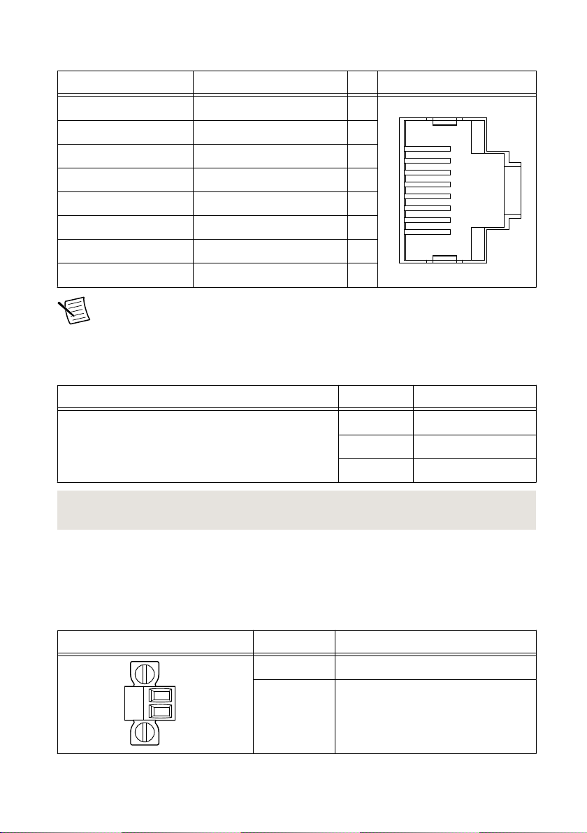
Table 2. RJ-45 Gigabit Ethernet Port Pinout
Fast Ethernet Signal Gigabit Ethernet Signal Pin Pinout
TX+ TX_A+ 1
1
2
3
4
5
6
7
8
TX- TX_A- 2
RX+ RX_B+ 3
No Connect TX_C+ 4
No Connect TX_C- 5
RX- RX_B- 6
No Connect RX_D+ 7
No Connect RX_D- 8
Note The Ethernet port performs automatic crossover configuration so you do not
need to use a crossover cable to connect to a host computer.
The following NI Ethernet cables are available for the cRIO-9066.
Table 3. RJ-45 Gigabit Ethernet Cables
Cables Length Part Number
CAT-5E Ethernet Cable, shielded 2 m 151733-02
5 m 151733-05
10 m 151733-10
Related Information
Ethernet LED Indicators on page 13
Power Connector
The cRIO-9066 has a power connector to which you can connect a power supply. The
following table shows the pinout for the power connector.
Table 4. Power Connector Pinout
Pinout Pin Description
V
C
V Power input
C Common
6| ni.com | NI cRIO-9066 User Manual
The cRIO-9066 has reverse-voltage protection.
The following NI power supplies and accessories are available for the cRIO-9066.
Table 5. Power Accessories
Accessory Part Number
NI PS-10 Desktop Power Supply, 24 VDC, 5 A, 100-120/200-240 VAC Input 782698-01
NI PS-14 Industrial Power Supply, 24 to 28 VDC, 3.3 A, 100-240 VAC Input 783167-01
NI PS-15 Industrial Power Supply, 24 to 28 VDC, 5 A, 100/230 VAC Input 781093-01
NI PS-16 Industrial Power Supply, 24 to 28 VDC, 10 A, 115/230 VAC Input 781094-01
NI PS-17 Industrial Power Supply, 24 to 28 VDC, 20 A, 85-276 VAC Input 781095-01
Related Information
POWER LED Indicators on page 11
RS-232 Serial Port
The cRIO-9066 has an RS-232 serial port to which you can connect devices such as displays
or input devices. Use the Serial VIs to read from and write to the serial port. Refer to the
LabVIEW Help for information about the Serial VIs.
Find examples on how to use NI-Serial or NI-VISA to perform serial communication in the
NI Example Finder. The NI Example Finder is located on the Help menu in the LabVIEW
Help.
Note The RS-232 serial port cannot be accessed by the user application when the
Console Out startup option is enabled.
The following table shows the pinout for the RS-232 serial port.
NI cRIO-9066 User Manual | © National Instruments | 7
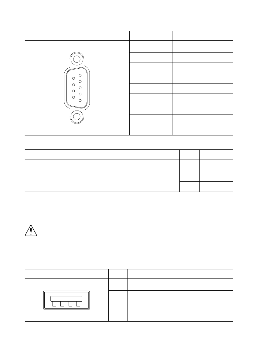
Table 6. RS-232 Serial Port Pinout
Pinout Pin Signal
1
2
3
4
5
6
7
8
9
1 DCD
2 RxD
3 TxD
4 DTR
5 GND
6 DSR
7 RTS
8 CTS
9 RI
Table 7. RS-232 Serial Port Accessories
Accessory Length Part Number
RS-232, Null-Modem Serial Cable, 9-Pin DSUB (Female) to 9-Pin
DSUB (Female)
1 m 182238-01
2 m 182238-02
4 m 182238-04
USB Host Ports
The USB host ports on the cRIO-9066 support common USB mass-storage devices such as
USB Flash drives, USB-to-IDE adapters, keyboards, mice, and USB cameras.
Caution Do not hot-swap USB devices while the cRIO-9066 is in a hazardous
location or connected to high voltages. If the cRIO-9066 is not in a hazardous
location, you can connect and disconnect USB devices without affecting operation.
The following table shows the pinout for the USB host ports.
Table 8. USB Host Port Pinout
Pinout Pin Signal Description
1
42
3
1 VCC Cable power (5 V)
2 D- USB data-
3 D+ USB data+
4 GND Ground
The following NI cable is available for the cRIO-9066.
8| ni.com | NI cRIO-9066 User Manual
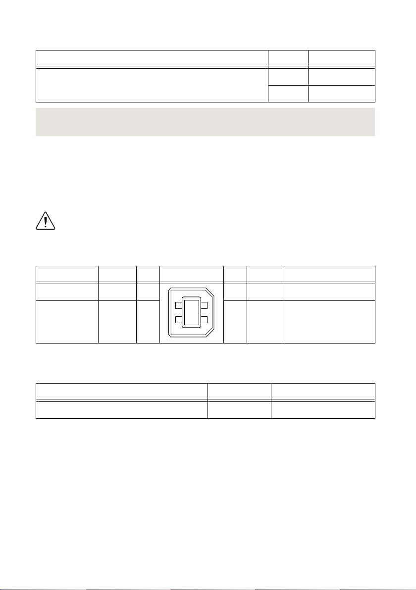
Table 9. USB Host Port Cable
Cable Length Part Number
USB Extension with Retention, Type A Connectors 0.5 m 152166-0R5
2 m 152166-02
Related Information
File System on page 14
USB Device Port
The cRIO-9066 USB device port is intended for device configuration, application deployment,
debugging, and maintenance. For example, you can use the USB device port to install software
or driver updates during field maintenance instead of interrupting communication on the RJ-45
Ethernet ports.
Caution Do not hot-swap USB devices while the cRIO-9066 is in a hazardous
location or connected to high voltages. If the cRIO-9066 is not in a hazardous
location, you can connect and disconnect USB devices without affecting operation.
The following table shows the pinout for the USB device port.
Description Signal Pin Pinout Pin Signal Description
USB data+ D+ 3
1
4
2
3
2 D- USB data-
Ground GND 4 1 VCC Cable power (5 V)
The following NI cable is available for the cRIO-9066.
Table 10. USB Device Port Cable
Cable Length Part Number
NI Locking USB Cable 1 m 157788-01
Buttons
The cRIO-9066 provides the following buttons.
NI cRIO-9066 User Manual | © National Instruments | 9
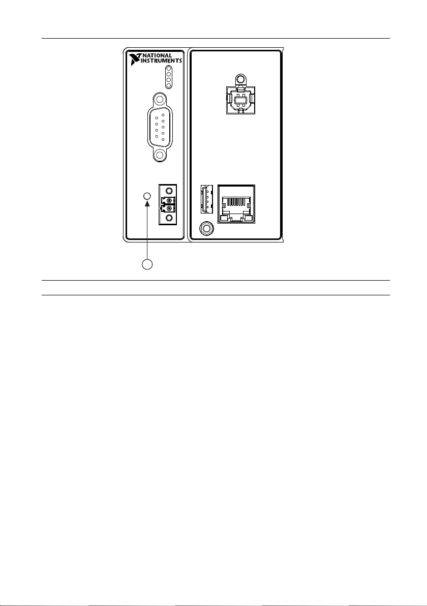
Figure 2. cRIO-9066 Buttons
1
1. RESET Button
RESET Button
Press the RESET button to reset the processor in the same manner as cycling power.
Troubleshooting Network Connectivity
You can use the RESET button to troubleshoot network connectivity.
Complete the following steps to reset the network adapters to default settings.
1. Hold the RESET button for 5 seconds, and then release it to boot the controller in safe
mode and enable Console Out.
2. Hold the RESET button again for 5 seconds to boot the controller into safe mode, enable
Console Out, and reset network adapters to default settings.
System Reset
The following figure shows the reset behavior of the cRIO-9066.
10 | ni.com | NI cRIO-9066 User Manual
Other manuals for cRIO-9066
1
Table of contents
Other NI Controllers manuals


Popular Controllers manuals by other brands

Digiplex
Digiplex DGP-848 Programming guide

YASKAWA
YASKAWA SGM series user manual

Sinope
Sinope Calypso RM3500ZB installation guide

Isimet
Isimet DLA Series Style 2 Installation, Operations, Start-up and Maintenance Instructions

LSIS
LSIS sv-ip5a user manual

Rockwell Automation
Rockwell Automation 1769-L31 installation instructions


