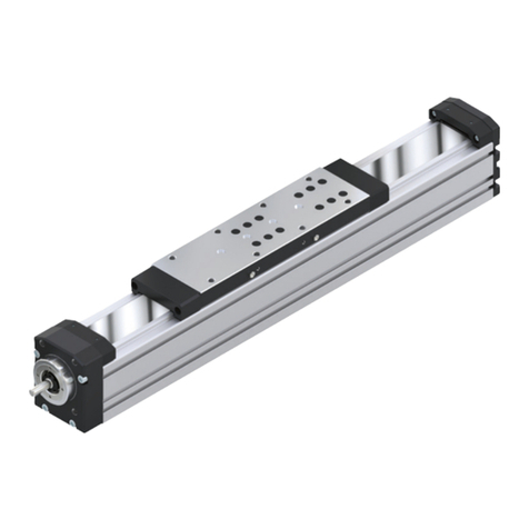
Bosch Rexroth VT-MRMA1-1 User manual
Other Bosch Control Unit manuals

Bosch
Bosch CL400 User manual

Bosch
Bosch PBK User manual
Bosch
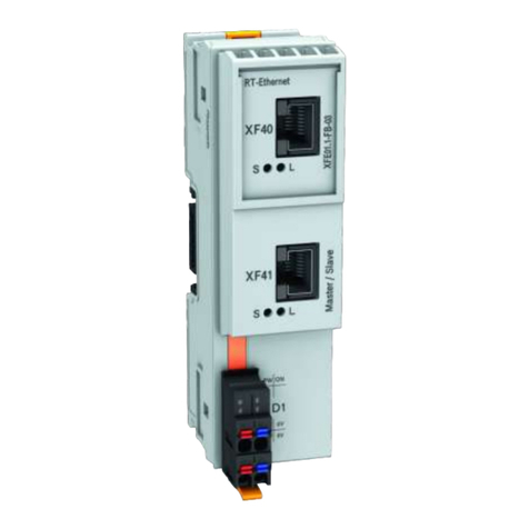
Bosch Rexroth IndraControl XFE 01.1 Series User manual
Bosch
Bosch RM2-DP12 Operating and installation instructions
Bosch
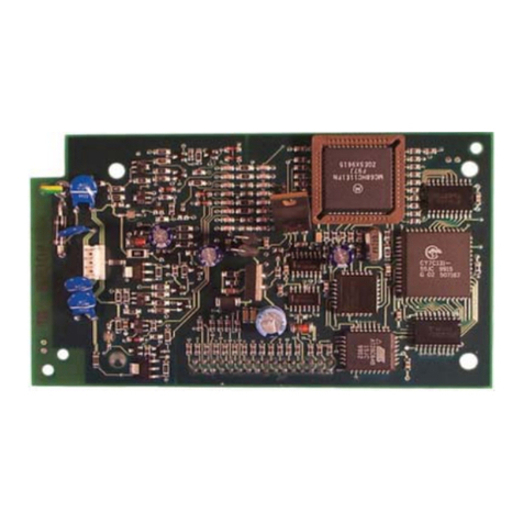
Bosch D7039 User manual
Bosch
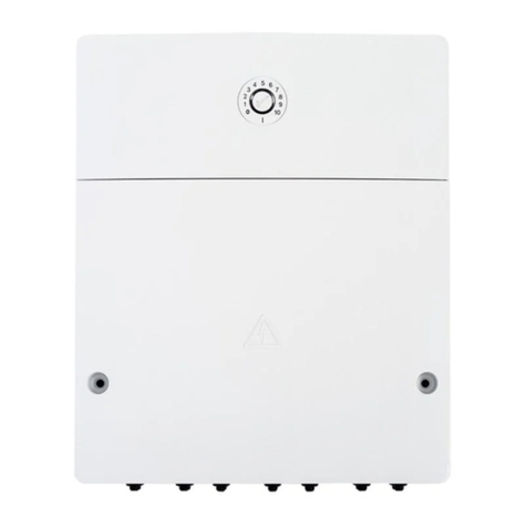
Bosch MP 100 User manual
Bosch
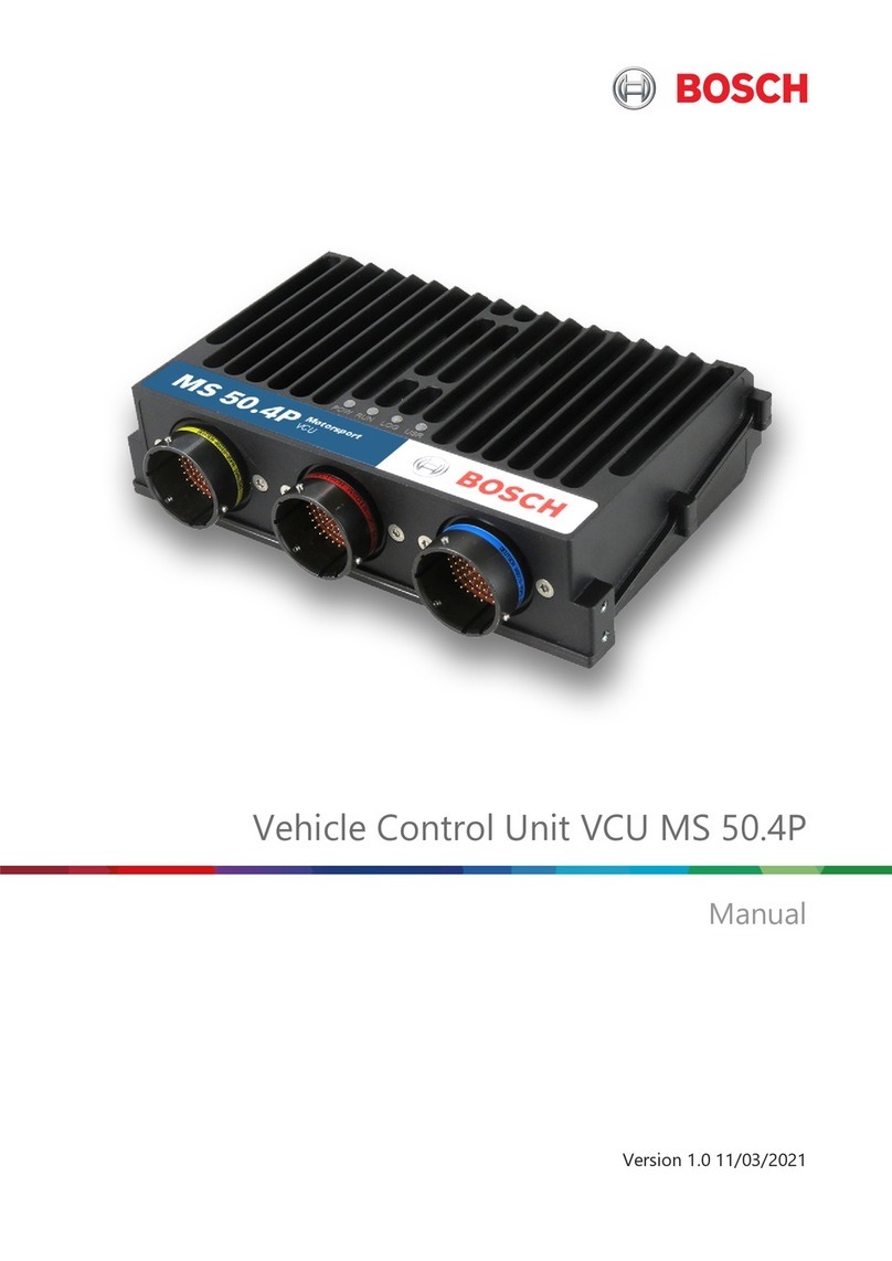
Bosch VCU MS 50.4P User manual
Bosch
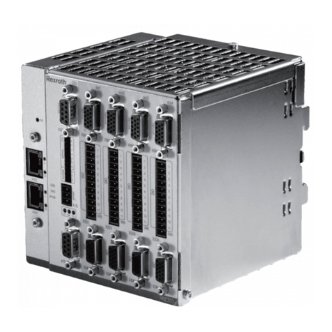
Bosch Rexroth VT-HNC100 3X Series User manual

Bosch
Bosch rexroth DBD 1X/ E Series User manual
Bosch
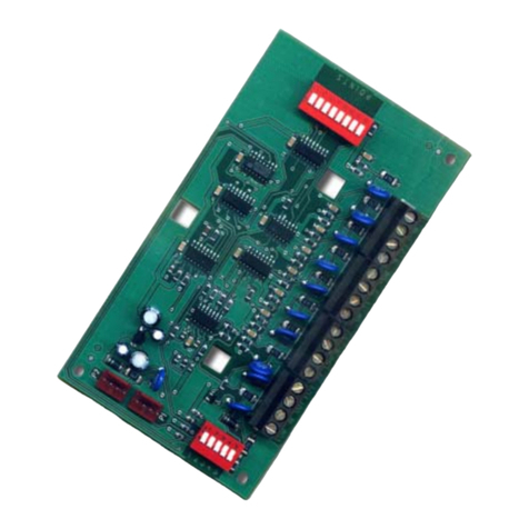
Bosch D8128D User manual
Bosch
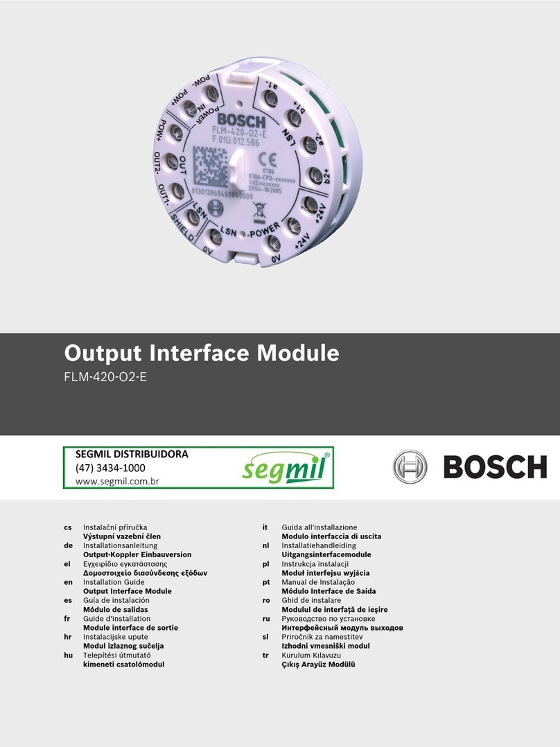
Bosch FLM-420-O2-E User manual
Bosch
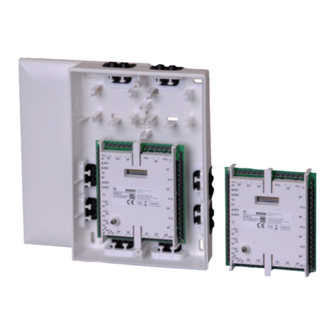
Bosch ISP-EMIL-120 User manual
Bosch
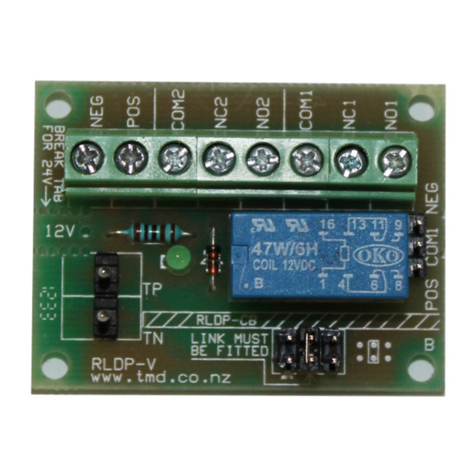
Bosch CONNECT RLDP-V User manual
Bosch
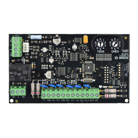
Bosch B901 User manual
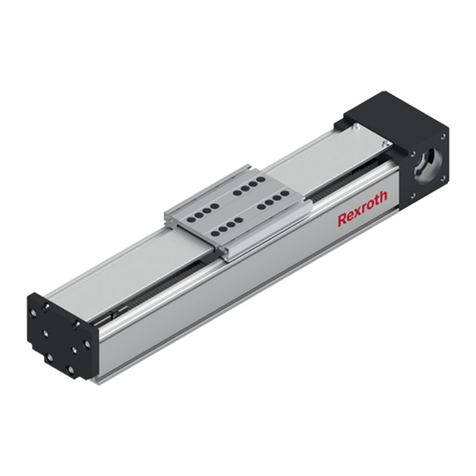
Bosch
Bosch Rexroth FMS User manual

Bosch
Bosch Rexroth IndraControl VAC 31 User manual

Bosch
Bosch CCU-Modul Operating manual
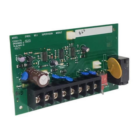
Bosch
Bosch D192G User manual

Bosch
Bosch CM744B How to use

Bosch
Bosch FLM-420/4-CON-S User manual
Popular Control Unit manuals by other brands

Festo
Festo Compact Performance CP-FB6-E Brief description

Elo TouchSystems
Elo TouchSystems DMS-SA19P-EXTME Quick installation guide

JS Automation
JS Automation MPC3034A user manual

JAUDT
JAUDT SW GII 6406 Series Translation of the original operating instructions

Spektrum
Spektrum Air Module System manual

BOC Edwards
BOC Edwards Q Series instruction manual

KHADAS
KHADAS BT Magic quick start

Etherma
Etherma eNEXHO-IL Assembly and operating instructions

PMFoundations
PMFoundations Attenuverter Assembly guide

GEA
GEA VARIVENT Operating instruction

Walther Systemtechnik
Walther Systemtechnik VMS-05 Assembly instructions

Altronix
Altronix LINQ8PD Installation and programming manual

