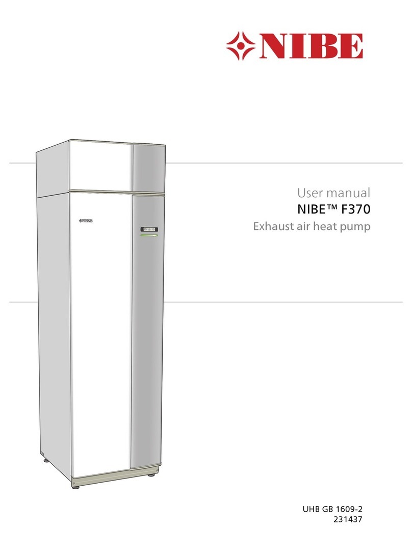
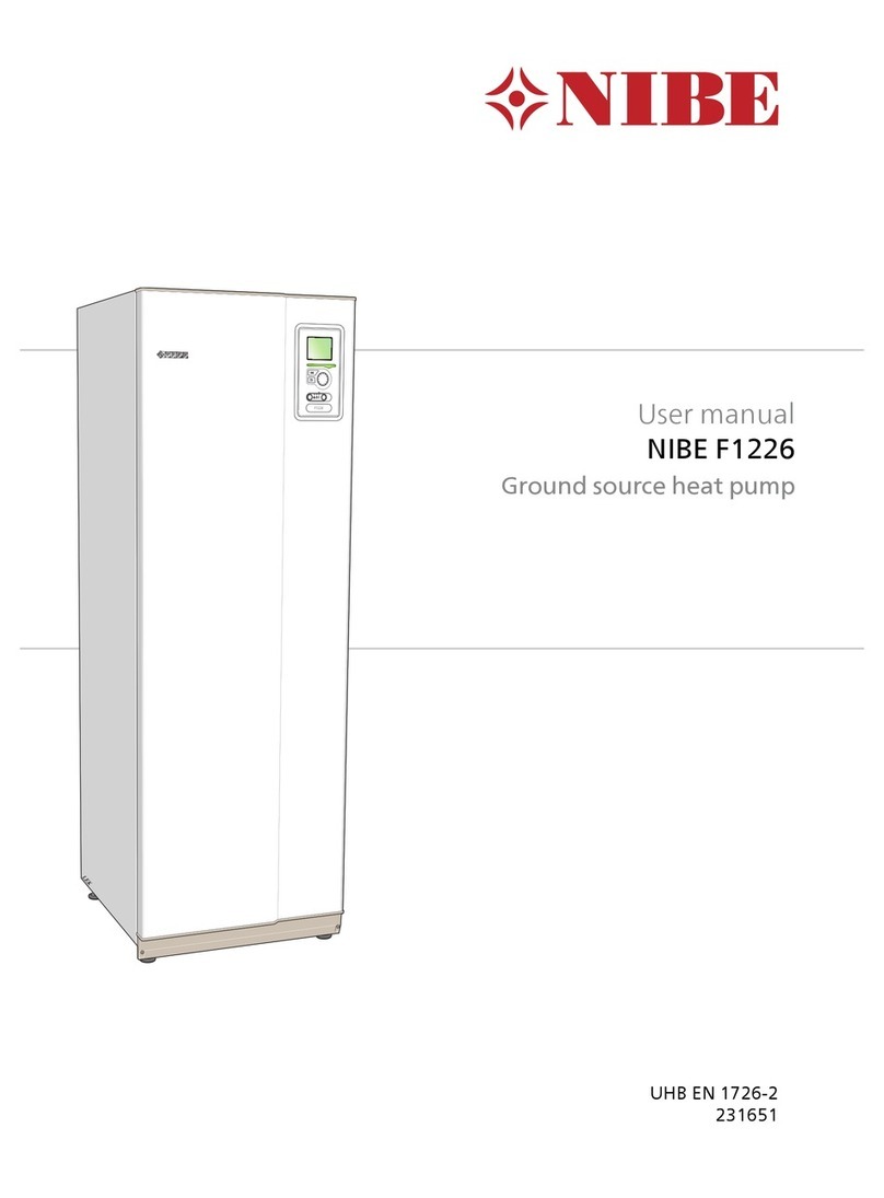
Nibe F1226 series Operating instructions

SE
SERVICEINSTRUKTION - Byte av beredare
NIBE F1226/F1245/F1255
GB
SERVICE INSTRUCTIONS - Replacing heater on
NIBE F1226/F1245/F1255
DE
SERVICEANLEITUNG - Speicherwechsel für
NIBE F1226/F1245/F1255
SIT SV 1927-4
431300
SERVICEINSTRUKTION
LEK


SERVICEINSTRUKTION
Allmänt
Vid byte av beredare i F1226/F1245/F1255 flyttas kylmo-
dul, rörkopplingar, isolering och all elektrisk utrustning
över från den befintliga värmepumpen till den nya bere-
daren med stativ.
OBS!
Eventuell service får bara utföras av en person
med kompetens för uppgiften.
Vid utbyte av komponenter på
F1226/F1245/F1255 får enbart reservdelar från
NIBE användas.
BIPACKADE KOMPONENTER
BeskrivningAntalArt.nr
Buntband till isoleringen för KB-venti-
lerna (QM33, QM34).
8 st016 940
Låsbleck till ventiler (QM31, 32, 33,
34).
4 st028 028
Packning avstängningsventil elpatron
(QM31).
1 st033 658
Stativfästen för ellådor.4 st037 312
Packningssats med 8 st O-ringar för
QM31, 32, 33, 34.
1 st059 392
Isolertejp 300x50x3, för isolering av
KB-ventilerna (QM32, 33).
1 st425 728
Vinkelkoppling för anslutning mot VV-
laddslinga.
2 st524 210
Adapter till elanod1 st818 159
Clips till givare BT6 och BT72 st036 982
3Kapitel 1 | Allmänt
Allmänt

Byte av beredare på
NIBE
F1226/F1245/F1255
OBS!
Elinstallation samt eventuell service ska göras
under överinseende av behörig elinstallatör.
Bryt strömmen med arbetsbrytaren innan
eventuell service. Elektrisk installation och
ledningsdragning ska utföras enligt gällande
bestämmelser.
FÖRBEREDELSER, ISÄRTAGNING
1. Gör värmepumpen spänningslös.
2. Ta bort frontluckan.
1
2
LEK
LEK
LEK
LEK
LEK
ALossa skruvarna i frontplåtens nederkant.
BLyft plåten utåt i nederkant och upp.
3. Ta bort kylmodulens servicelucka.
4. Töm varmvattenberedaren på vatten, töm klimat-
och köldbärarkretsarna genom (QM1) och (QM2).
TIPS!
Varmvattenberedaren töms genom hävert-
principen.
Detta kan ske dels genom säkerhetsventil
som monterats på inkommande kallvatten-
ledning eller genom att stoppa ner en slang
i kallvattenanslutningen.
OBS!
Varmt vatten kan förekomma vid tömning
av varmattenberedaren. Skållningsrisk kan
föreligga.
QM2
QM1
5. Koppla loss värmepumpen från installationen.
Kapitel 2 | Byte av beredare på NIBE F1226/F1245/F12554

6. Vid behov dra fram värmepumpen.
7. Ta bort sidoluckor, topplåt och ljudisoleringsskivor
placerade i stativramen mellan kylmodul och sidoluc-
kor.
LEK
LEK
LEK
ALossa skruvarna i över- och nederkant.
BVrid luckan något utåt.
CFör luckan utåt och bakåt.
DMontering sker i omvänd ordning.
1
2
LEK
LEK
LEK
LEK
LEK
LEK
VÄNSTER ELLÅDA OCH ELPATRON,
ÖVERFLYTTNING
1. Ta bort toppisoleringen ovanför beredaren och
framför elpatronen, både på den gamla och nya en-
heten.
LEK
2. Ta bort skyddslocket för ellådan och plastkåpan
mellan vänster och höger ellåda.
LEK
1.
2.
A
B
LEK
A
B
1.
2.
3.
4.
5Kapitel 2 | Byte av beredare på NIBE F1226/F1245/F1255

3. Lossa bandkabel från elpatronkortet.
4. Lossa kablagekontakt.
5. Lossa kablagekontakten (skruvmejsel).
6. Lossa jordkabeln som är fäst i stativramens vänstra
sida.
LEK
4.4?
4.3?
4.6?
3
4
5
6
7. Lossa/ta bort kontakten från givare (BT2).
8. Lossa/ta bort kontakten från växelventilen (QN10).
LEK
4.7?
7
8
9. Gäller endast emaljerade beredare:
Lossa/ta bort kabelanslutningar från anoden.
OBS!
Notera kablarnas placering. Om kablarna
ansluts på fel position vid återmontering
uteblir korrosionsskyddet.
10. Lossa muttern på VB-framledning till laddslingan på
beredaren mot luftventilen (QM22).
10
9
LEK
9
10
11. Ta bort rörklammern på VB-framledning mellan elpa-
tronen och kylmodulen (QM31) och sära på koppling-
en.
12. Lossa/ta bort ellådan från dess fästen.
LEK
Press
Press
A
B
Kapitel 2 | Byte av beredare på NIBE F1226/F1245/F12556

13. Montera två nya fästen (bipackade) för ellådan på
den nya enhetens vänstra stativram. Varje fäste
har två fästtappar som sticks in i ramen och sedan
vrids fästet för fastlåsning.
LEK
A
B
14. Montera Conexvinkeln (bipackad) på framledningen
till laddslingan på den nya enheten.
15. Flytta över hela paketet (elpatron och ellåda) till den
nya enheten. (Vinkla ut elpatronen och håll i ellådan.)
LEK
16. Fäst ellådan i snabbfästena, jordkablen i stativramen
och dra åt kopplingen till laddslingan.
LEK
17. Gäller endast emaljerad beredare:
Anslut kablarna till anoden. Det är viktigt att dessa
ansluts på rätt position, ansluts de fel uteblir korro-
sionskyddet.
17
LEK
17
För att ansluta elanoden krävs adaptern som bipac-
kas.
7Kapitel 2 | Byte av beredare på NIBE F1226/F1245/F1255

HÖGER ELLÅDA, ÖVERFLYTTNING
1. Ta bort skyddslocket för ellådan och lossa eventuellt
yttre inkopplingar på ingångskortet (AA3).
LEK
1.
2.
LEK
1.
A
B
2.
2. Ta bort kablagekontakt(er) från displayen.
3. Demontera displayen. Tryck in spärren upptill på
displayens baksida och lyft displayen något.
LEK
A
B
C
4. Dra ut givare (BT6, BT7) och frilägg dess kablage.
LEK
4.7?
4.??
BT7
BT6
5. Ta bort plåtfästet för displayen (två skruvar i stativra-
men).
6. Lossa ellådans jordkabel. (Fäst med en skruv i stativ-
ramen.)
LEK
Kapitel 2 | Byte av beredare på NIBE F1226/F1245/F12558

7. Lossa/ta bort kablagekontakter anslutna mot kylmo-
dulen.
8. Gäller endast modeller med energimätare:
Lossa kablagekontakten på energimätaren.
LEK
9. Montera två nya fästen (bipackade) för ellådan på
den nya enhetens högra stativram. Varje fäste har
två fästtappar som sticks in i ramen och sedan vrids
fästet för fastlåsning.
A
B
LEK
10. Lossa ellådan från dess snabbfästen.
LEK
Press
Press
A
A
B
11. Ta bort och flytta över ellådan med kabelgenomför-
ningsslang till den nya enheten.
LEK
9Kapitel 2 | Byte av beredare på NIBE F1226/F1245/F1255

12. Fäst ellådan i snabbfästena och jordkabeln i stativra-
men.
LEK
13. Montera plåtfästet för displayen (två skruvar) på den
nya enheten.
14. Montera displayen och anslut kablagekontakten(er)
mot displayen.
KYLMODUL OCH VÄRME/KÖLDBÄRARRÖR,
ÖVERFLYTTNING
1. Ta bort det övre låsblecket från avstängningsventi-
lerna (QM32, QM33, QM34) och sära på kopplingar-
na.
LEK
LEK
1
2. Ta bort köldbärarrören bakifrån och lägg dem åtsidan.
LEK
3. Lossa/ta bort de två skruvarna som håller kylmodu-
len.
LEK
3
4. Dra ut kylmodulen och flytta över den till nya enhe-
ten. Sätt dit skruvarna och dra åt dem.
5. Montera köldbärarrören med nya O-ringar (bipacka-
de) i den nya enheten. Stick in dem bakifrån och
anslut kopplingarna (QM33) och (QM34) med lås-
bleck. Sätt dit kopplingarnas isolering och spännfast
med bipackade buntband.
QM33
QM32QM34
Kapitel 2 | Byte av beredare på NIBE F1226/F1245/F125510

6. Lossa Conexmuttern på VB returröret från den nya
enhetens laddslinga. (Placerad i bakkant, upptill på
höger sida.)
LEK
6
7. Montera Conexvinklen (bipackad) på laddslingans
returledning på den nya enheten.
8. Flytta över VB-returrör till den nya enheten och dra
åt kopplingen på laddslingans returrör och anslut till
avstängningsventil (QM32) med låsbleck (kom ihåg
nya O-ringar).
LEK
9. Anslut kablagekontakter från kylmodulen mot elpa-
tronkort (AA1) och grundkort (AA2).
10. Placera givare (BT6, BT7) i dess clips enligt bild.
Montera givaren i dykröret och se till att benen på
clipset riktas mot beredaren. Det görs enklast genom
att hålla i fliken på clipset som pekas ut på bilden.
11Kapitel 2 | Byte av beredare på NIBE F1226/F1245/F1255

11. Anslut kablagekontakt på växelventilen (QN10) och
kontakt till givare (BT2). Se till att kablagen hamnar
korrekt i sina kabelkanaler.
LEK
4.4?
4.3?
4.7?
4.6?
BT2
QN10
12. Gäller endast modeller med energimätare:
Anslut kablagekontakten på energimätaren.
LEK
13. Anslut bandkabel (A) till elpatronkortet (AA1) och
anslut kablagekontakt (B) till elpatronkortet (AA1)
plint –X10.
LEK
4.4?
4.3?
A
B
PE
OBS!
Kontrollera jordanslutning och säkerställ
elektrisk anslutning mellan jordplint AA1-
X1 och stativ genom resistansmätning.
14. Sätt dit skyddslocken för ellådorna.
IHOPSÄTTNING, DRIFTSÄTTNING
1. Montera ljudisoleringsskivor i stativramens nedre
del och sidoplåtar.
2. Anslut värmepumpen mot köldbärar- och värmesy-
stem och anslut yttre elanslutningar.
3. Kontrollera eventuella läckage, att givarvärden verkar
rimliga och gör en funktionskontroll.
4. Montera toppisoleringen över beredaren och framför
beredaren, topplock och kylmodulens servicelucka.
5. Flytta över etiketter med serienummer/teknisk data
från den gamla till den nya enheten.
6. Montera frontluckan.
Kapitel 2 | Byte av beredare på NIBE F1226/F1245/F125512

SERVICE INSTRUCTIONS
General
When replacing the heater in F1226/F1245/F1255 the
cooling module, pipe connections, insulation and all
electrical equipment are transferred from the existing
heat pump to the heater with stand.
NOTE
Servicing should only be carried out by persons
with the necessary expertise.
When replacing components on
F1226/F1245/F1255 only replacement parts
from NIBE may be used.
SUPPLIED COMPONENTS
DescriptionQuant-
ity
Part No.
Cable tie for insulation for the Brine
valves (QM33, QM34).
8 x016 940
Securing plate for valves (QM31, 32,
33, 34).
4 x028 028
Gasket shut-off valve immersion
heater (QM31).
1 x033 658
Stand mountings for distribution
boxes.
4 x037 312
Gasket kit with 8 O-rings for QM31,
32, 33, 34.
1 x059 392
Insulation tape 300x50x3, for insula-
tion of Brine valves (QM32, 33).
1 x425 728
Angle connector for connection to
HW charge coil.
2 x524 210
Adapter for electrical anode1 x818 159
Clip for sensor BT6 and BT72 x036 982
13Kapitel 1 | General
General

Replacement of heater
on NIBE
F1226/F1245/F1255
NOTE
Electrical installation and service must be car-
ried out under the supervision of a qualified
electrician. Cut the current with the circuit
breaker before carrying out any servicing.
Electrical installation and wiring must be carried
out in accordance with the stipulations in force.
PREPARATIONS, DISMANTLING
1. Disconnect the power from the heat pump.
2. Remove the front cover
1
2
LEK
LEK
LEK
LEK
LEK
ARemove the screws from the lower edge of the
front panel.
BLift the panel out at the bottom edge and up.
3. Remove the cooling module's service cover.
4. Drain the water heater of water, empty the climate
and brine circuits through (QM1) and (QM2).
TIP
The siphon principle is used to empty the
hot water heater.
This can be done either via the safety valve
on the incoming cold water pipe or by in-
serting a hose into the cold water connec-
tion.
NOTE
There may be some hot water when
draining the water heater. There is a risk
of scalding.
QM2
QM1
5. Disconnect the heat pump from the installation.
Kapitel 2 | Replacement of heater on NIBE F1226/F1245/F125514

6. If necessary pull the heat pump forward.
7. Remove side covers, top panel and sound insulation
sheets in the stand frame between the cooling
module and side covers.
LEK
LEK
LEK
ARemove the screws from the upper and lower
edges.
BTwist the cover slightly outward.
CMove the hatch outwards and backwards.
DAssembly takes place in the reverse order.
1
2
LEK
LEK
LEK
LEK
LEK
LEK
LEFT DISTRIBUTION BOX AND IMMERSION
HEATER, TRANSFERRING
1. Remove the top insulation above the heater and in
front of the immersion heater, both on the old and
the new unit.
LEK
2. Remove the protective cover of the distribution box
and the plastic cover between the right and left
junction boxes.
LEK
1.
2.
A
B
LEK
A
B
1.
2.
3.
4.
15Kapitel 2 | Replacement of heater on NIBE F1226/F1245/F1255

3. Disconnect the ribbon cable from the immersion
heater board.
4. Disconnect wiring connector
5. Disconnect the wiring connector (screwdriver).
6. Disconnect the ground cable secured on the left
hand side of the stand frame.
LEK
4.4?
4.3?
4.6?
3
4
5
6
7. Disconnect/remove the connector from sensor
(BT2).
8. Disconnect/remove the connector from the reversing
valve (QN10).
LEK
4.7?
7
8
9. Only applies to enamelled heaters:
Disconnect/remove the cable connectors from the
anode.
NOTE
Note the positions of the cables. If the
cables are connected in the wrong position
the corrosion protection will be absent
when reinstalled.
10. Slacken off the nut on the HM supply line to the
charge coil on the water heater to the air valve
(QM22).
10
9
LEK
9
10
11. Remove the pipe clamp on the HM supply line
between the immersion heater and the cooling
module (QM31) and separate the connector.
12. Disconnect/remove the distribution box from its
mounting.
LEK
Press
Press
A
B
Kapitel 2 | Replacement of heater on NIBE F1226/F1245/F125516

13. Install two new mountings (enclosed) for the distri-
bution box on the new unit's left stand frame. Each
mounting has two mounting pins that are inserted
in the frame and then twisted to secure it.
LEK
A
B
14. Install the Conex angle (supplied) on the supply line
to the charge coil on the new unit.
15. Transfer the whole package (immersion heater and
distribution box) to the new unit. (Angle out the im-
mersion heater and hold the distribution box.)
LEK
16. Secure the distribution box in the quick mountings,
the ground cable in the stand frame and tighten the
connection to the charge coil.
LEK
17. Only applies to enamelled heaters:
Connect the cables to the anode. It is important that
these are connected in the correct positions, if incor-
rectly connected the corrosion protection is absent.
17
LEK
17
To connect the electrical anode, the enclosed ad-
apter is required.
17Kapitel 2 | Replacement of heater on NIBE F1226/F1245/F1255

RIGHT DISTRIBUTION BOX, TRANSFERRING
1. Remove the protective cover of the distribution box
and disconnect any external connections to the input
board (AA3).
LEK
1.
2.
LEK
1.
A
B
2.
2. Remove wiring connector(s) from the display.
3. Remove the display. Press the top catch on the re-
verse side of the display and lift the display slightly.
LEK
A
B
C
4. Pull out sensor (BT6, BT7) and release its wiring.
LEK
4.7?
4.??
BT7
BT6
5. Remove the panel mounting for the display (two
screws in the stand frame).
6. Disconnect the distribution box's ground cable.
(Secured with a screw in the stand frame.)
LEK
Kapitel 2 | Replacement of heater on NIBE F1226/F1245/F125518

7. Disconnect/remove the wiring connectors connected
to the cooling module.
8. Only applies to models with energy meters:
Disconnect the wiring connector on the energy
meter.
LEK
9. Install two new mountings (enclosed) for the distri-
bution box on the new unit's right stand frame. Each
mounting has two mounting pins that are inserted
in the frame and then twisted to secure it.
A
B
LEK
10. Disconnect the distribution box from its quick re-
lease mountings.
LEK
Press
Press
A
A
B
11. Remove and transfer the distribution box with cable
grommet hose to the new unit.
LEK
19Kapitel 2 | Replacement of heater on NIBE F1226/F1245/F1255

12. Secure the distribution box in the quick release
mountings and the ground cable in the stand frame.
LEK
13. Install the panel mounting for the display (two
screws) on the new unit.
14. Install the display and connect the wiring connect-
or(s) to the display.
COOLING MODULE AND HEATING/BRINE
PIPES, TRANSFERRING
1. Remove the upper securing plate from the shut off
valves (QM32, QM33, QM34) and separate the
connections.
LEK
LEK
1
2. Remove the brine pipes from behind and put them
aside.
LEK
3. Loosen/remove the two screws holding the cooling
module.
LEK
3
4. Pull out the cooling module and transfer it to the
new unit. Install the screws and tighten them.
5. Install the brine pipes with new O rings (enclosed)
on the new unit. Insert them from behind and con-
nect connections (QM33) and (QM34) with securing
plate. Install the insulation for the connectors and
secure using the cable ties enclosed.
QM33
QM32QM34
Kapitel 2 | Replacement of heater on NIBE F1226/F1245/F125520
Other manuals for F1226 series
4
This manual suits for next models
2
Table of contents
Languages:
Other Nibe Heat Pump manuals
Popular Heat Pump manuals by other brands

Dimplex
Dimplex SIH 9TE Installation and operating instructions

Kospel
Kospel HPMI2 - 8 Installation and operating instructions

Bryant
Bryant 607E Series installation instructions

Fujitsu
Fujitsu Waterstage Comfort 5 Operation manual

Daikin
Daikin RKS71FV1B Service manual

Viessmann
Viessmann VITOCAL 300-G Installation and service instructions