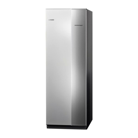
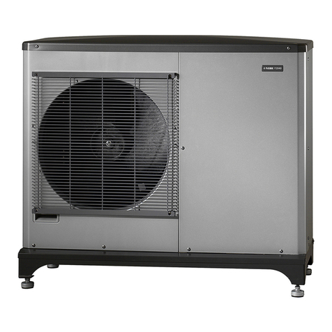
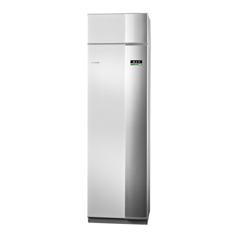
Nibe F1226 series User manual

User manual
LEK
NIBE F1226
Ground source heat pump
UHB EN 1726-2
231651

Quick guide
Navigation
Ok button (confirm/select)
Back button (back/undo/exit)
Control knob (move/increase/reduce)
A detailed explanation of the button functions can be found on page
10.
How to scroll through menus and make different settings is described
on page 14.
Set the indoor climate
2X
INDOOR CLIMATE
HEAT PUMP
INFO
HOT WATER
temperature1.1.1
The mode for setting the indoor temperature is accessed by pressing
the OK button twice, when in the start mode in the main menu. Read
more about the settings on page 22.
Increase hot water volume
2X
1X
INDOOR CLIMATE
HEAT PUMP
INFO
HOT WATER
off
temporary lux2.1
3 hrs
6 hrs
12 hrs
one time increase
To temporarily increase the amount of hot water, first turn the control
knob to mark menu 2 (water droplet) and then press the OK button
twice. Read more about the settings on page 31.
In event of disturbances in comfort
If you experience a disturbance in comfort of any kind, there are some
measures you can take yourself before you need to contact your installer.
See page 44 for instructions.

Table of Contents
41 Important information
4Installation data
5Safety information
6Serial number
7F1226 – An excellent choice
82 The heat pump – the heart of the house
9Heat pump function
10Contact with F1226
18Maintenance of F1226
223 F1226 – at your service
22Set the indoor climate
31Set the hot water capacity
34Get information
37Adjust the heat pump
434 Disturbances in comfort
43Manage alarm
44Troubleshooting
46Only additional heat
475 Technical data
486 Glossary
54Item register
55Contact information
3NIBE F1226Table of Contents |

1 Important information
Installation data
F1226Product
Serial number
Installation date
Installer
Type of brine -
Mixing ratio/freezing point
Active drilling depth/collector
length
Accessories
✔
SetFact-
ory
set-
tings
NameNo.
0heating curve (offset)1.9.1.1
7heating curve (curve slope)1.9.1.1
Serial number must always be given
Certification that the installation is carried out according to instructions
in the accompanying installer manual and applicable regulations.
_________________________Signed__________________Date
NIBE F1226Chapter 1 | Important information4

Safety information
This appliance can be used by children aged from 8
years and above and persons with reduced physical,
sensory or mental capabilities or lack of experience
and knowledge if they have been given supervision or
instruction concerning use of the appliance in a safe
way and understand the hazards involved. Children
shall not play with the appliance. Cleaning and user
maintenance shall not be made by children without
supervision.
Rights to make any design or technical modifications
are reserved.
©NIBE 2017.
NOTE
Do not start the heat pump, if there is a risk that the water in the
system has frozen.
NOTE
If the supply cable is damaged, only NIBE, its service
representative or similar authorised person may re-
place it to prevent any danger and damage.
5NIBE F1226Chapter 1 | Important information

Symbols
NOTE
This symbol indicates danger to person or machine .
Caution
This symbol indicates important information about what you should
observe when maintaining your installation.
TIP
This symbol indicates tips on how to facilitate using the product.
Marking
The CE mark is obligatory for most products sold in the EU, regardless
of where they are made.
CE
Classification of enclosure of electro-technical equipment.IP21
Danger to person or machine.
!
Serial number
The serial number can be found at the bottom right of the front cover and
in the info menu (menu 3.1).
Serial number
Caution
You need the product's (14 digit) serial number for servicing and support.
NIBE F1226Chapter 1 | Important information6

F1226 – An excellent choice
F1226 is part of a new generation of heat pumps, which have been intro-
duced to supply your home with inexpensive and environmentally friendly
heating. Heat production is safe and economical with integrated hot water
heater, immersion heater, circulation pump and control system.
The heat pump can be connected to an optional low temperature heat
distribution system. e.g. radiators, convectors or under floor heating. It is
also prepared for connection to several different products and accessories,
e.g. extra water heater and ventilation recovery.
An immersion heater of 7 kW can be connected automatically if anything
unforeseen should occur or as back-up operation (factory setting 6 kW).
F1226 is equipped with a control computer for good comfort, good eco-
nomy and safe operation. Clear information about status, operation time
and all temperatures in the heat pump are shown on the large and easy
to read display. This means, for example, that external unit thermometers
are not necessary.
Excellent properties for F1226:
■Integrated water heater
There is a water heater integrated in the heat pump, which is insulated
with environmentally friendly cellular plastic for minimal heat loss.
■Display with user instructions
The heat pump has a large display with easy-to-understand menus that
facilitate setting a comfortable climate.
■Simple troubleshooting
In the event of a fault, the heat pump display shows what happened
and the actions to be taken.
7NIBE F1226Chapter 1 | Important information

2 The heat pump – the heart of
the house
Värmebärare
Köldmedium
Köldbärare
Värmekälla
Förångare
Kondensor 100 °C
0 °C-3 °C
-2 °C
50 °C40 °C
Expansionsventil Kompressor
A
D
F
H
B
C
E
G
Heating medium
Värmebärare
Köldmedium
Köldbärare
Värmekälla
Förångare
Kondensor 100 °C
0 °C-3 °C
-2 °C
50 °C40 °C
Expansionsventil Kompressor
A
D
F
H
B
C
E
G
Brine
Refrigerant
Evaporator
Condenser
Expansion valve Compressor
Heat source
1
2
3
The temperatures are only examples and may vary between different installations and
time of year.
NIBE F1226Chapter 2 | The heat pump – the heart of the house8

Heat pump function
A heat pump can use stored solar energy from rock, ground or water in
order to heat a property. The conversion of stored energy in nature to
property heating occurs in three different circuits. In the brine circuit, (1)
, free heat energy is retrieved from the surroundings and transported to
the heat pump. In the refrigerant circuit, (2) , the heat pump increases the
retrieved heat's low temperature to a high temperature. In the heating
medium circuit, (3) , the heat is distributed around the house.
The temperatures below are only examples and may vary between different
installations and times of year.
Brine circuit
In a hose, collector, an anti-freeze liquid, brine, circulates from the heat
pump out to the heat source (rock/ground/lake). The energy from the
heat source is stored by it heating the brine a few degrees, from about
–3°C to about 0 °C.
A
The collector then routes the brine to the heat pump’s evaporator. Here,
the brine releases heat energy and the temperature drops a few degrees.
The liquid then returns to the heat source to retrieve energy again.
B
Refrigerant circuit
Another liquid circulates in a closed system in the heat pump, a refrigerant,
which also passes the evaporator. The refrigerant has a very low boiling
point. In the evaporator the refrigerant receives the heat energy from the
brine and starts to boil.
C
The gas that is produced during boiling is routed into an electrically
powered compressor. When the gas is compressed, the pressure increases
and the gas's temperature increases considerably, from approx. 5ーC to
approx. 100 ーC.
D
From the compressor, gas is forced into a heat exchanger, condenser,
where it releases heat energy to the heating system in the house,
whereupon the gas is cooled and condenses to a liquid form again.
E
As the pressure is still high, the refrigerant can pass an expansion valve,
where the pressure drops so that the refrigerant returns to its original
temperature. The refrigerant has now completed a full cycle. It is routed
to the evaporator again and the process is repeated.
F
Heat medium circuit
The heating energy that the refrigerant releases in the condenser is re-
trieved by the heat pump's boiler section.
G
The heating medium circulates in a closed system and transports the heated
water's heat energy to the house water heater and radiators/heating coils.
H
9NIBE F1226Chapter 2 | The heat pump – the heart of the house
Contact with F1226
Display unit
A
B
C
D
E
F
Display
Status lamp
OK button
Back button
Control knob
Switch
INDOOR CLIMATE
HEAT PUMP
INFO
HOT WATER
F1226 GUSB port
There is a display unit on the front of the heat pump, which is used to
communicate with F1226.. Here you:
■switch on, switch off or set the heat pump in emergency mode.
■sets the indoor climate and hot water as well as adjusts the heat pump
to your needs.
■receive information about settings, status and events.
■see different types of alarms and receive instructions about how they
are to be rectified.
Display
Instructions, settings and operational information are shown on the
display. You can easily navigate between the different menus and
options to set the comfort or obtain the information you require.
A
NIBE F1226Chapter 2 | The heat pump – the heart of the house10

Status lamp
The status lamp indicates the status of the heat pump. It:
■lights green during normal operation.
■lights yellow in emergency mode.
■lights red in the event of a deployed alarm.
B
OK button
The OK button is used to:
■confirm selections of sub menus/options/set values/page in the
start guide.
C
Back button
The back button is used to:
■go back to the previous menu.
■change a setting that has not been confirmed.
D
Control knob
The control knob can be turned to the right or left. You can:
■scroll in menus and between options.
■increase and decrease the values.
■change page in multiple page instructions (for example help text
and service info).
E
Switch
The switch assumes three positions:
■On ()
■Standby ( )
■Emergency mode ( )
Emergency mode must only be used in the event of a fault on the
heat pump. In this mode, the compressor switches off and the im-
mersion heater engages. The heat pump display is not illuminated
and the status lamp illuminates yellow.
F
11NIBE F1226Chapter 2 | The heat pump – the heart of the house
USB port
The USB port is hidden beneath the plastic badge with the product
name on it.
The USB port is used to update the software.
Visit www.nibeuplink.com and click the "Software" tab to download
the latest software for your installation.
G
NIBE F1226Chapter 2 | The heat pump – the heart of the house12

Menu system
INDOOR CLIMATE
HEAT PUMP
INFO
HOT WATER
Indoor temperature -
(if room sensors are
installed)
Hot water temp.
Temporary lux (if
activated)
Outdoor
temperature
Estimated amount of
hot water
INDOOR CLIMATE
Setting the indoor climate. See page 22.
Menu 1
HOT WATER
Setting the hot water production. See page 31.
Menu 2
INFO
Display of temperature and other operating information and access to
the alarm log. See page 34.
Menu 3
HEAT PUMP
Setting time, date, language, display, operating mode etc. See page 37.
Menu 4
13NIBE F1226Chapter 2 | The heat pump – the heart of the house
INDOOR CLIMATE
HEAT PUMP
INFO
HOT WATER
INDOOR CLIMATE 1
temperature
advanced
Marked main
menu
Menu number – marked sub menu Name and menu number – main menu
Symbol –
main menu
Status information – sub
menus
Name – sub menusSymbols – sub menus
Operation
To move the cursor, turn the control knob to the left or the
right. The marked position is brighter and/or has a light frame.
Selecting menu
To advance in the menu system select a main menu by marking
it and then pressing the OK button. A new window then opens with sub
menus.
Select one of the sub menus by marking it and then pressing the OK button.
NIBE F1226Chapter 2 | The heat pump – the heart of the house14

Selecting options
economy
comfort mode 2.2
normal
luxury
Alternative
In an options menu the current selected option is indicated by a green
tick.
To select another option:
1. Mark the applicable option. One of the options is pre-selected
(white).
2. Press the OK button to confirm the selected option. The selected
option has a green tick.
15NIBE F1226Chapter 2 | The heat pump – the heart of the house

Setting a value
time & date4.4
time
day
year
month
24 h
12 h
date
Values to be changed
To set a value:
1. Mark the value you want to set using the control knob.
2. Press the OK button. The background of the value becomes
green, which means that you have accessed the setting mode.
3. Turn the control knob to the right to increase the value and to
the left to reduce the value.
4. Press the OK button to confirm the value you have set. To change
and return to the original value, press the Back button.
Scroll through the windows
A menu can consist of several windows. Turn the control knob to scroll
between the windows.
Current menu
window
Number of windows
in the menu
Scroll through the windows in the start guide
language4.6
If the start guide is left on this page it closes
automatically in
60 min
start guide NIBE F1226
Arrows to scroll through window in start guide
1. Turn the control knob until one of the arrows in the top left corner (at
the page number) has been marked.
2. Press the OK button to skip between the steps in the start guide.
NIBE F1226Chapter 2 | The heat pump – the heart of the house16

Help menu
In many menus there is a symbol that indicates that extra help is
available.
To access the help text:
1. Use the control knob to select the help symbol.
2. Press the OK button.
The help text often consists of several windows that you can scroll between
using the control knob.
17NIBE F1226Chapter 2 | The heat pump – the heart of the house

Maintenance of F1226
Regular checks
Your heat pump is, in principle, maintenance free and therefore requires
minimal care after commissioning. On the other hand, it is recommended
that you check your installation regularly.
If something unusual occurs, messages about the malfunction appear in
the display in the form of different alarm texts. See alarm management
on page 43.
Level vessel
The brine that obtains the heat in the ground is not normally
consumed but just pumped around. In most installations, there
is a level vessel where you can check if there is sufficient fluid
in the system. Ask your installer if you are unsure where the
level vessel is located. The level can vary due to the fluid’s
temperature. If the level is below 1/3 topping up is required.
Contact your installer for assistance with filling.
2/3
LEK
1/3
LEK
1/3
LEK
2/3
LEK
Gamla bilder, med säkerhetsventil på nivåkärlet
Expansion vessel
The brine that obtains the heat in the ground is not normally
consumed but just pumped around. In some installations there
is an expansion tank instead of a level vessel (for example,
where the heat pump is not at the highest point in the brine
system) where the system pressure can be checked. Ask your
installer if you are unsure where the expansion tank is located.
The pressure can vary due to the fluid’s temperature. The
pressure should not fall below 0.5 bar. Contact your installer
for assistance with filling.
LEK
Safety valve
The water heater's safety valve sometimes releases a little water after hot
water usage. This is because the cold water, which enters the water heater
to replace the hot water, expands when heated causing the pressure to
rise and the safety valve to open.
NIBE F1226Chapter 2 | The heat pump – the heart of the house18

The function of the safety valve must be checked regularly. You can find
the safety valve on the incoming pipe (cold water) to the water heater.
Perform checks as follows:
1. Open the valve by turning the knob anti-clockwise carefully.
2. Check that water flows through the valve.
3. Close the valve by releasing it. If it does not close automatically when
released, turn it anti-clockwise slightly.
Saving tips
Your heat pump installation produces heat and hot water. This occurs via
the control settings you made.
Factors that affect the energy consumption are, for example, indoor tem-
perature, hot water consumption, the insulation level of the house and
whether the house has many large window surfaces. The position of the
house, e.g. wind exposure is also an affecting factor.
Also remember:
■Open the thermostat valves completely (except in the rooms that are to
be kept cooler for various reasons, e.g. bedrooms). The thermostats slow
the flow in the heating system, which the heat pump wants to com-
pensate with increased temperatures. It then works harder and consumes
more electrical energy.
■If you activate "Hot water Economy", less energy is used.
Power consumption
Energiförbrukning fördelat över året
0%
5%
10%
15%
20%
jan feb mars april maj juni juli aug sep okt nov dec
Månad
% av årsförbrukningen
The ground source heat pump's energy distribution is spread across
the year.
Month
Jan Feb Mar April May June July Aug Sep Oct Nov Dec
% of annual
consumption
Increasing the indoor temperature one degree increases the energy con-
sumption by approx. 5%.
19NIBE F1226Chapter 2 | The heat pump – the heart of the house

Domestic electricity
In the past it has been calculated that an average Swedish household has
an approximate annual consumption of 5000 kWh domestic electri-
city/year. In today's society it is usually between 6000-12000 kWh/year.
Approx.
annual
con-
sump-
tion
(kWh)
Normal Output
(W)
Equipment
StandbyOpera-
tion
3802200TV (Operation: 5 h/day, Standby: 19 h/day)
901011Digital box (Operation: 5 h/day, Standby:
19 h/day)
45515DVD (Operation: 2 h/week)
672160TV games console (Operation: 6 h/week)
50140Radio/stereo (Operation: 3 h/day)
1202100Computer incl. screen (Operation: 3 h/day,
standby 21 h/day)
175-60Bulb (Operation 8 h/day)
58-20Spot light, Halogen (Operation 8 h/day)
165-100Cooling (Operation: 24 h/day)
380-120Freezer (Operation: 24 h/day)
365-1500Stove, hob (Operation: 40 min/day)
310-3000Stove, oven (Operation: 2 h/week)
730-2000Dishwasher, cold water connection (Opera-
tion 1 time/day)
730-2000Washing machine (Operation: 1 times/day)
730-2000Tumble drier (Operation: 1 times/day)
100-1000Vacuum cleaner (Operation: 2 h/week)
50-400Engine block heater (Operation: 1 h/day, 4
months a year)
100-800Passenger compartment heater (Operation:
1 h/day, 4 months a year)
These values are approximate example values.
NIBE F1226Chapter 2 | The heat pump – the heart of the house20
Other manuals for F1226 series
4
Table of contents
Other Nibe Heat Pump manuals
Popular Heat Pump manuals by other brands

Multiaqua
Multiaqua MACH-060-1 Guide specifications

mundoclima
mundoclima MUCS-W9 Installation and owner's manual and information requirements

alphainnoTec
alphainnoTec WWB 20 operating manual

alphainnoTec
alphainnoTec SWC H1 Series operating manual

System air
System air SYSHP MINI SPLIT Installation and owner's manual

ACPro
ACPro Q6SE Series user manual

Envision
Envision NSKW 06 installation manual

HydroPro
HydroPro 7018522 User and service manual

Waterco
Waterco Electroheat ECO V 25KW user manual

alphainnoTec
alphainnoTec LW 71A operating manual

alphainnoTec
alphainnoTec SWC - Series operating manual

Magic-Pak
Magic-Pak MHP4 Series Installation and maintenance instructions